Final Project
Idea
In these months I have thought over my final project and decided to abandon my initial idea. I thought of a game for children to make a very simple (but equally boring) physiotherapy exercise: the simple, but fair, distribution of weight on the foot. Many people distribute it badly and hardly aware of it, especially children. They also often don't even like to do rehabilitation exercises. So I decided to model a foot on OnShape taking care to create the space in which to insert a strip of neopixel with three rgb leds (one that will be in the front part of the foot, one in the middle and one in the back).
Onshape
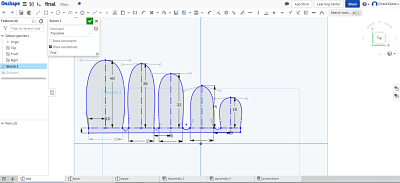
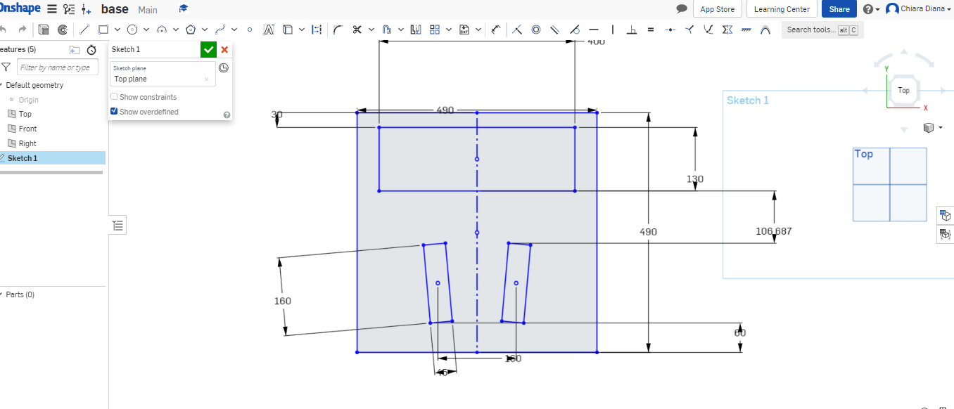
The technique I used to model my foot is this: I started from the fingers by simply drawing a fictitious straight line using the "construction" and "line" tools, then I created a curved line from this line using the "spline" tool and drew another fictitious line so I could use the "mirror" tool. I did so for all the fingers leaving a small space and a small curved "junction" between them. I then created a very small rectangle so as to have a straight line to connect the other part of the foot. Finally I extruded the part.
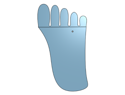
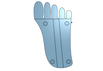
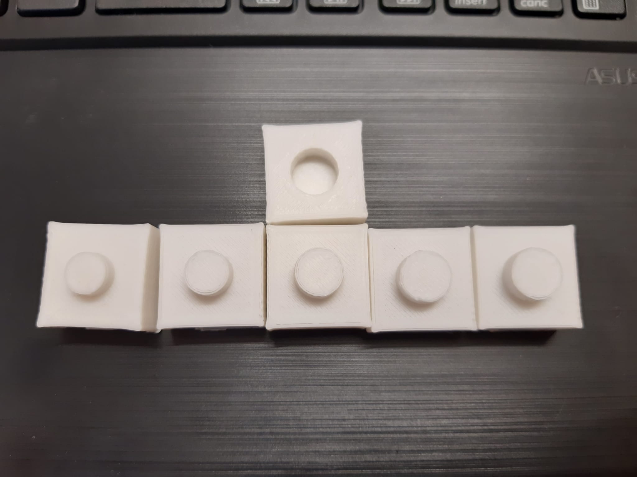
Then I created the sole of the foot in two parts and using the spline tool. Inside I will have to place the strip of neopixel so it was necessary to create the necessary pocket to insert it and create some keys to join them (obviously for one part subtractively extruded and for the other one additionally). So I extruded the two surfaces of 4 mm each and the keys of 2 mm. The pocket for the neopixels is 4 mm (even two millimeters less would have been enough but I preferred to be sure). As for the keys, instead, I did some tests: the radius of the circle is 10 mm for the female, but if I had left the same size for the male it would not have gone well. After some tests, I discovered that the radius of the male, to create a perfect fit would have to be 9.4 mm.
Before exporting the files to upload them to Meshmixer and analyze them and to Cura to prepare them for printing by setting the various sieves, I made an assembly and verified that the parts fit together without any problems and then I eliminated the fastened that joined the negative to the positive part and exported the two files separately.
Ultimaker Cura
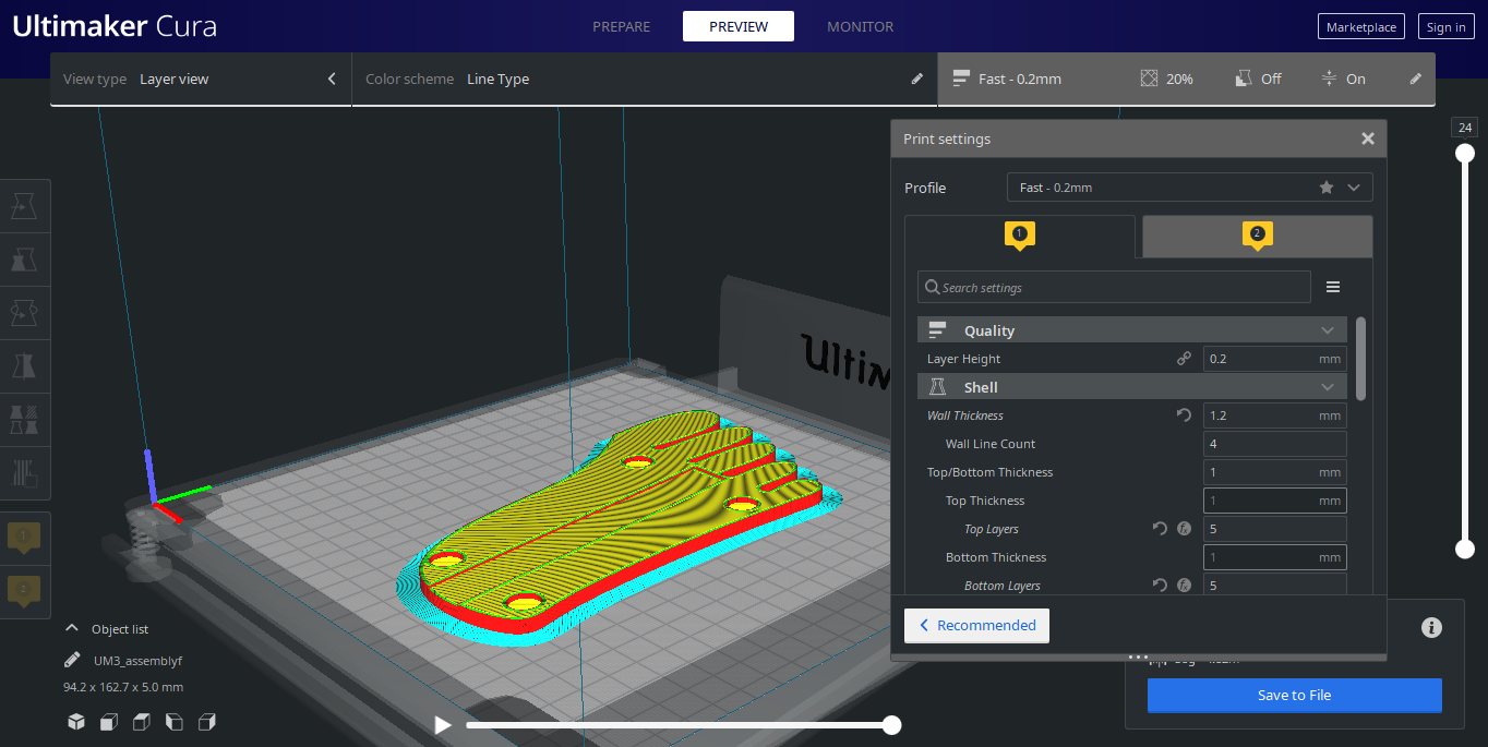
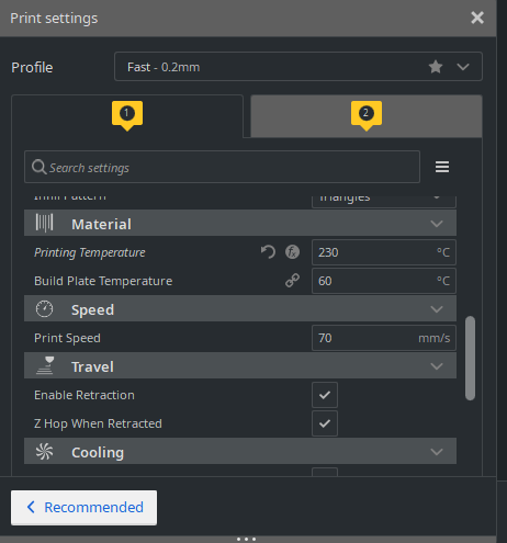
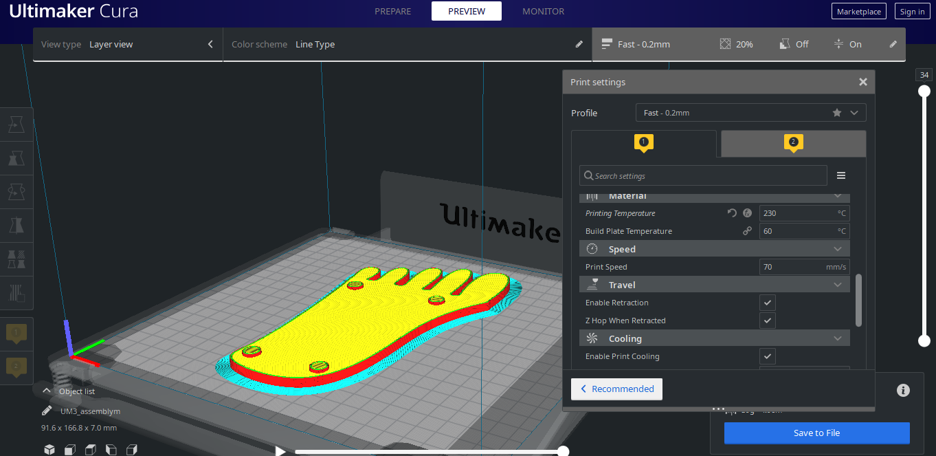
After I did the analysis on MeshMixer I imported the files on Cura to prepare the print files. You can see the selected sieves in the corousel below.
I thought a translucent PLA was necessary, but from the tests I realized it wasn't necessary. In fact, you can see the LED light from the white PLA very well.
Electronics
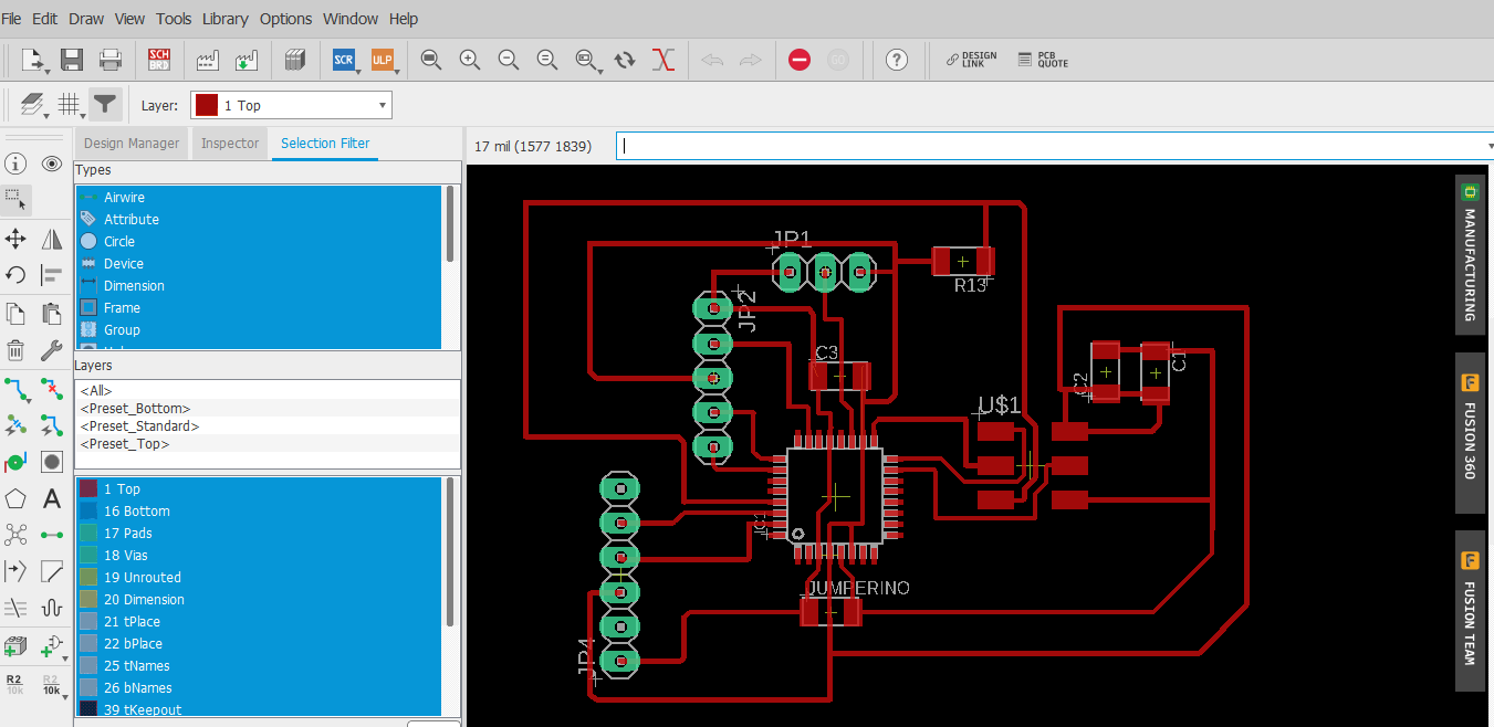
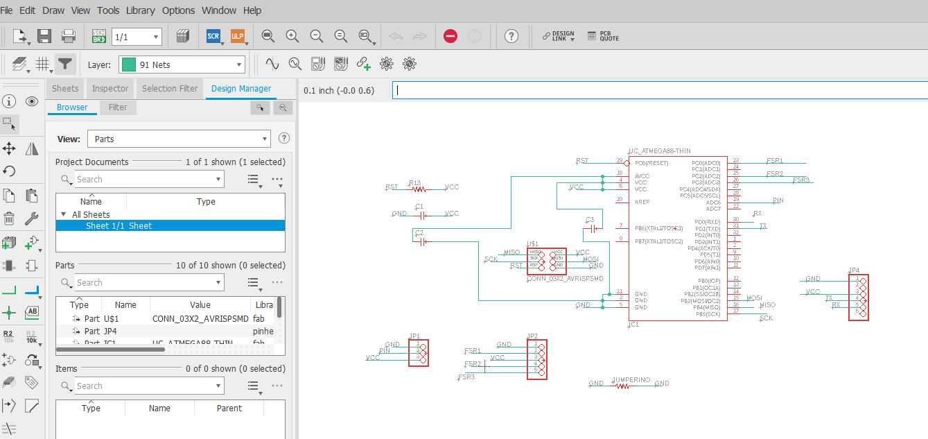
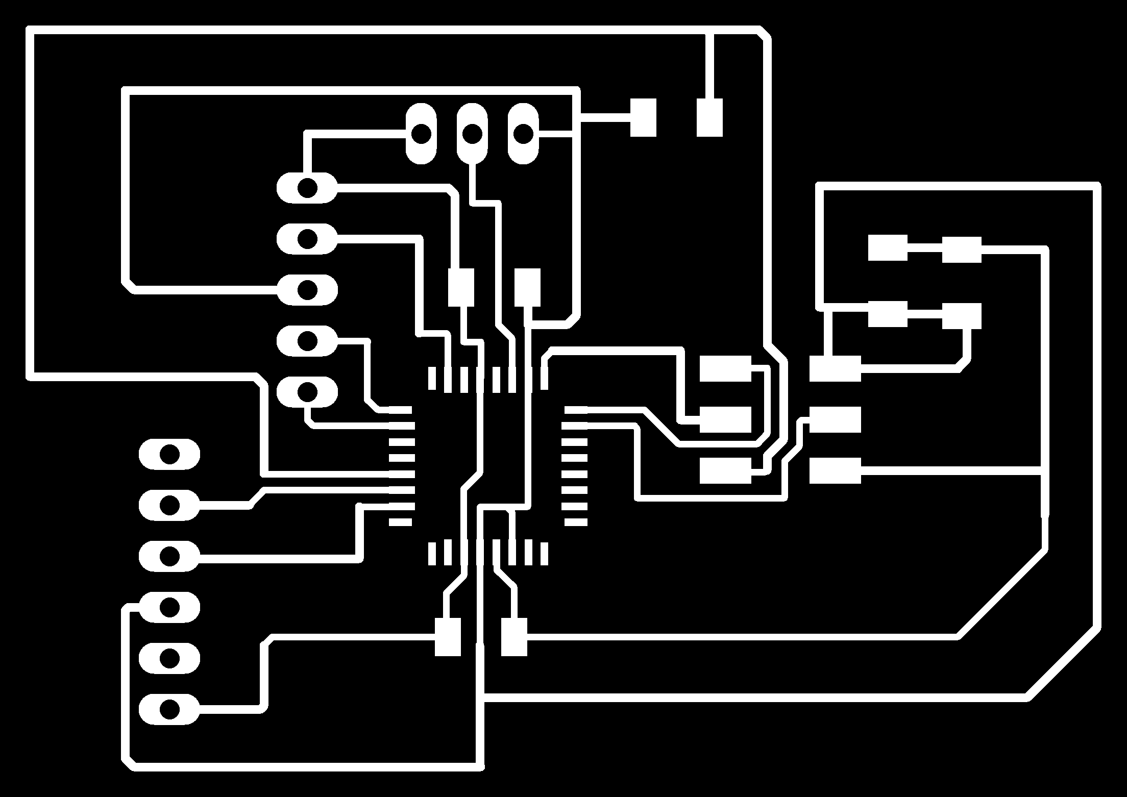
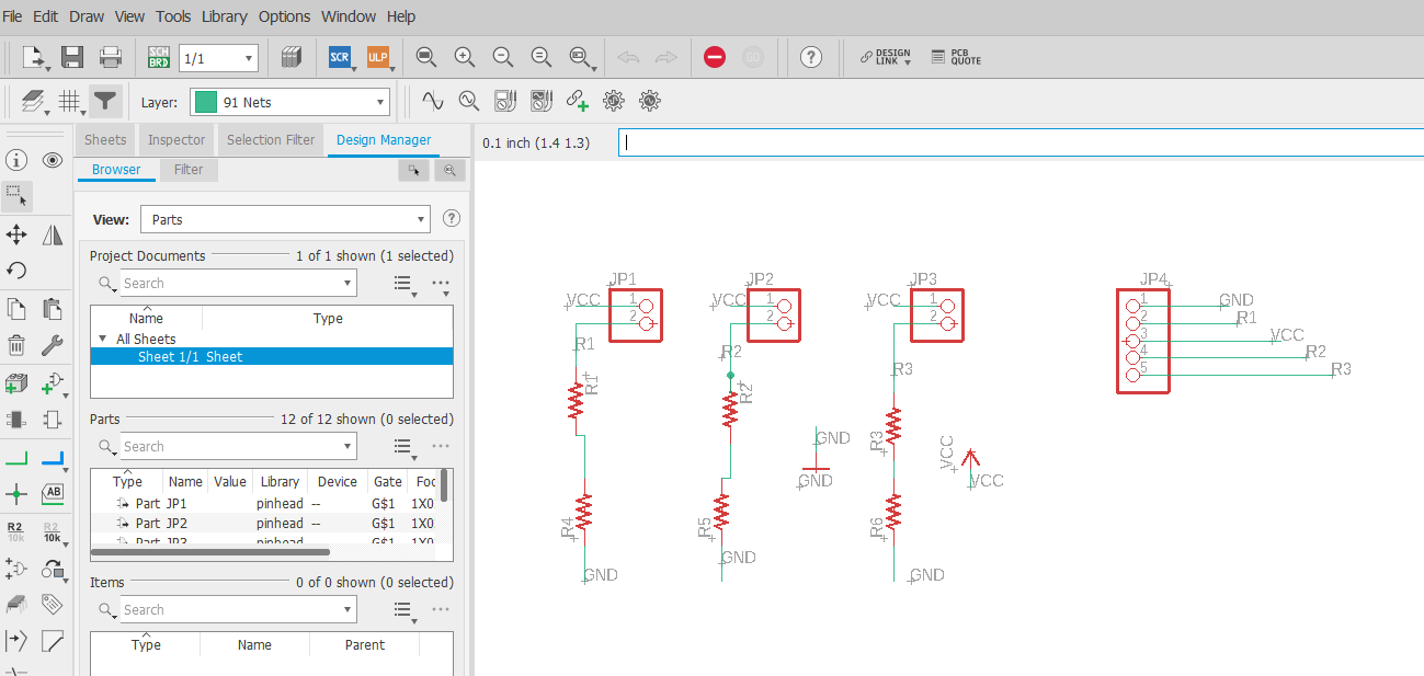
As for the electronics part I decided to build two different boards: one where I inserted the microcontroller, the isp and the ftdi, the pull up resistor and a capacitor for each ground and vcc and the header pins to create the connection with the neopixel strip and the board where I inserted the header pins for the fsr sensors. I had never used the atmega 328 before, so it was really helpful to consult both the datasheet and the Atmega 8/48/88/168/328 pinout
Here you can find all the material regarding the final board

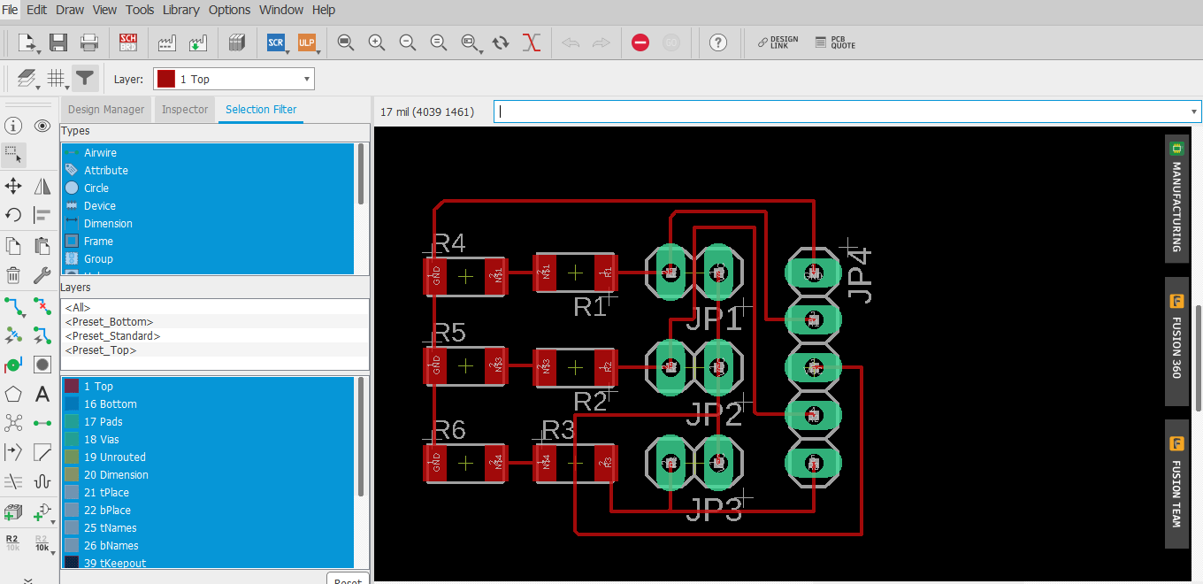
Here you can find all the material regarding the fsr board
Plywood boxes
In order to hide and protect the boards and to position the foot (Initially I had got the measurements wrong) I created 3 plywood boxes.
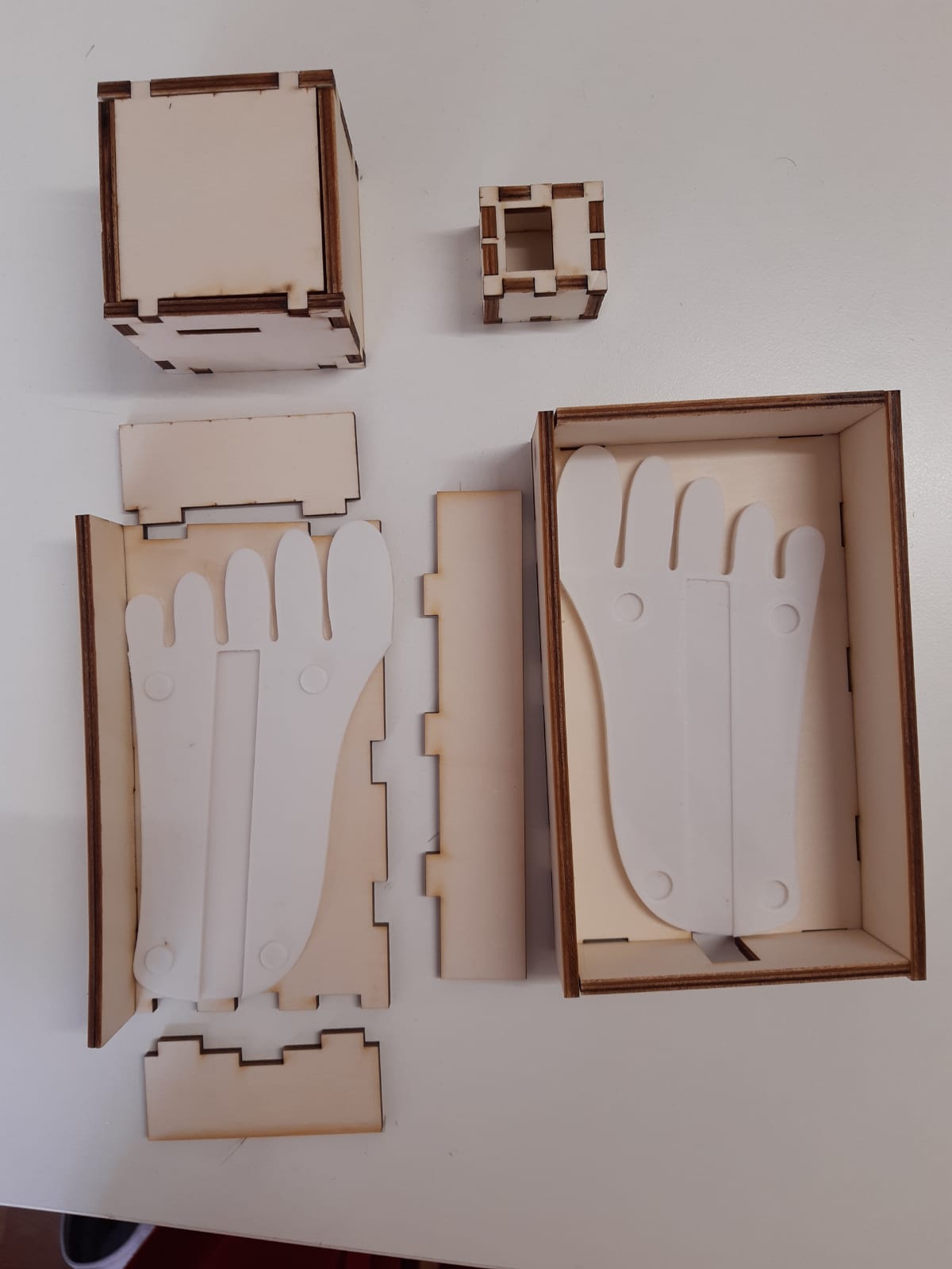
Box for the main board
Box for the FSR board
Box for the foot
Arduino Code
I set as input sensors the FSR and as output sensors the rgb leds contained in the neopixel strip. Each FSR is connected to a led. The weight is calculated in percentage: if it exceeds 80% then the led becomes red, if I set as input sensors the FSR and as output sensors the rgb leds contained in the neopixel strip. Each FSR is connected to a led. The weight is calculated in percentage: if it exceeds 80% then the led becomes red, if it is higher than 45% and lower than 80%, then the led becomes orange, if it is higher than 23% and lower than 44%, then the led becomes green, if higher than 0% and lower than 22%, then the led becomes blue, if there is no weight, then the led becomes white.
This is the Arduino codeProcessing Code
On Processing instead I wrote a code to have two different sound feedback: until the child can make the green LEDs light up (distributing the weight equally) he will hear (every 10 seconds) the sentence "Don't give up, you can do it". When he reaches the goal he will hear the phrase "Congratulations, you did it!". I particularly wanted to include this part because I think it's very important to encourage children not to give up and reward them when they can do something that is difficult for them.
This is the Processing Code
OnShape
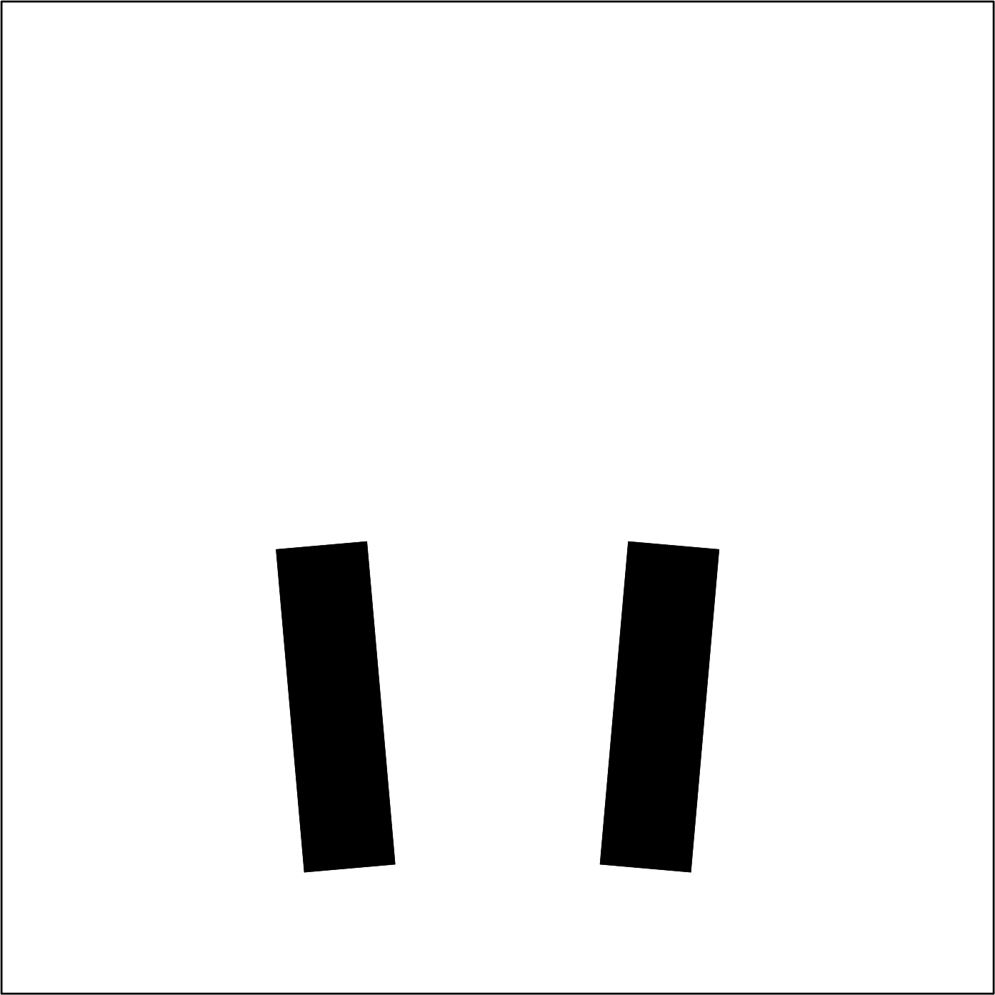
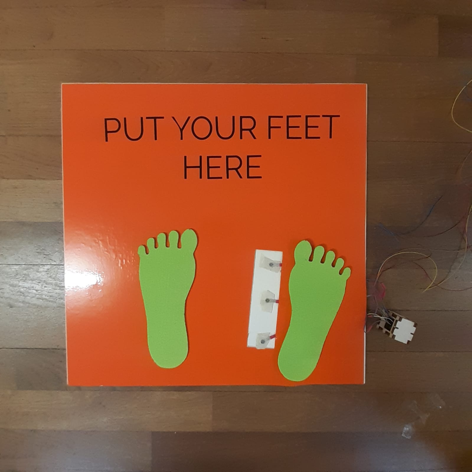
To cut the platform with the laser cutter I created on OnShape a square on the side of 49 cm in which I inserted a rectangle the size of the inscription and two rectangles that indicated the soles of the feet on which I will put the sensors. These last two have only been engraved.
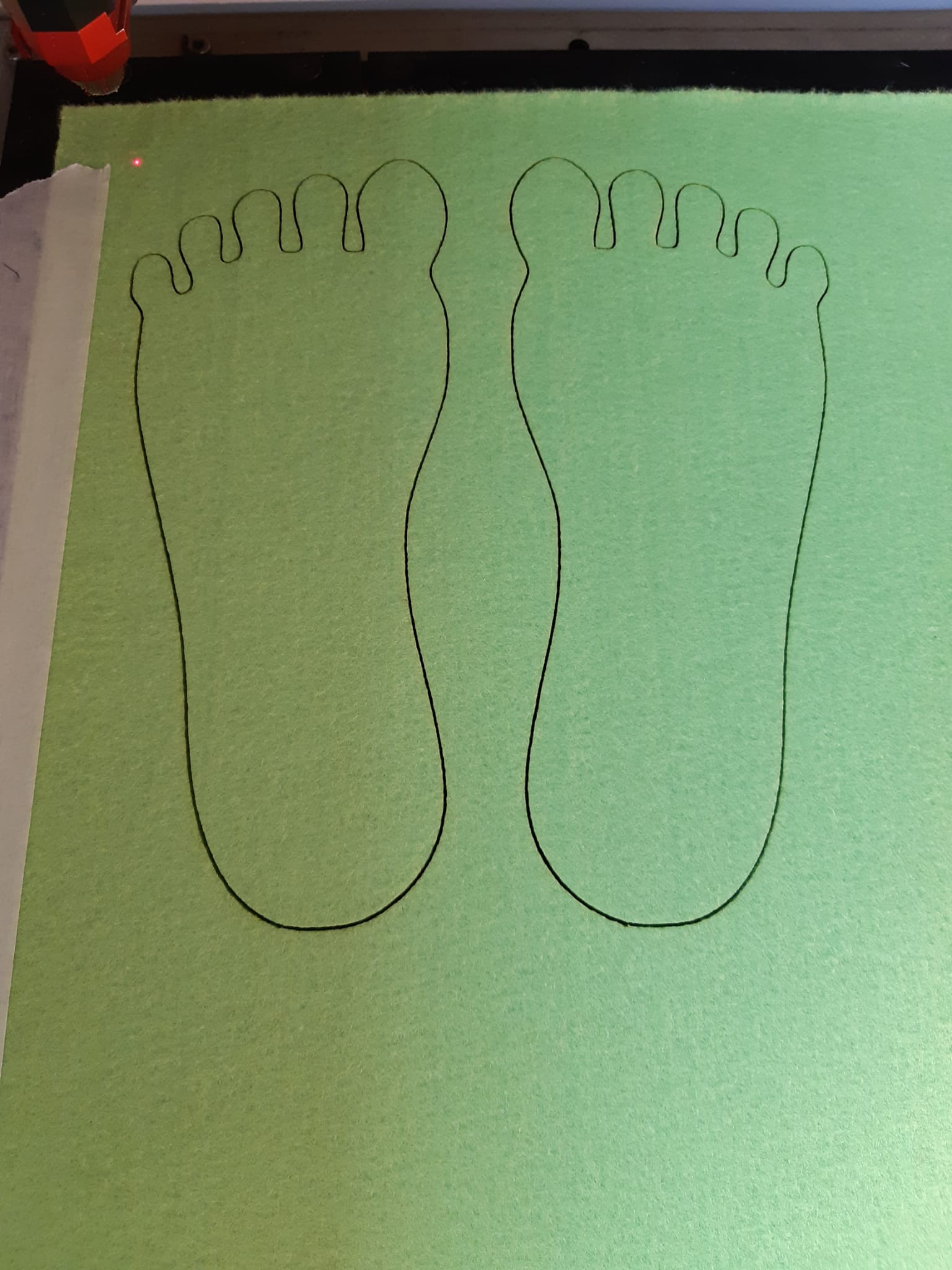
With the Laser Cutter, I also cut footprints with felt. The FSRs will go under these footprints and the baby will be placed on them.
Illustrator and Job Control
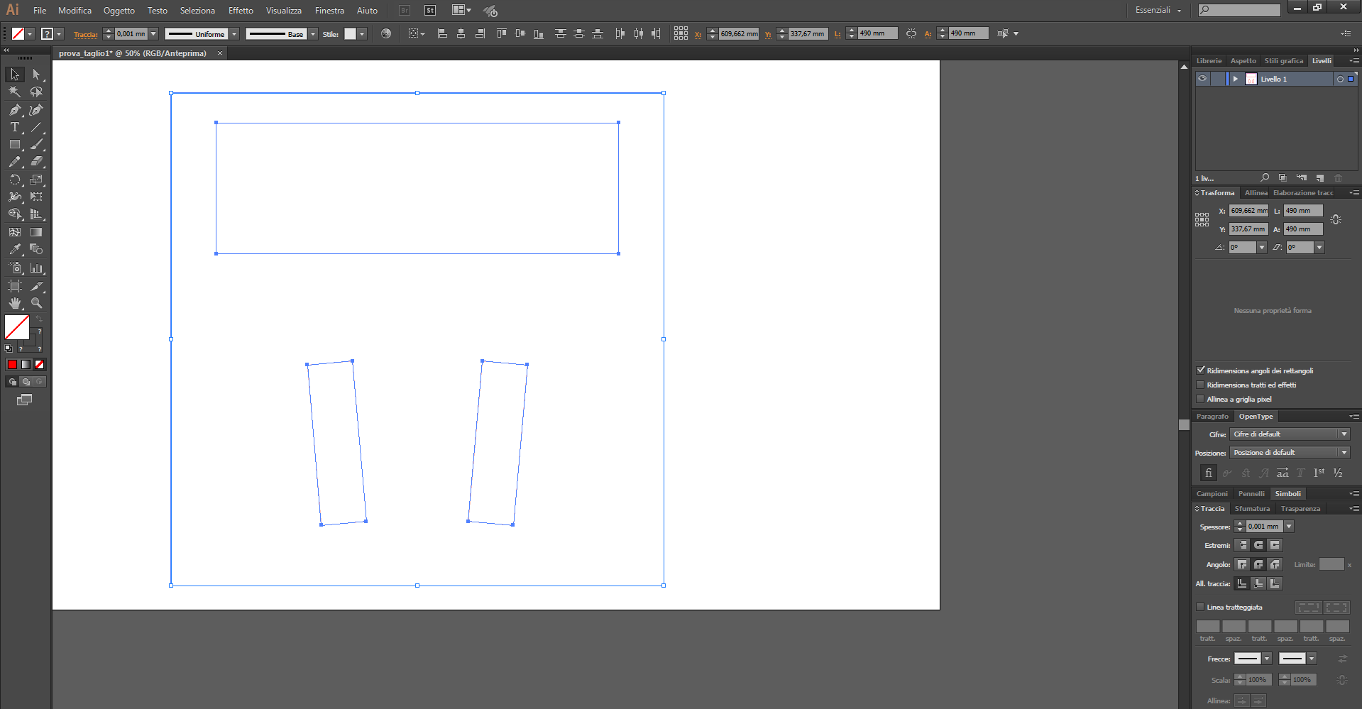
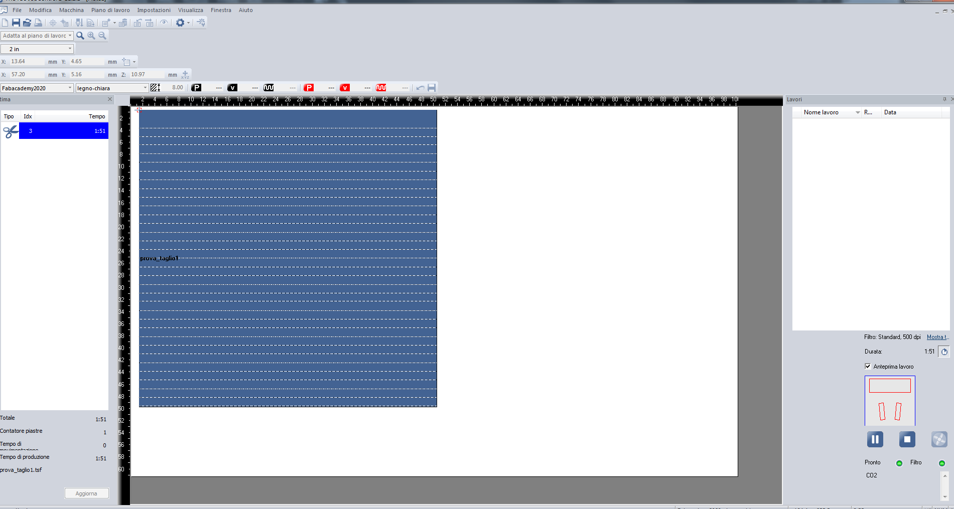
Once exported the file I inserted it on Illustrator, defined the track size (0.001 mm) and the color of the track (blue for the external rectangle and red for the internal ones) setting on Job Control these settings as those corresponding respectively to cutting and engraving.
Vinyl cutter
I used the same file for the vinyl cutter (but removing the internal rectangle) so I'm going to cut the orange vinyl that I'm going to use as coating
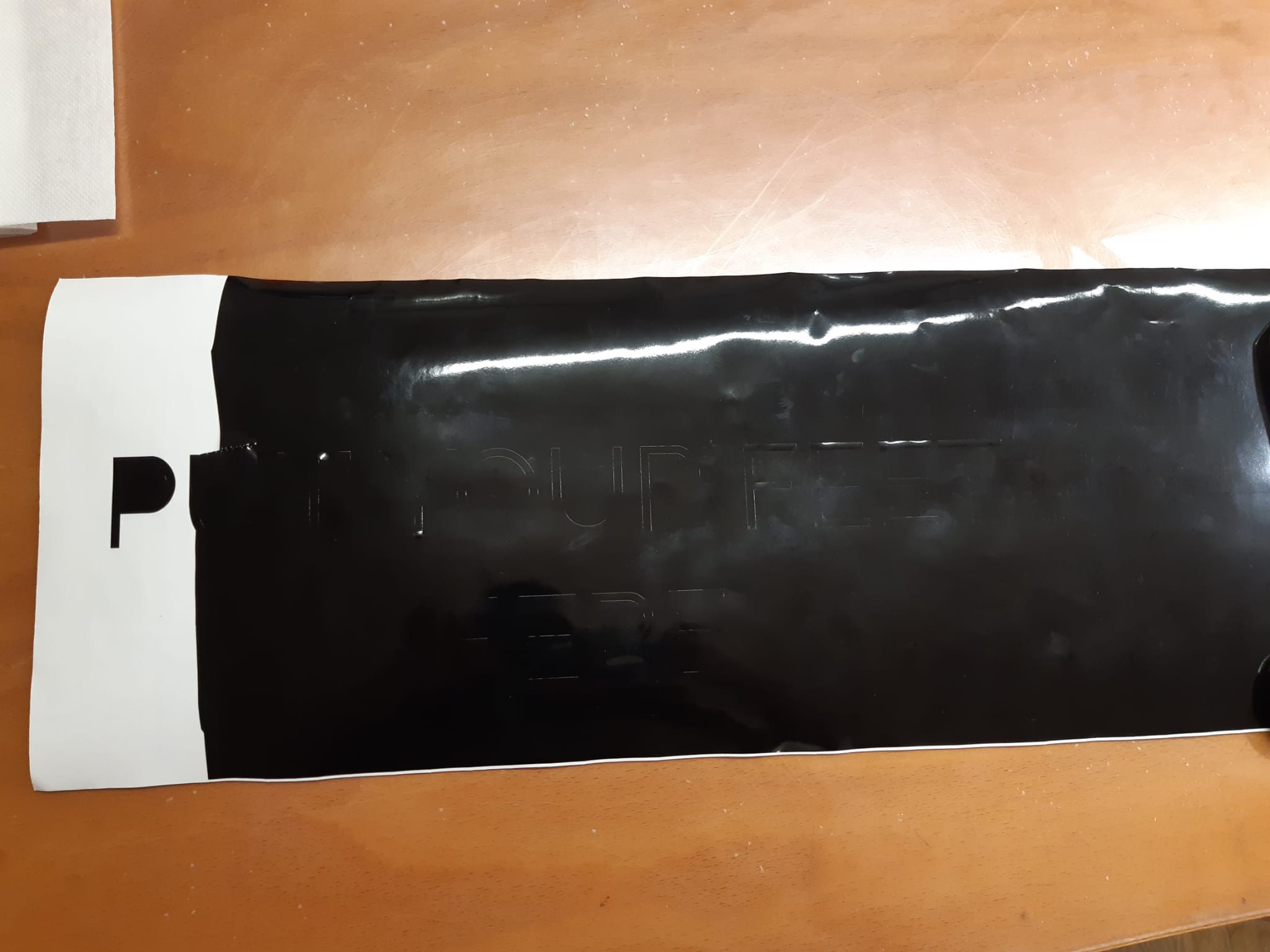
I created an inscription which I then had engraved on a black vinyl cutter vinyl, then I removed the excess black and then I put it on top of the adhesive sheet, strfinato and then removed the transparent adhesive and at the same time fixed the inscription on the orange vinyl.
Thanks to my tutor I was able to film the video of the demonstration
Improvements
I would have liked to have done a more refined project. Unfortunately, starting from zero, while also attending the master's degree and having been at home for months for the quarentina due to Covid, I could not do better (even if for me this is a great achievement!).
Surely, the first thing I will improve will be the connections between the various boards that, instead of with the cables I would do with bluetooth. I'll also insert more sensors because three are definitely not enough to get an accurate feedback of the situation, I'll do it for both feet and finally I'll create a wearable device (socks with these sensors maybe) so the detection can also be done on the move.

This work is licensed under a Creative Commons Attribution-ShareAlike 4.0 International License.