This should be my most interesting week. I graduated as an Electronics Engineer, but never got the chance to learn how to produce circuit-boards. Now using Roland SRM-20 we will learn how to mill and cut to produce the base of circuit-boards that would then have components soldered onto, the circuit-board would then be programmed.
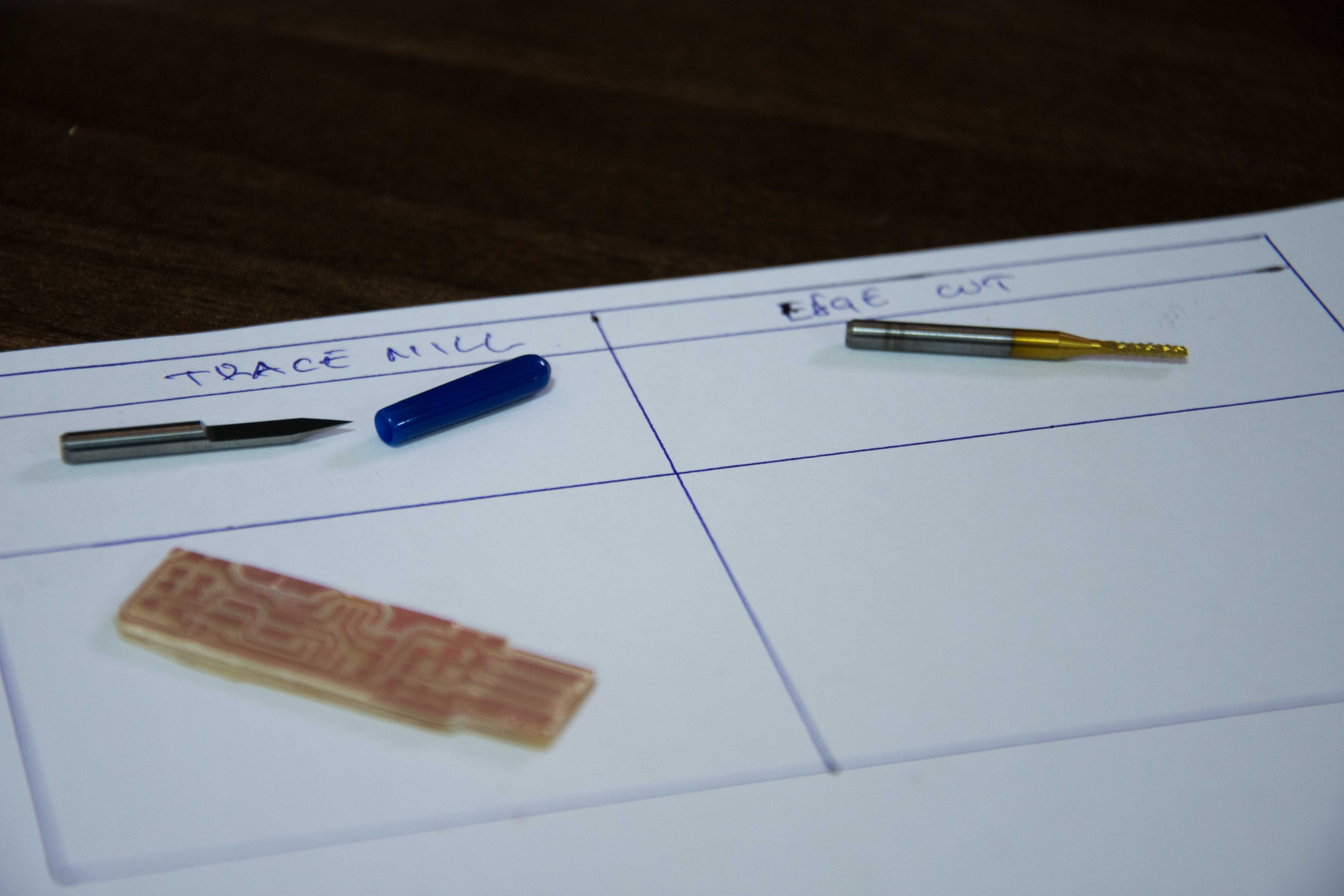
The first step would be to mill traces on the PCB to electrically connect various connectors and components to each other. Using Roland SRM-20 and a 1/64 milling bit, we will produce the following traces on the circuit-board.

The next step is to cut the board according to the outline.

The third step would be to import each file from step one and step two seperately to fabmodules.org website to convert each file to the desired format required by the machine.
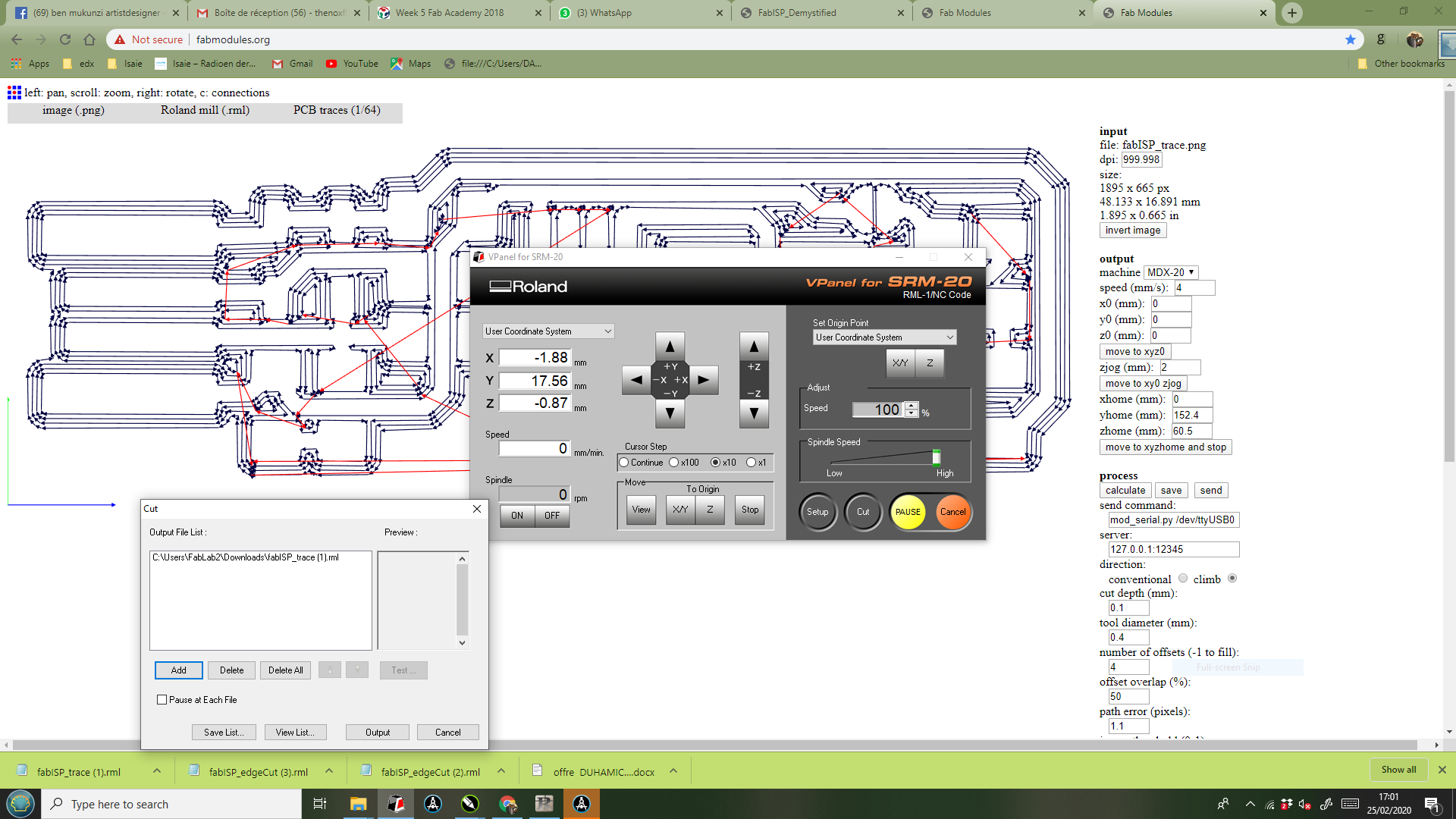
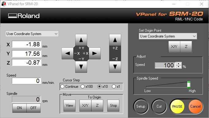
After creating the .rml file, we can prepare the machine. The first thing is to grab the piece of material where you will cut your board and paste it to the plate. To do it, we used 2 face tape, you have to make sure that, if you have more than one tape, they are not touching because putting one on top of the other can create an inclination and a bad result. Then you can connect the machine and set the origin. To do it, first set the XY coordinates. Then approach the Z axis without touching the board, release the drill and when it touches the plate fix it again. Set the Z=0 and raise it a little bit. With the setup done, close the security glass and press Cut. Then a pop-up menu will appear. There you have to delete all previous files, and add yours. When you press Output the machine will start.
After the board is done, we can launch the second file with the borders, remember to change the drill for the 1/32 and set again the Z origin. Do not reset the X and Y origin, if not it can move and your design will not be ok. If it is a little bit dirty, you can clean it with alcohol. This was the result:
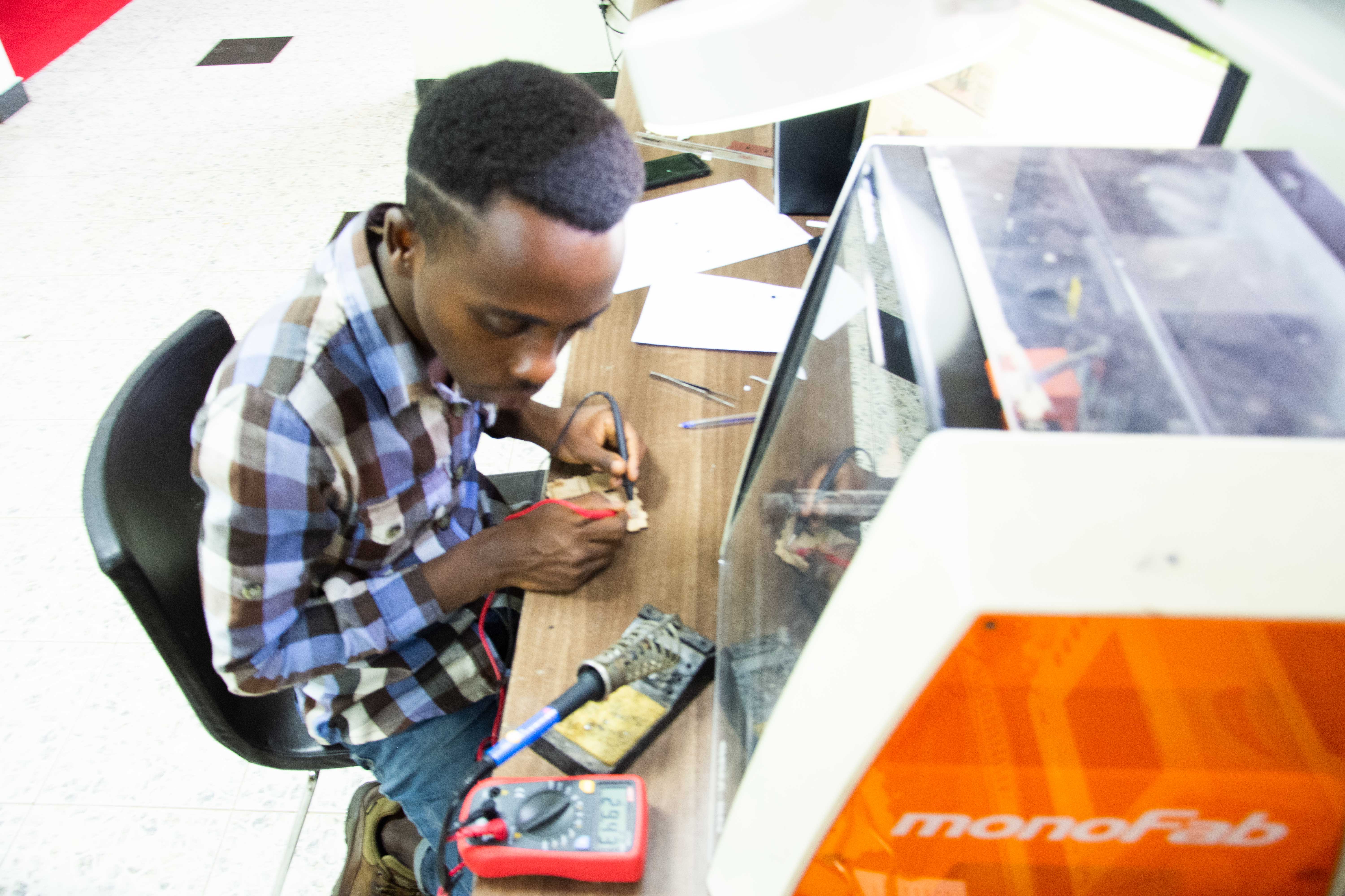
Components required: 1x - ATTiny 44 microcontroller 1x - Capacitor 1uF 2x - Capacitor 10 pF 2x - Resistor 100 ohm 1x - Resistor 499 ohm 1x - Resistor 1K ohm 1x - Resistor 10K 1x - 6 pin header 1x - USB connector 2x - jumpers - 0 ohm resistors 1x - Crystal 20MHz 2x - Zener Diode 3.3 V 1x - usb mini cable 1x - ribbon cable 2x - 6 pin connectors