Electronic production
Assigment objectives
- Week 4 Group assignment
- Design the PCB trace and cutting using MOD
- Set up the software and trace and cut
- Add component on the PCB
- Test and add the software
Summary
This week we were tasked to characerizethe specification of our PCB production and to make an in-circuit programming, and program it. The current report is that due to some technical challenges, the work in not yet done, Due to the breaking of our tools and the inability to solder correctly particularly the Microcontroller
Group assigment: Characterize the specification of the PCB
The goal of this task was to test the accuracy of our machine, we use various tools with different parameters to determine the level of accuracy, we use the 1/32, 1/64 and 0.010 tool, and the test design is provided by
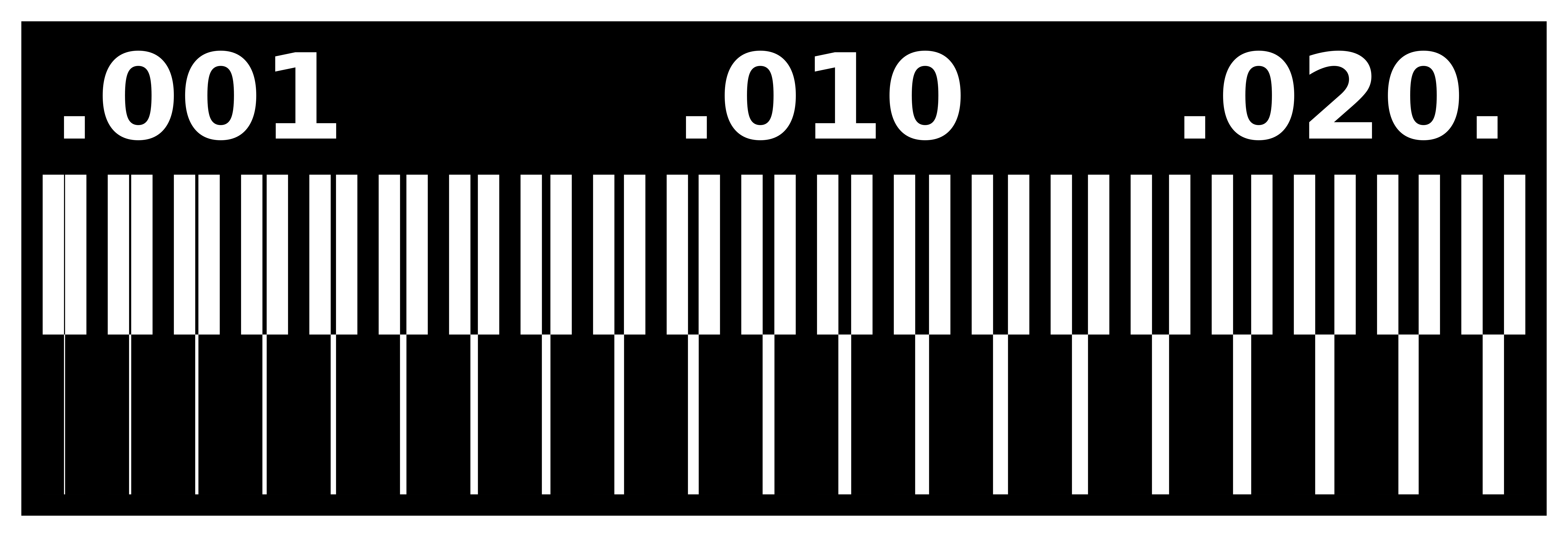
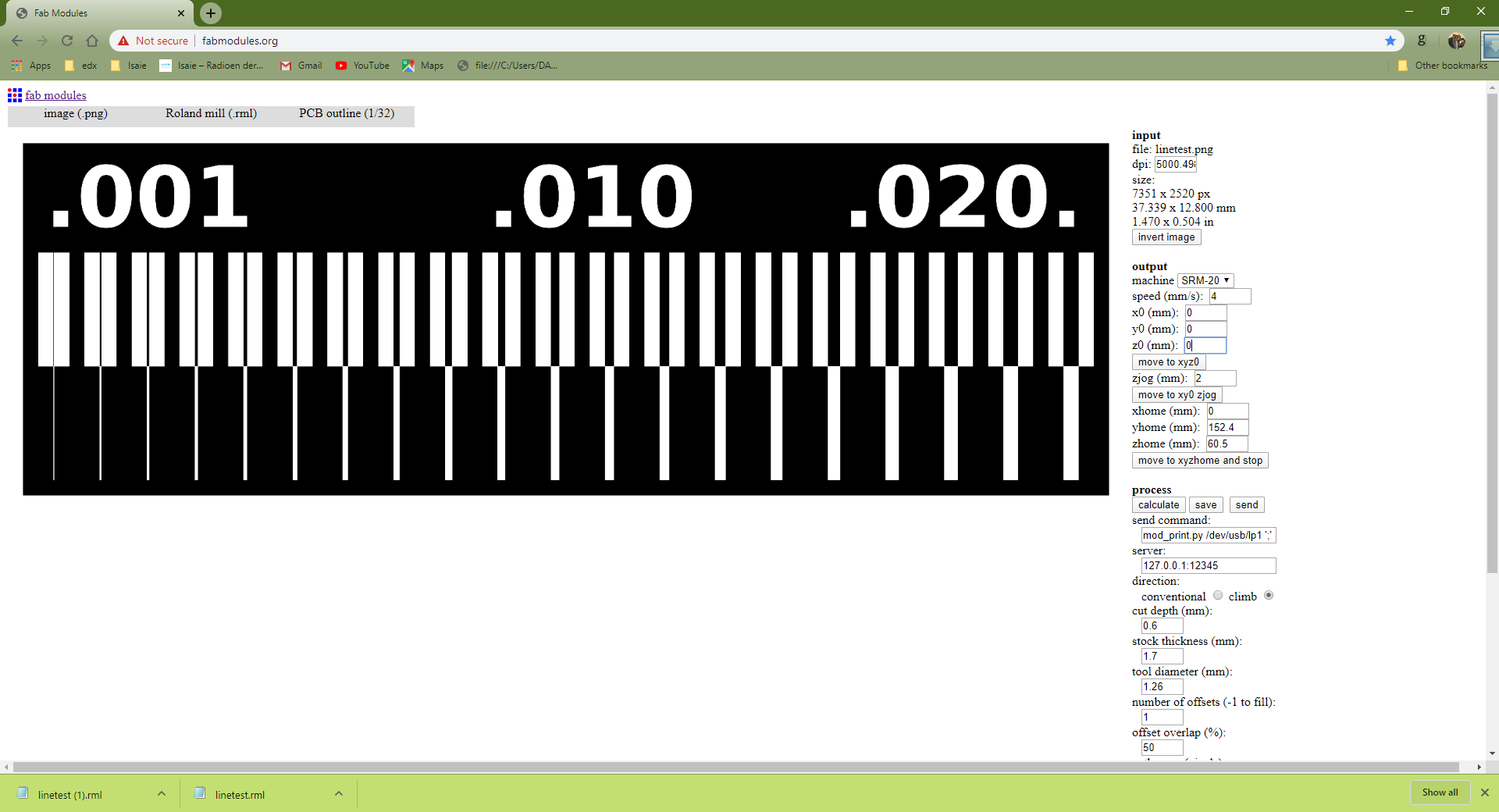
We started by testing the 1/32 linetest, we entered the png in the fabmodules, and adjusted the settings, due to our tools being brokken we used first the 1.18 and 1.26 so we had to change that parameter in the tool diameter, moving from 0.78, to first 1.18 then 1.26, then when we pressed the option calculate, you can see that the trace is not accurate, other details are found in the images below

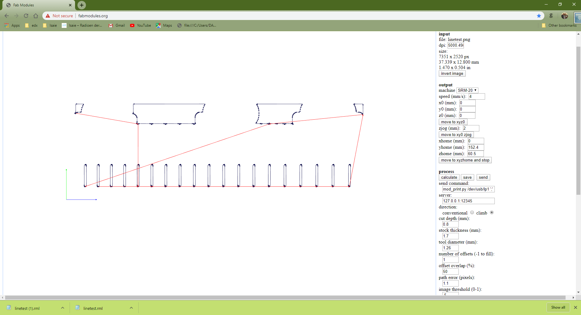
Unfortunately when we wanted to trace in the machine the tool broke down
The next was the 1/64, where with this one,there was no adjustement and when we calculate we find a very improved precise trace
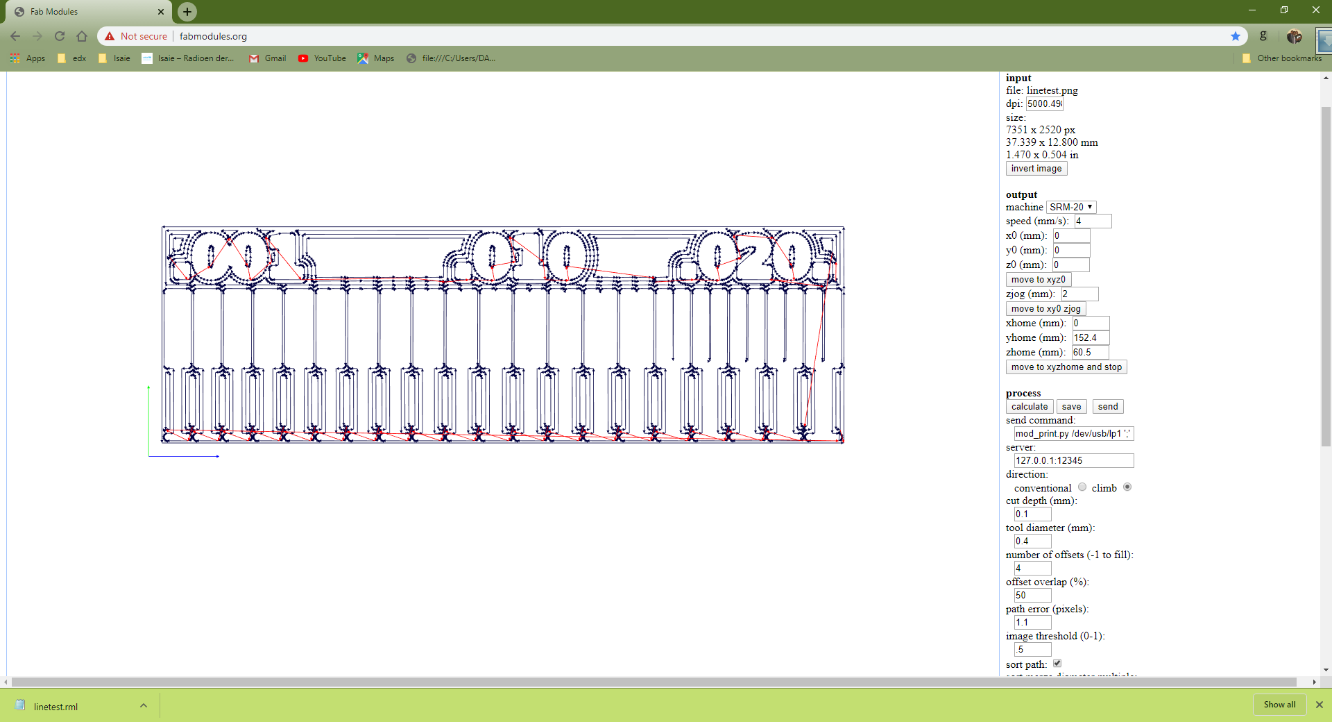
The last test we wanted to conduct was on the 0.010 tool, in fabmodules apart from the normal parameters there was not need to change the parameters excpet for the trace depth which is 0.1, when we calculate we find an even more precise trace

Design the PCB trace and cutting using MOD
First we had to open mod, using the fabmodules, then we load the pgn image, load the PCB trace file, after we precise the process: Rolland milling. Afterwards we precise the precision: 1/64 inch
Once the precision is set we must select the device, ours is SRM-20, then set the origin parameter x,y, and z to 0
To trace we do not make any changes to the default settings but rather press calculate, Calculate calculate where the SR-20 machine will trace on the PCB, the picture below showcase the result of calculate.
if we are satisfied with the result from calculate then we save, and the file is saved on the computer
Set up the software and trace and cut
Add component on the PCB
Test and add the software
Challenges encountered
The first challenge was the tools were breaking, especially the 1/32 cutting tools, as we started to cut, the cutting would get stuch and immediately the tool will break
Another challenge encountered was soldering, it requires some experience and especially soldering the IC