

Read a microcontroller data sheet Program your board to do something, with as many different programming languages and programming environments as possible Optionally, experiment with other architectures to accomplish this assignment i used hello board i created in week6 (Electronics device)
• High Performance, Low Power AVR® 8-Bit Microcontroller
• Advanced RISC Architecture
– 120 Powerful Instructions – Most Single Clock Cycle Execution
– 32 x 8 General Purpose Working Registers
– Fully Static Operation
• Non-volatile Program and Data Memories
– 2/4/8K Bytes of In-System Programmable Program Memory Flash
• Endurance: 10,000 Write/Erase Cycles
– 128/256/512 Bytes In-System Programmable EEPROM
• Endurance: 100,000 Write/Erase Cycles
– 128/256/512 Bytes Internal SRAM
– Programming Lock for Self-Programming Flash Program and EEPROM Data Security
• Peripheral Features
– 8-bit Timer/Counter with Prescaler and Two PWM Channels
– 8-bit High Speed Timer/Counter with Separate Prescaler
• 2 High Frequency PWM Outputs with Separate Output Compare Registers
• Programmable Dead Time Generator
– USI – Universal Serial Interface with Start Condition Detector
– 10-bit ADC
• 4 Single Ended Channels
• 2 Differential ADC Channel Pairs with Programmable Gain (1x, 20x)
• Temperature Measurement
– Programmable Watchdog Timer with Separate On-chip Oscillator
– On-chip Analog Comparator
• Special Microcontroller Features
– debugWIRE On-chip Debug System
– In-System Programmable via SPI Port
– External and Internal Interrupt Sources
– Low Power Idle, ADC Noise Reduction, and Power-down Modes
– Enhanced Power-on Reset Circuit
– Programmable Brown-out Detection Circuit
– Internal Calibrated Oscillator
• I/O and Packages
– Six Programmable I/O Lines
– 8-pin PDIP, 8-pin SOIC, 20-pad QFN/MLF, and 8-pin TSSOP (only ATtiny45/V)
• Operating Voltage
– 1.8 - 5.5V for ATtiny/45V/
– 2.7 - 5.5V for ATtiny/45/
– ATtiny25V/45V/85V: 0 – 4 MHz @ 1.8 - 5.5V, 0 - 10 MHz @ 2.7 - 5.5V
– ATtiny25/45/85: 0 – 10 MHz @ 2.7 - 5.5V, 0 - 20 MHz @ 4.5 - 5.5V
• Industrial Temperature Range
• Low Power Consumption
• 1 MHz, 1.8V: 300 µA
– Power-down Mode:
• 0.1 µA at 1.8V
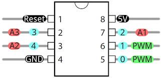
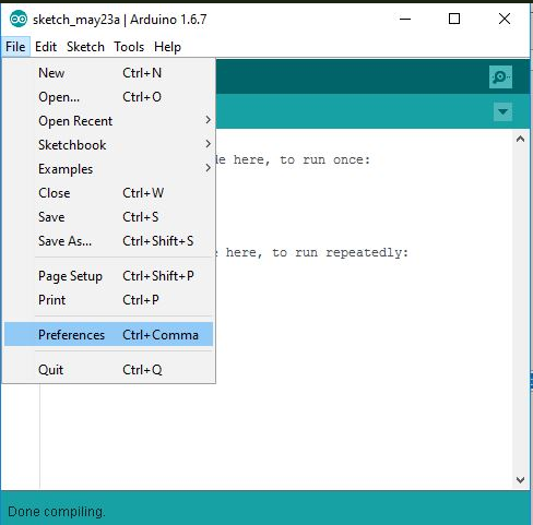
for programing at the first time i used Arduino IDE 1.6.7 so by default ATtiny45 we need to add ATtiny board in ardunio board manager, here there is the procedures open File > preference
Find the “Additional Boards Manager URLs” field near the bottom of the dialog and copy and paste
below link and fill it in the gap as seems on image below
https://raw.githubusercontent.com/damellis/attiny/ide-1.6.x-boards-manager/package_damellis_attiny_index.json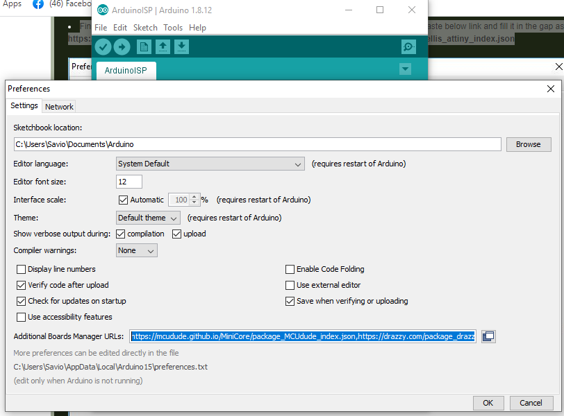
After copying the link I changed to Tools and went to Board: and selected Boards Manager
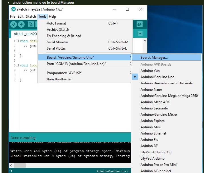
A Board manager window opened-up I searched for ATtiny and installed the boards for it.
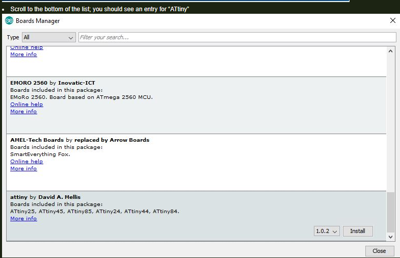
From here I could select ATtiny boards.
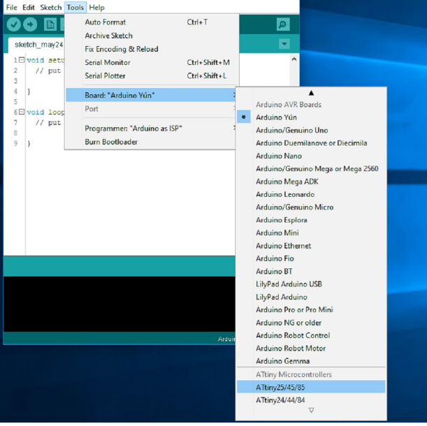
close the dialog box then select the processor, clock size and a programer thenk click burn bootloader if it is the first time
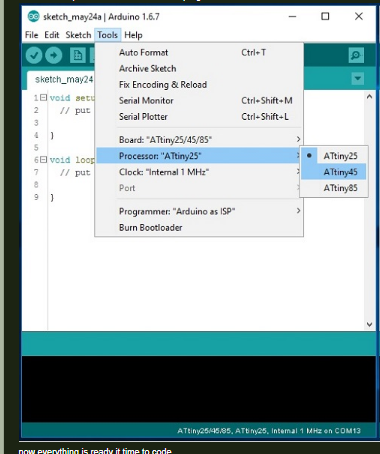
Everything is ready it time to make programming
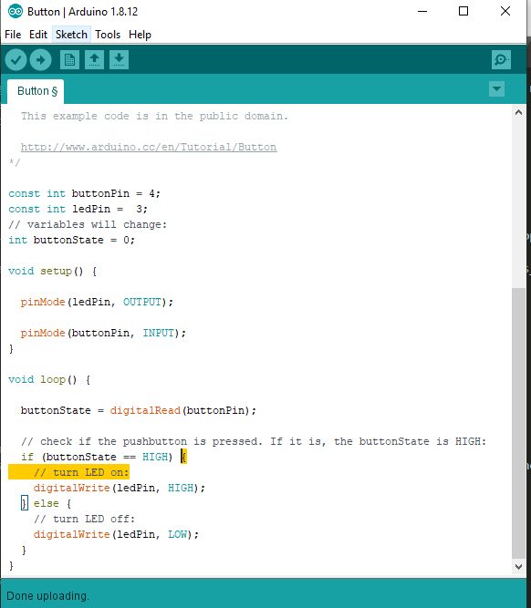
The original files used for this assignment can be downloaded here.