Make an in-circuit programmer by milling and stuffing the PCB, test it, then optionally try other PCB processes
After learning the Electronic production, I started, how I can make my circuit. With the Brian"'design FablSP.
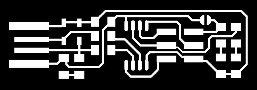
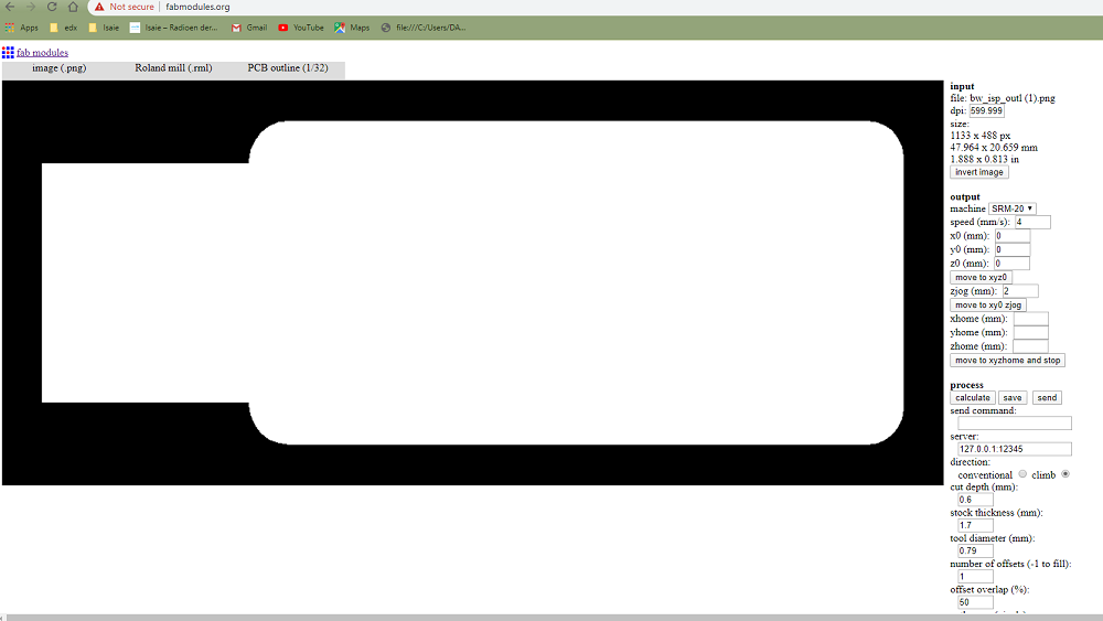
I used these image with the ROLAND milling.I is trace for FabISP
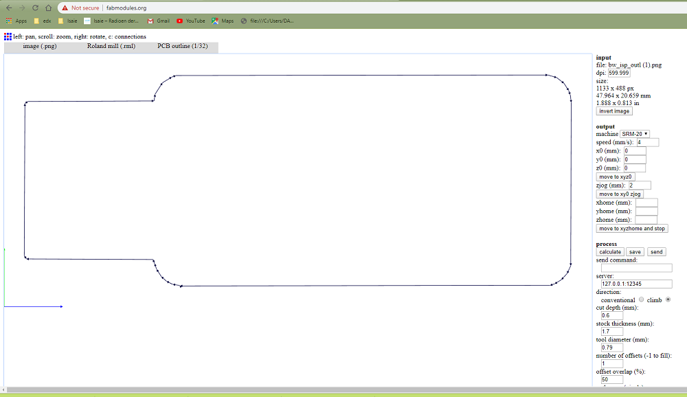
After making the Trace, I made the EdgeCut. I would like to remove my circuit to PCB

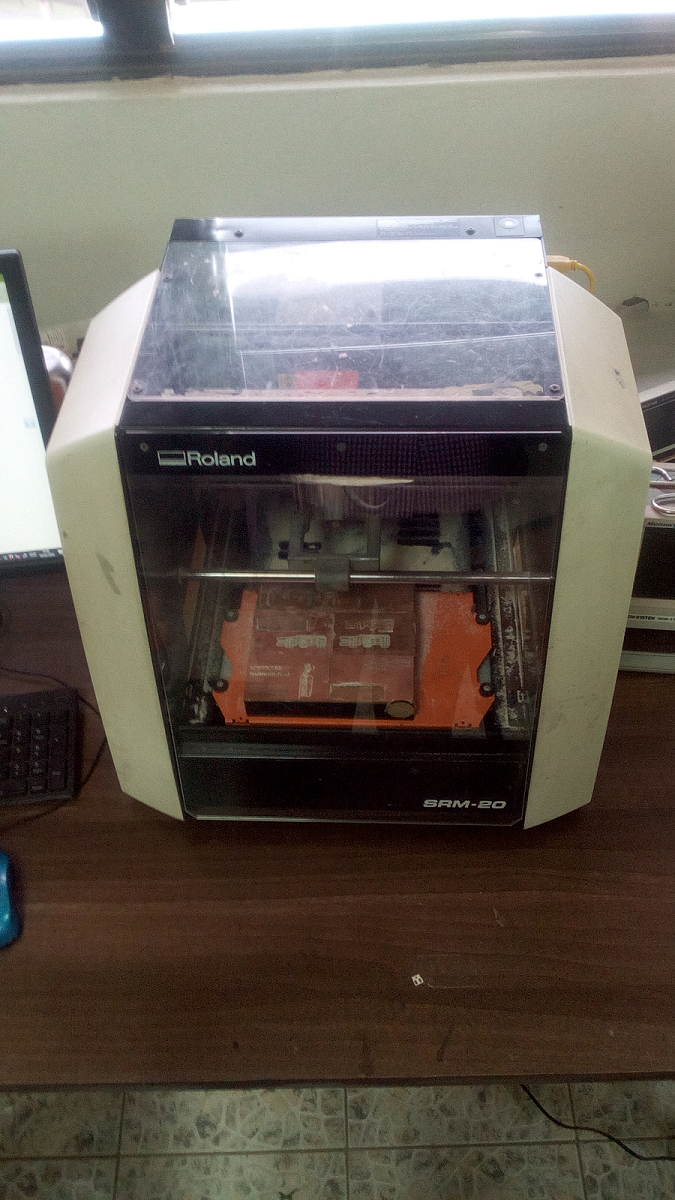
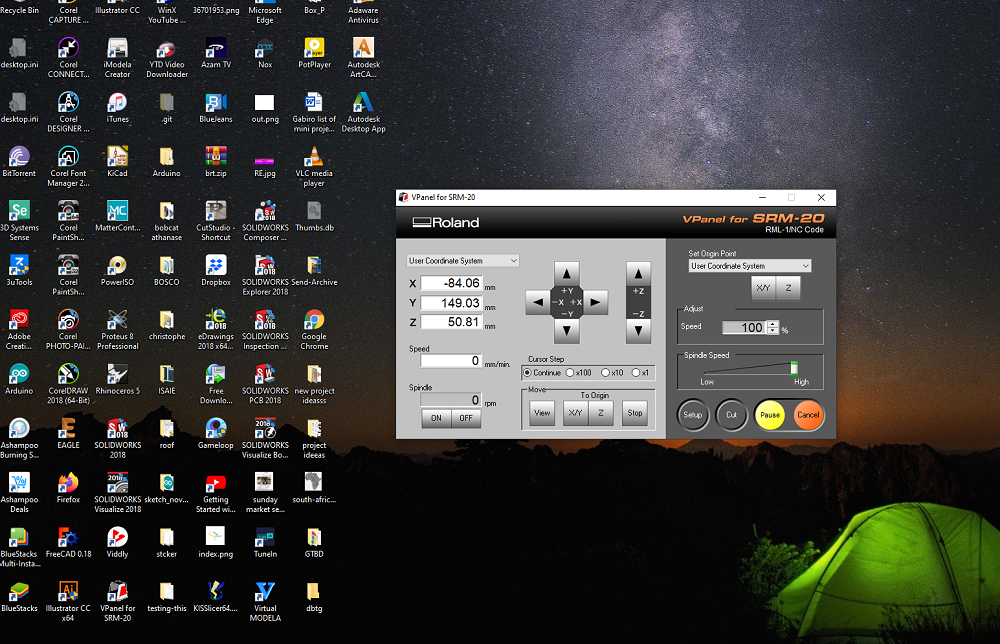
In our FabLab Rwanda we have SRM-20 monofab milling machine.
I was not easy because, I made this work for the first time. it was first I used KiCAD software for drawiung. I started to wacth video tutorial on You tube and then I began to draw! I was having the images which is converted in PNG. I used fabmodules to convert fabISP images to rml. I choosed PNG imsage input, on output format I choosed Roland mill(.rml), and on process I choosed PCB traces(1/64). And continued selecting on machine I choosed SRM-20, after all setting you see bellow I clicked on Calculate for converting it.
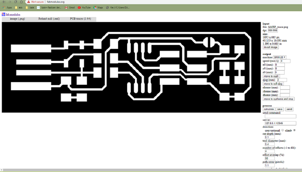
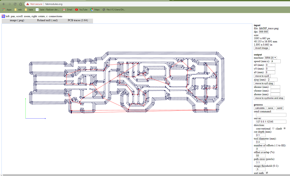
After calculating the image, I found this image you see bellow which is shown the line like that. And I clicked save for download.
And then I took the EdegCut image which is save in PNG. I made the same way like to make the PCB trace above except I selected the PCB outline in the process
Here I calculated the outline of the PCB.
Here we have software which is called VPanel for SRM-20. I switched on when I was starting to mill my work.
This is the board after cutting it.
Here is a lillte bit of zoom to see it clear.
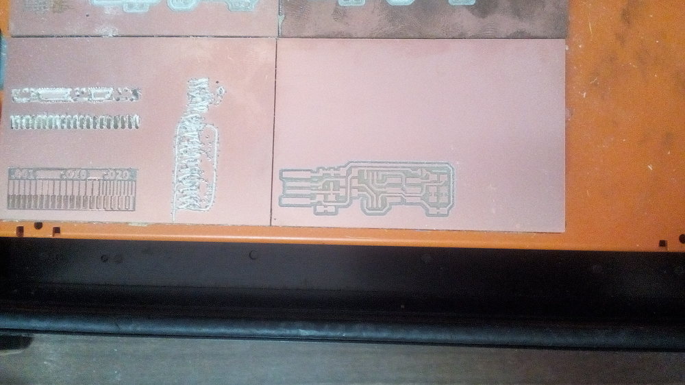
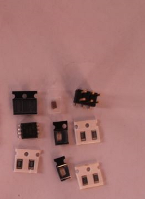
After milling I removed my pcb board. then I startd to solder components on it

1.ATtiny 45
2.2x499 Ohm resistor
3.2x2kohm resistors
4. 2x49 Ohms resistor
5. zener
diode
6. red led
7. green led
8. 100nF capacitor
9. 2x3 pin leader
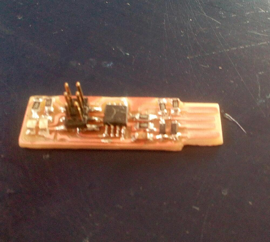
I am not expert to solder but I learnt it now, I can do it well. when i was soldering there re some componets damaged cause of the hitting. I replaced it. now it is fine
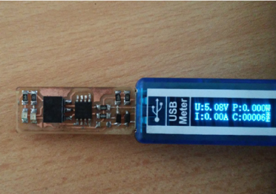
After soldering, I checked my production if there is problem for connection. I connected to the multimeter for verifying that it is misconnection or bad connected trace. I connected the program on the computer.
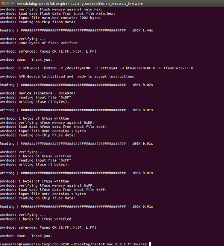
I downloaded the firmware to be loaded in the programmer. I run make flash in terminal to erase the target chip, and program the its flash memory.
The original files used for this assignment can be downloaded here