Electronics Production
Milling PCBs
the invention of Printed Circuit Boards (PCBs) was a major breakthrough regarding the size and wiring of complex circuits, where instead of manually connecting the components of a circuit with regular wires, one would print the board first and then solder the components to to the wires saving space, time, and materials.
Therefore, it is really important to learn how to design and create your own PCB layouts.
At first, we will start with creating a file for the PCB we want to make, for this week, we will make an in-circuit programmer, and solder the components on it. Luckily, the layout is ready as a png file, which supported with fab modules.
Step one:
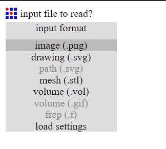
Go to Fab Modules
Step Two:
Click on "input format" and choose: "image (.png)", and choose the traces layout for the circuit.
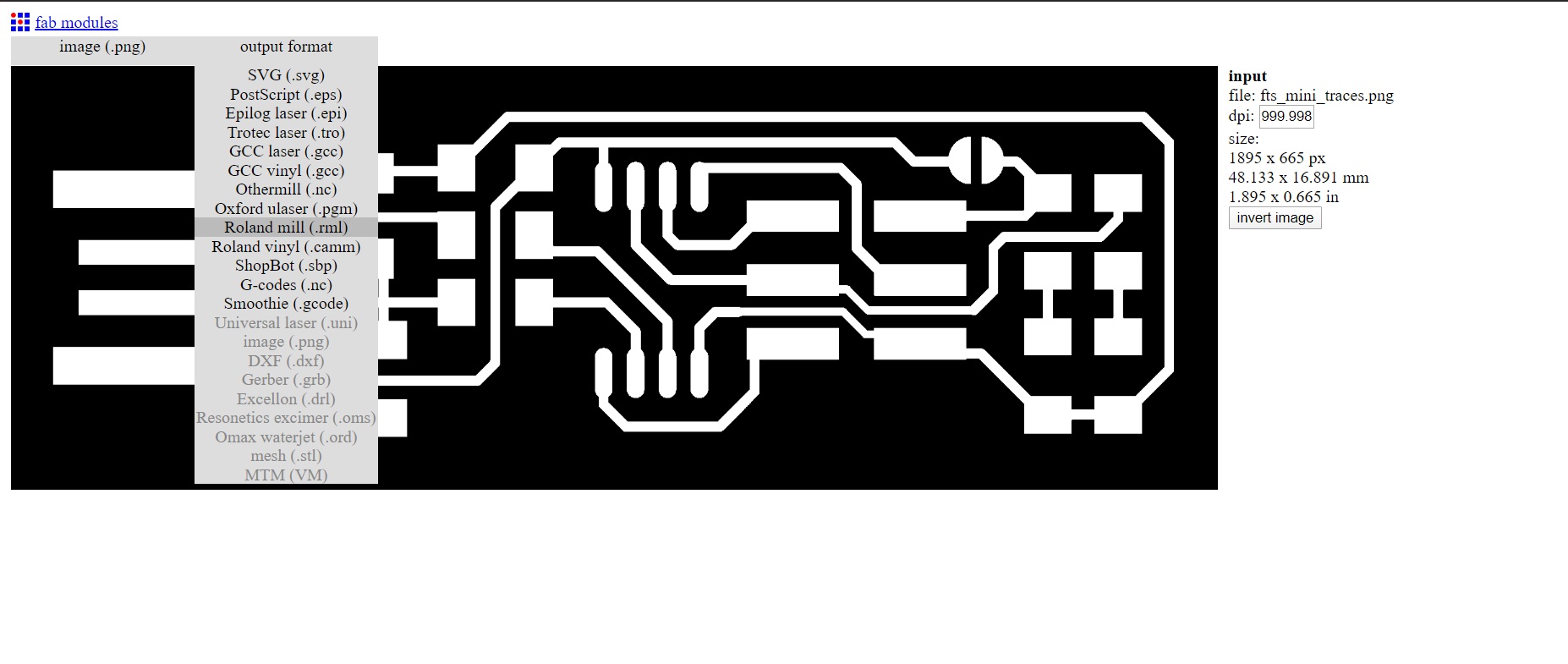
Step Three:
Click on output format and choose "Roland mill (.rml)".
Step Four:
Click on process and choose "PCB traces (1/64)"
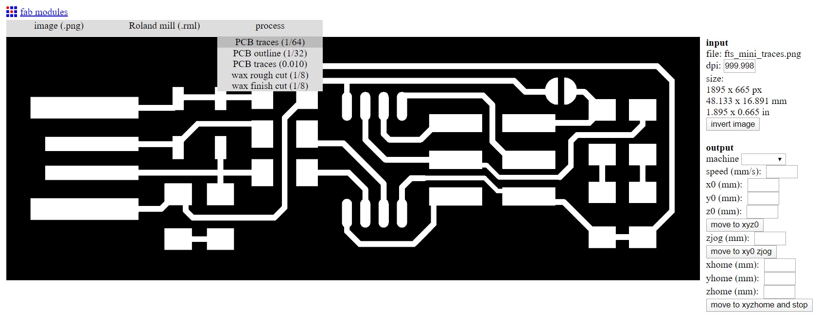
Step Five:
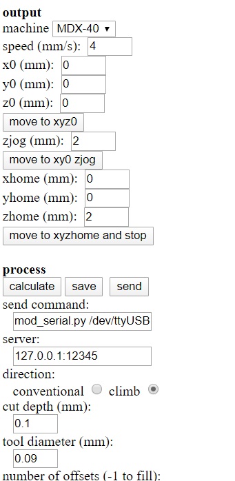
On the right panel, choose the machine type first, and then fill the parameters as follows:
Step Six:
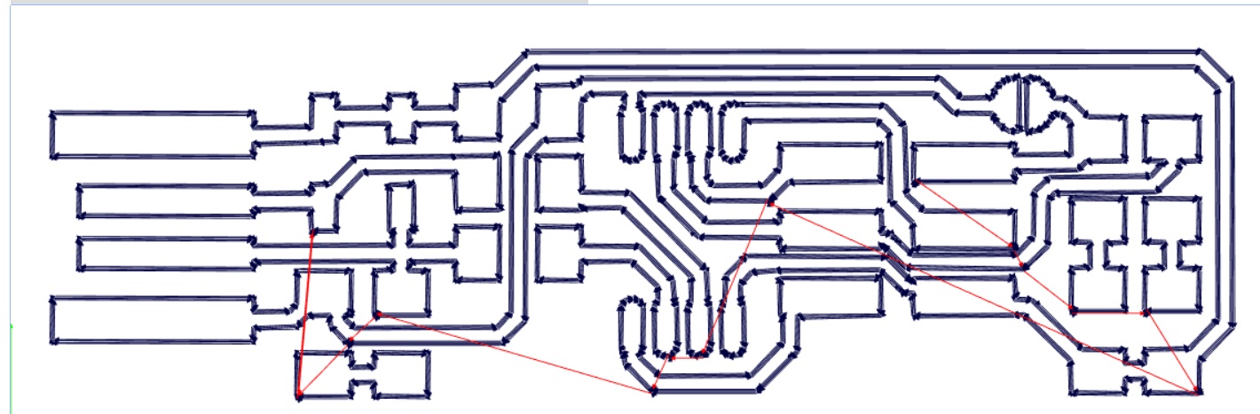
Press calculate, and wait for it to load the full path the CNC machine will follow.
Step Seven:
Once it finishes, press save and save the file.
Now we have the file ready and we should proceed to setting up the machine and recalibrating it.
First, we have to put the copper board on the machine using double sided tape. The reason behind that is that there would be arching in the board witch would cause inconsistant results.
After that, we have to recalibrate the machine in order to specify the the exact point on the board to be our origin. To do that, we choose the axis we want to move, and then we start rotate the rotery until we reach the desired point, and hold the origin button on the machine.
To calibrate the Z-axis, we first have to choose the Z-axis calibration head. Then, we insert a probe into the machine and put the other end on top of the bed, then, we navigate the machine to be on top of the calibration probe, and choose Z0 Sense button.
After that, we set the spindle speed to 5500rpm, and then start the machine.
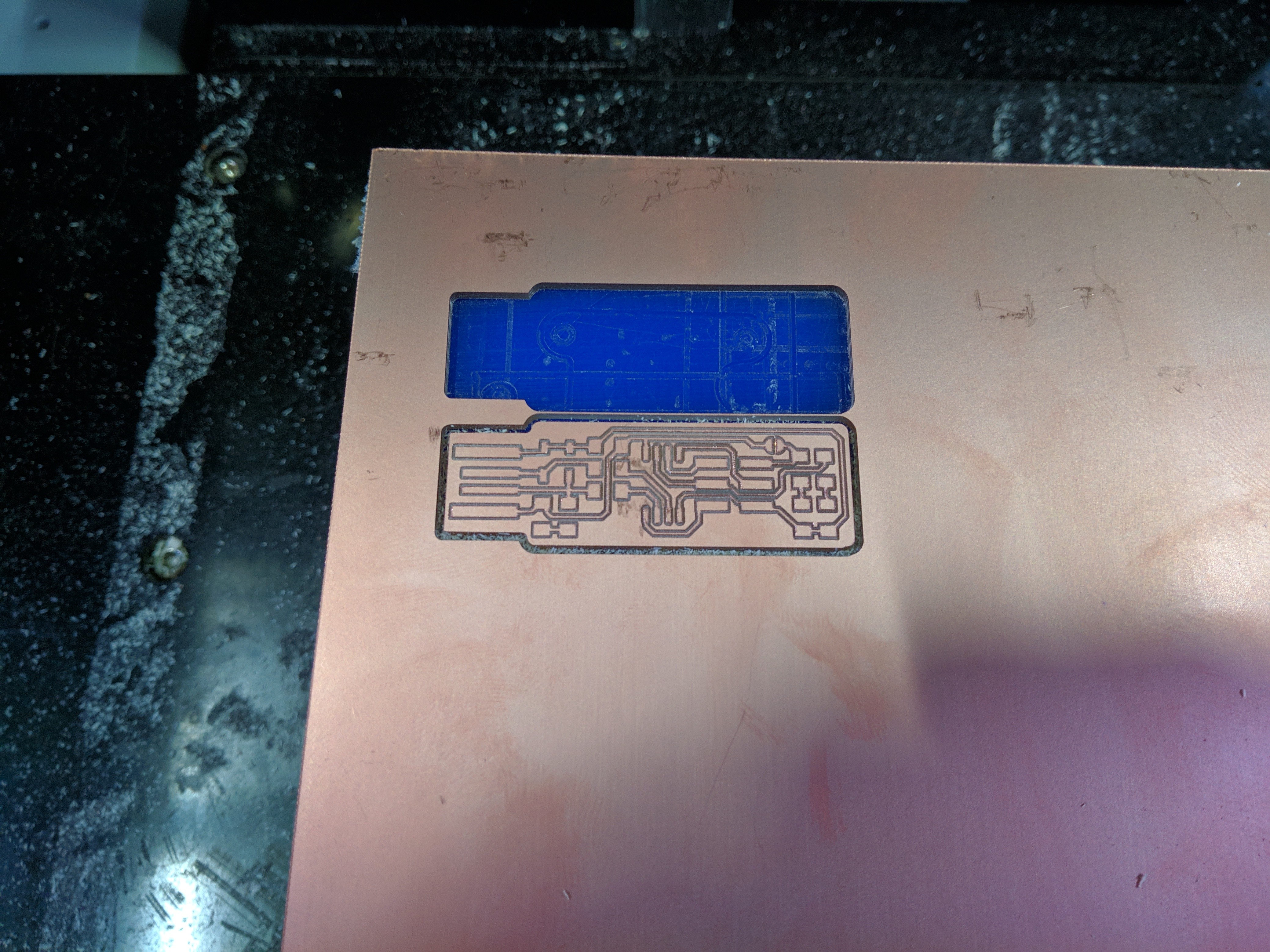
This is the finished piece, without any components on it.
After I got the schematic for the circuit with its components, I soldered them, while checking for bridging or any short circuit using the continuity function on the multimeter.
And this is the finished product.

Group Assignment
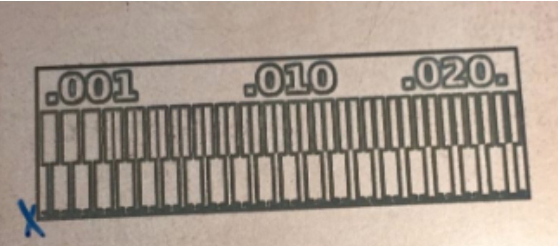
As for the group assignment, we had to characterize the design rules for the machine in the lab (Roland MDX-50).
To do that, we first prepared a file using Fab Modules
Once the we prepared the tracing and the cutting files, we loaded them to the machine using Roland Software (VPanel)
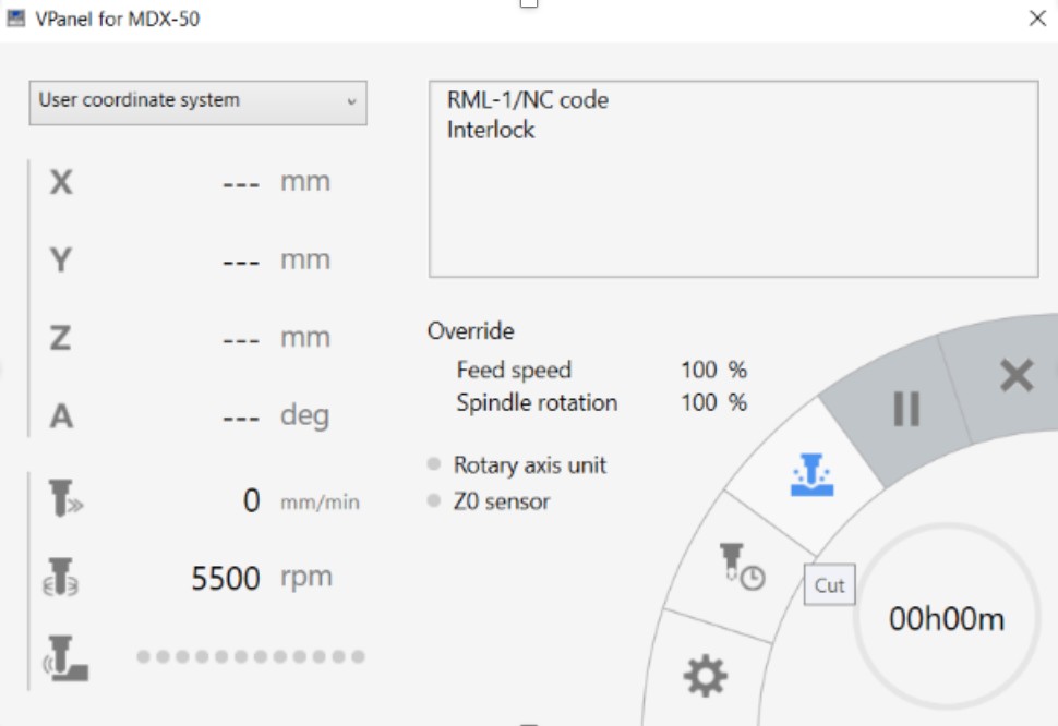
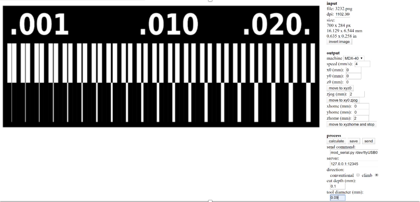
The finished PCB had traces down to 0.001mm: