

Week 8 Embedded Programming
This week we will learn coding with electronics, it will take long time to practice but I think it will be fun to learn.
Weekly Assignment
- Group assignment: compare the performance and development workflows for other architectures
- Individual assignment: read a microcontroller data sheet; program your board to do something, with as many different programming languages and programming environments as possible
Individual assignment
Datasheet is a document that summarizes the performance and other technical characteristics of a product in details that allows engineers to understand the role of the component in the overall system. Typically, datasheet is created by the manufacturer.
Read ATtiny44Datasheet
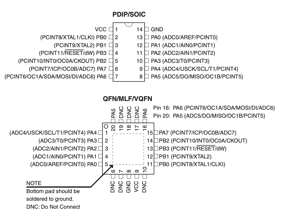
AT tiny 44 Pin Descriptions
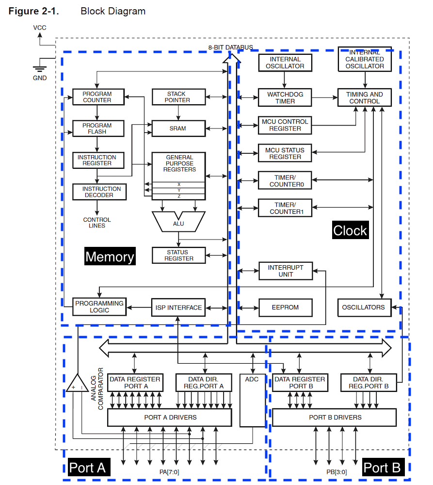
Main features of AVR 8bits (ATtiny24/44/84) microcontroller:
AVR enhanced RISC (Reduced Instruction Set Computer) Architecture: better real time performance; generally have lower cycles per instruction (CPI) than a complex instruction set computer
Play with arduino UNO board
Aduino Fade Led
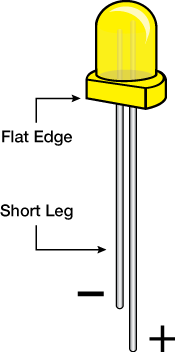
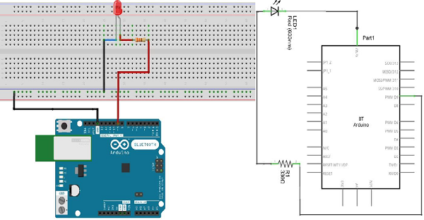
Connect bread board, 1 × 330Ω resistor, led and arduino Uno like this:
Connect the short leg of led to ground.
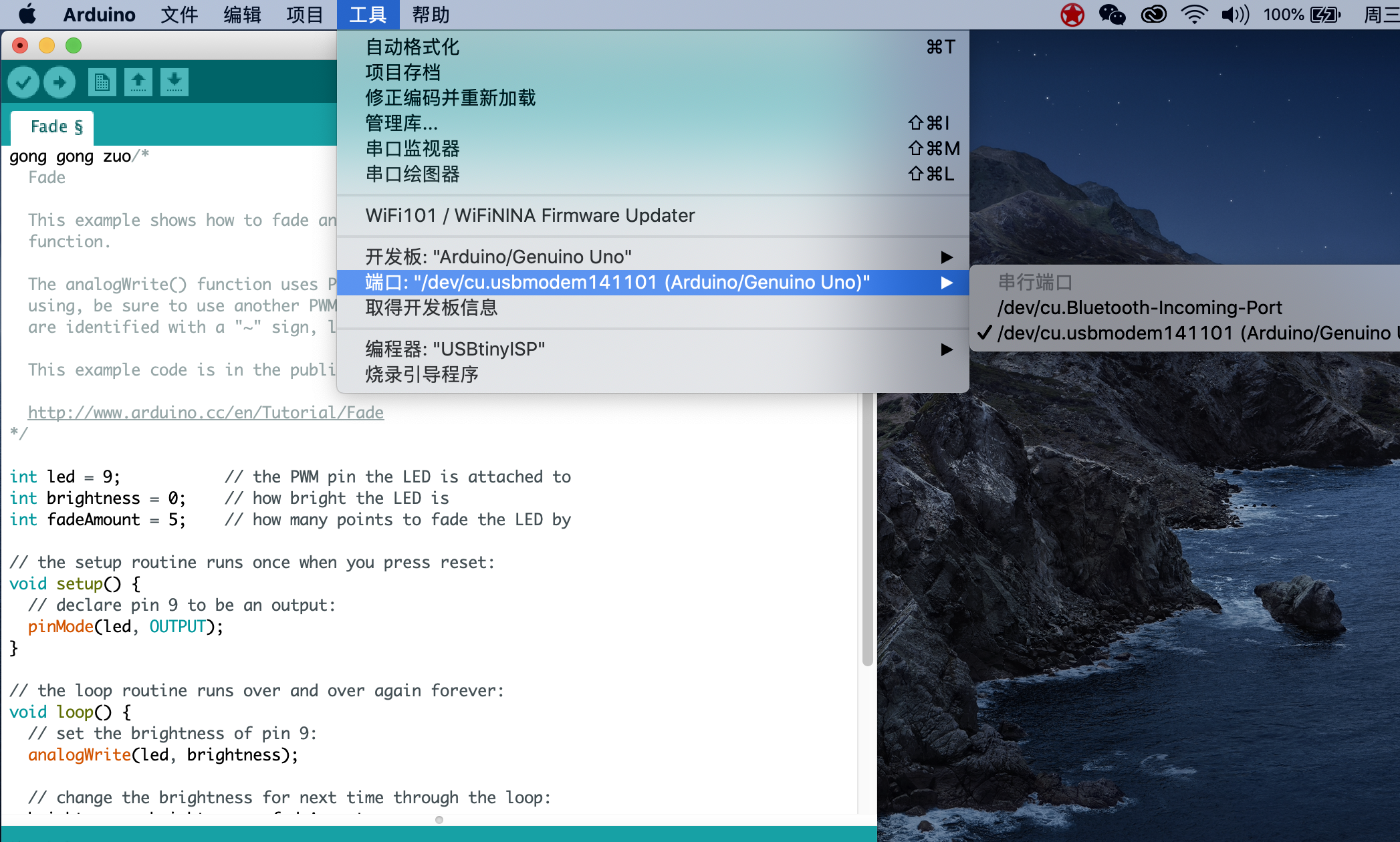
Chose arduino UNO board and port.
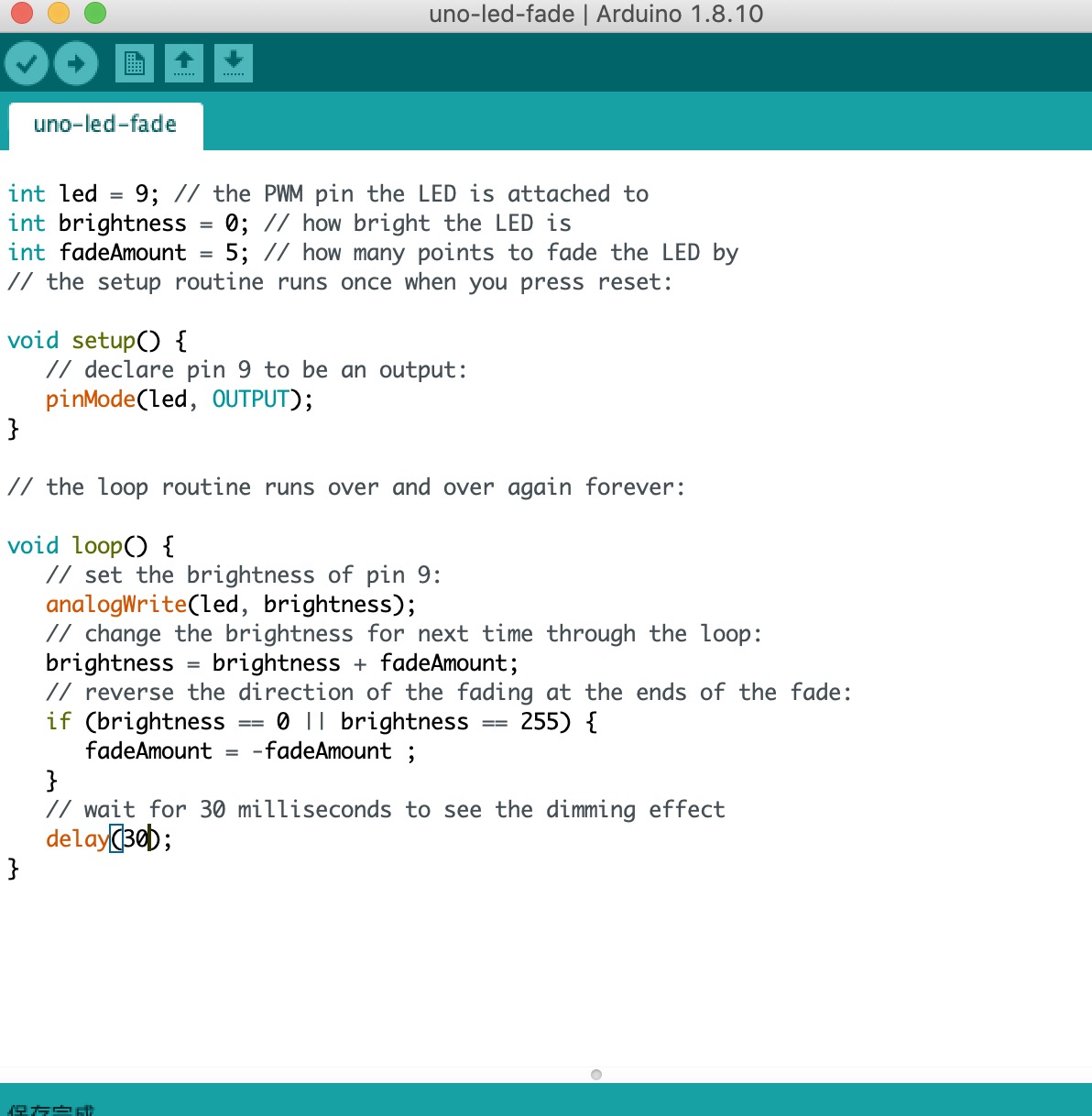
Fade led code:
Video:
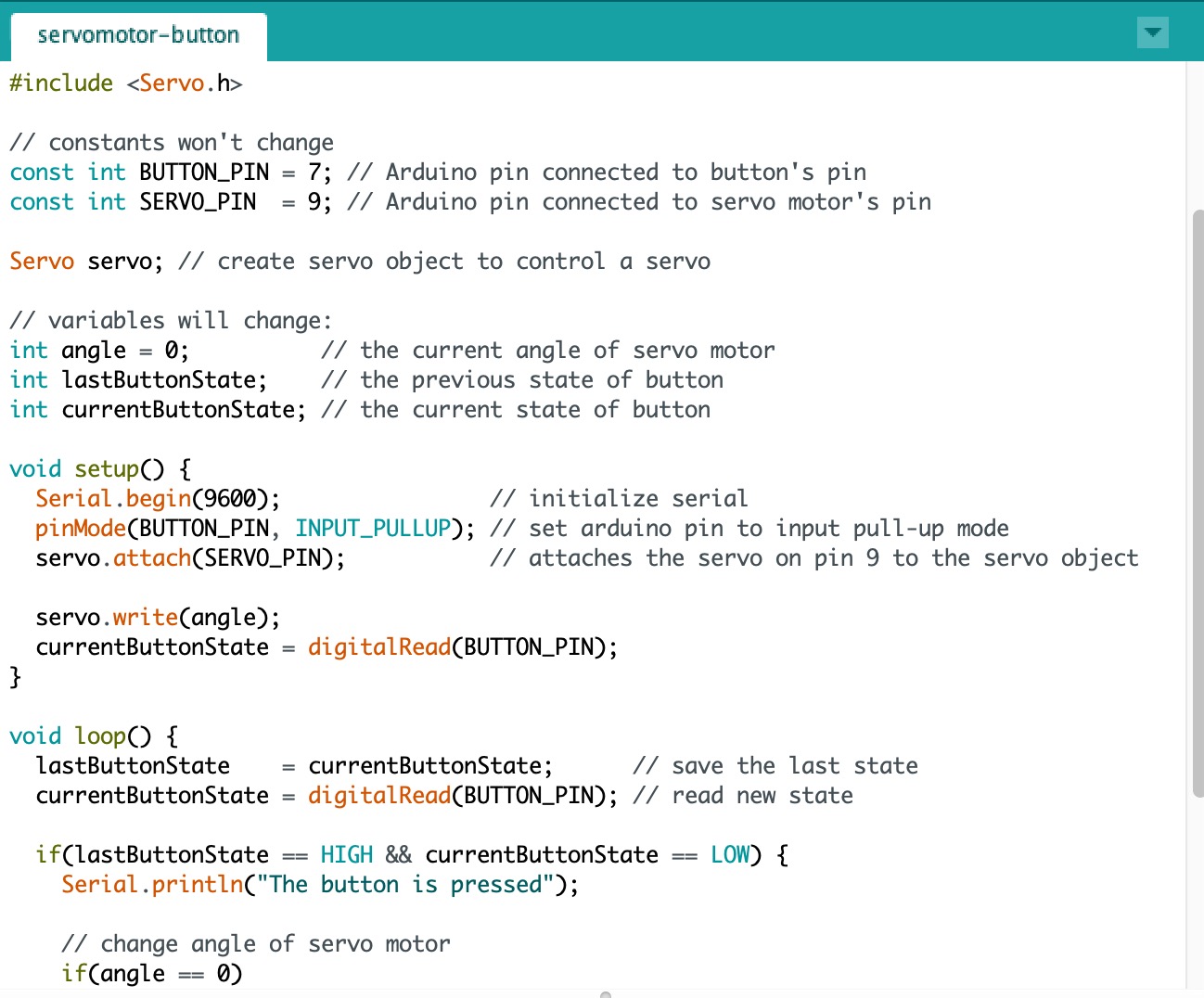
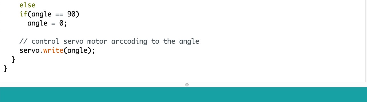
Arduino Buton control Motor
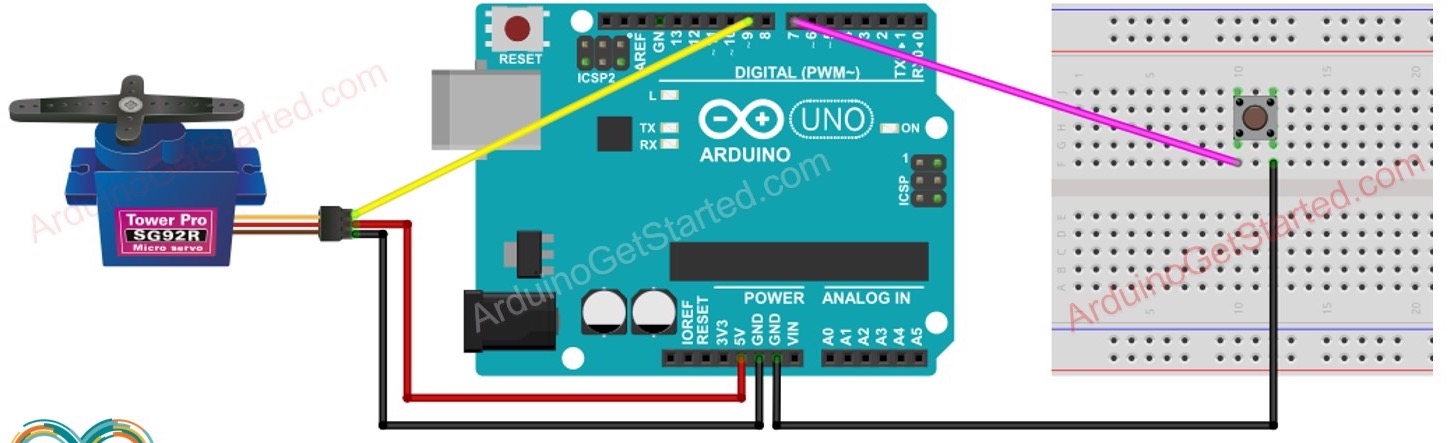
Connect button and servo motor to arduino.For digital module, there are two pins, one goes to numbers, the other one goes to ground; For analog modules, there are three pins, one goes to vcc(5V/3.3v), one goes to GND, one goes to analog pin (numbers with wave.)
The code is below:
Video:
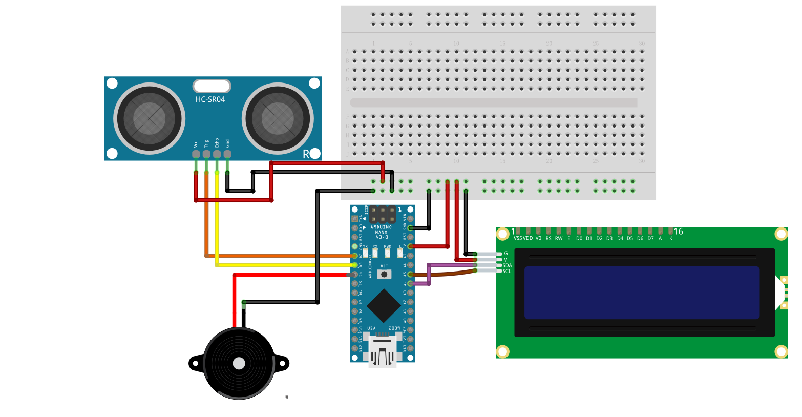
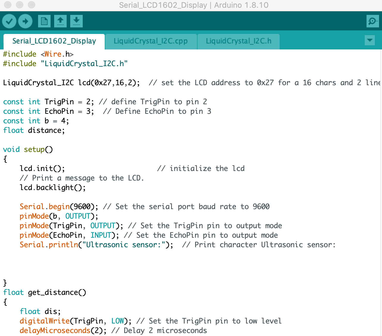
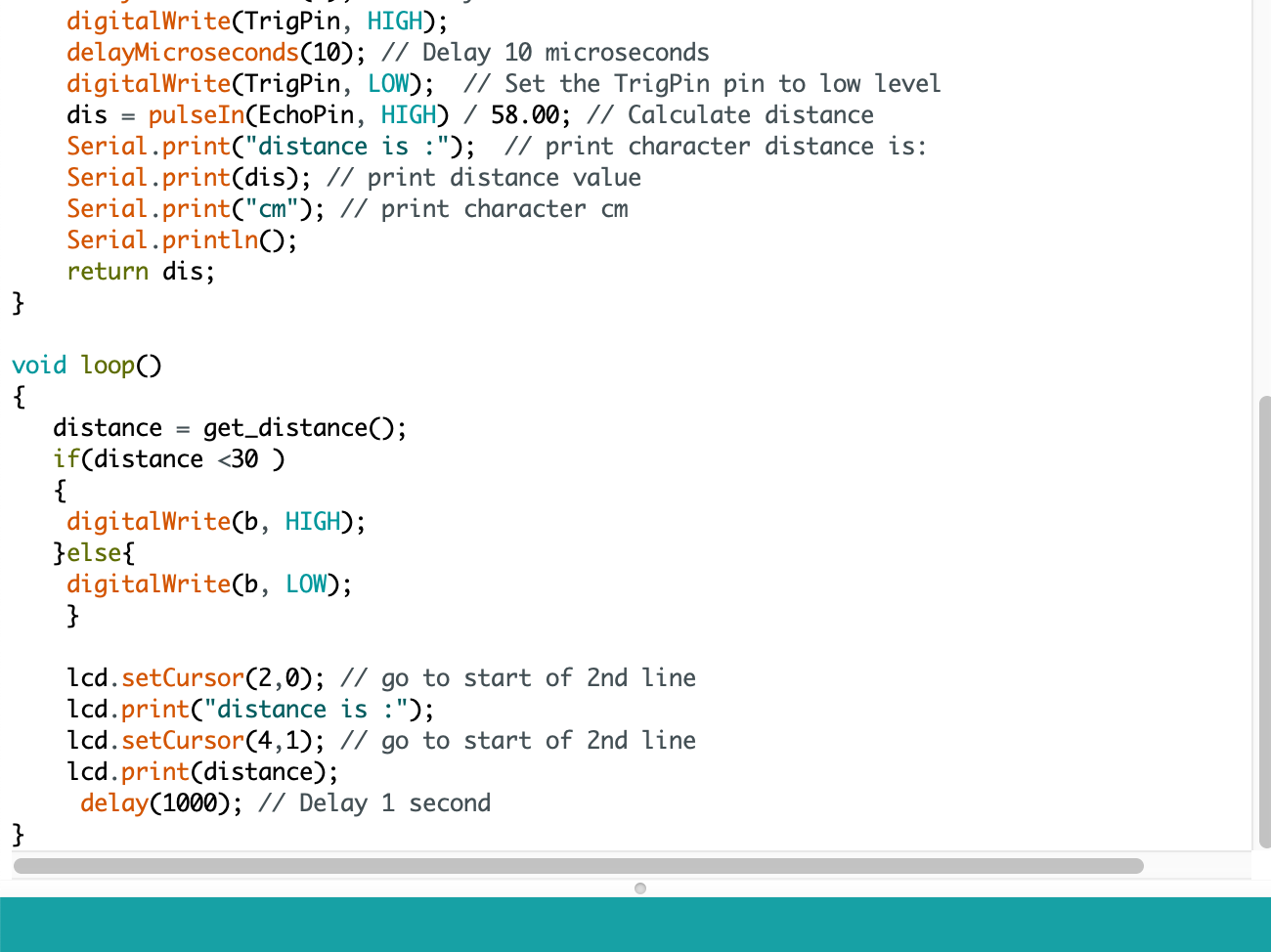
Arduino Nano Radar project:
Programming the Echohello Board

Installing ATtiny support in Arduino using the built-in boards manager.
- Open the preferences dialog in the Arduino software.
- Find the “Additional Boards Manager URLs” field near the bottom of the dialog.
- Paste the following URL into the field (use a comma to separate it from any URLs which has already been added):
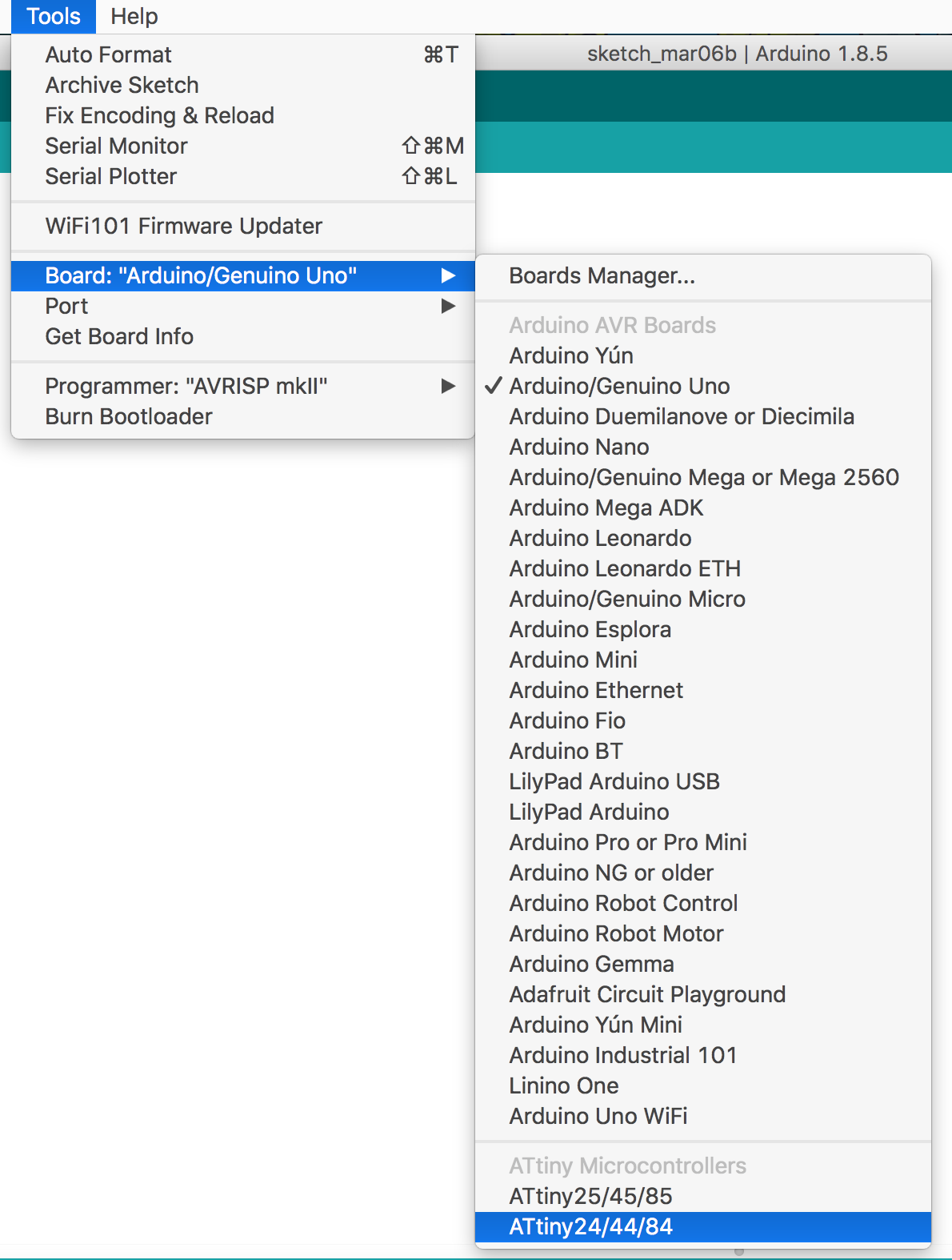
- Select ATTiny22/44/84 from Tools/Boards menu.
- Select ATTiny44 from Tools/Processor menu
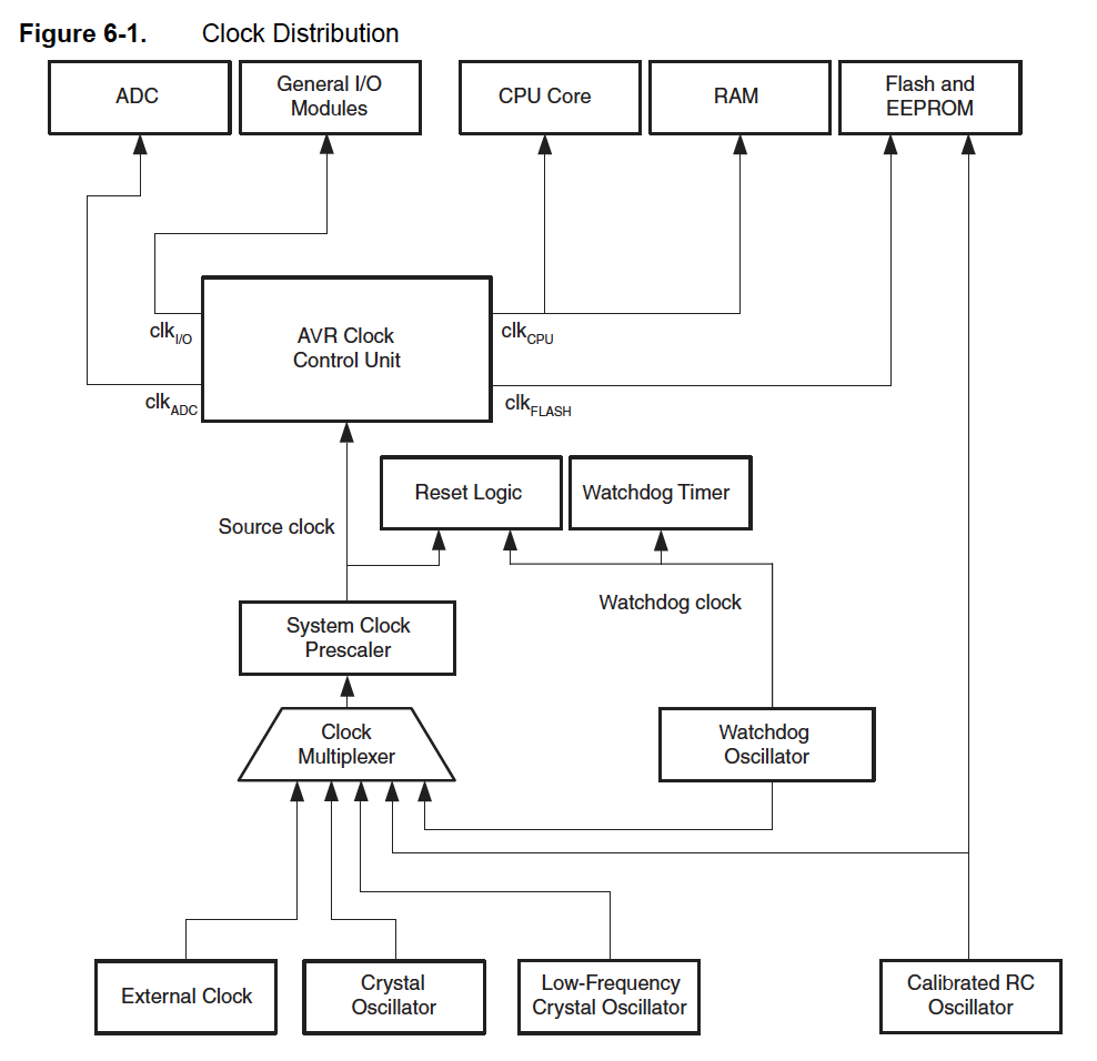
- Selct 20MHz clock (external) from Tools/Clock menu
- Select USBTinyISP from Tools/Programmer
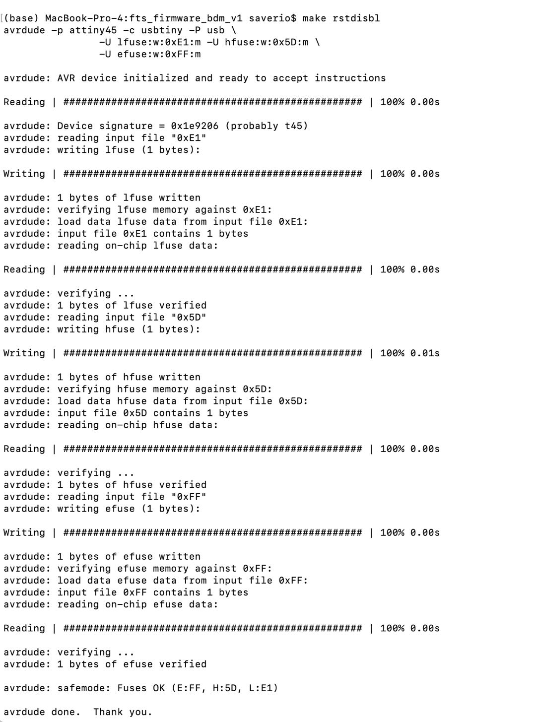
- Then select Tool/Burn Bootloader
After I test my Helloboard, I forgot to take video, and I also can't find my hello board later, so I will use my final project GINO board for this week's assignement.
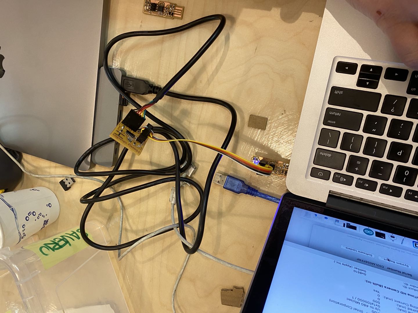
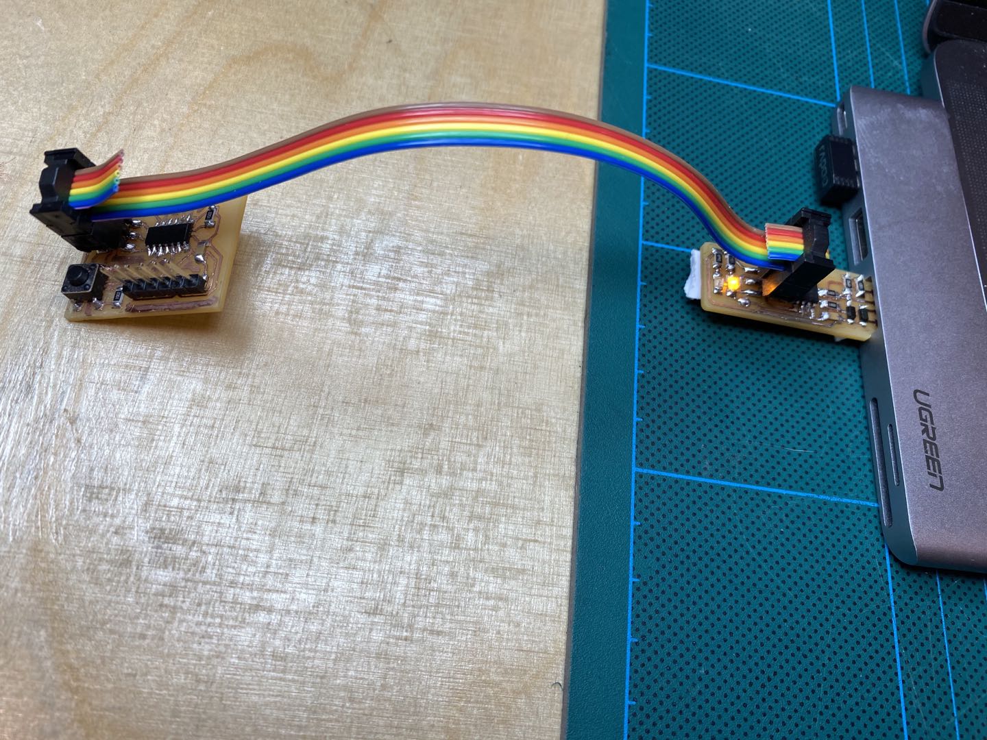
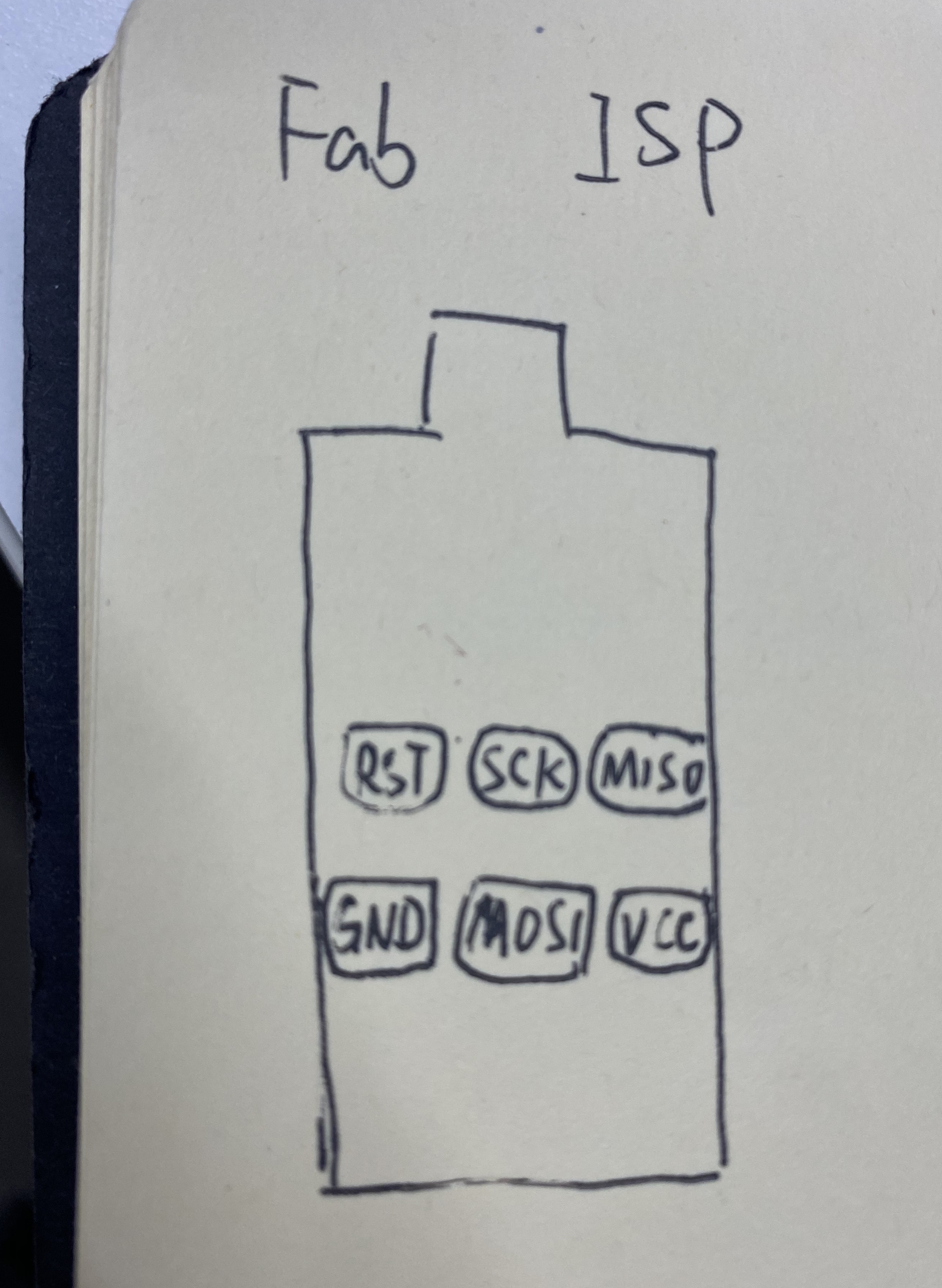
Programme in Gino board: connect Fab ISP with GINO board.
FabISP layout, just to remember the pins, I also write it on my notebook.
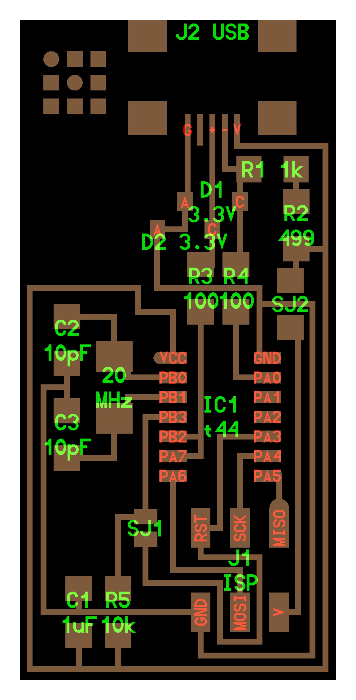
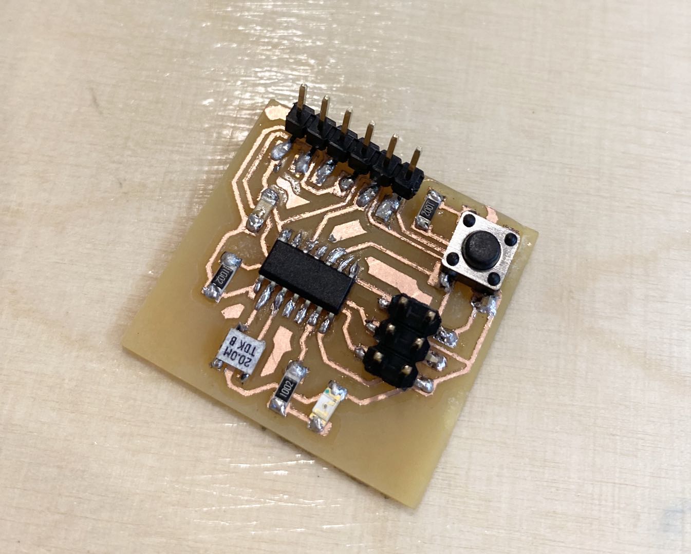
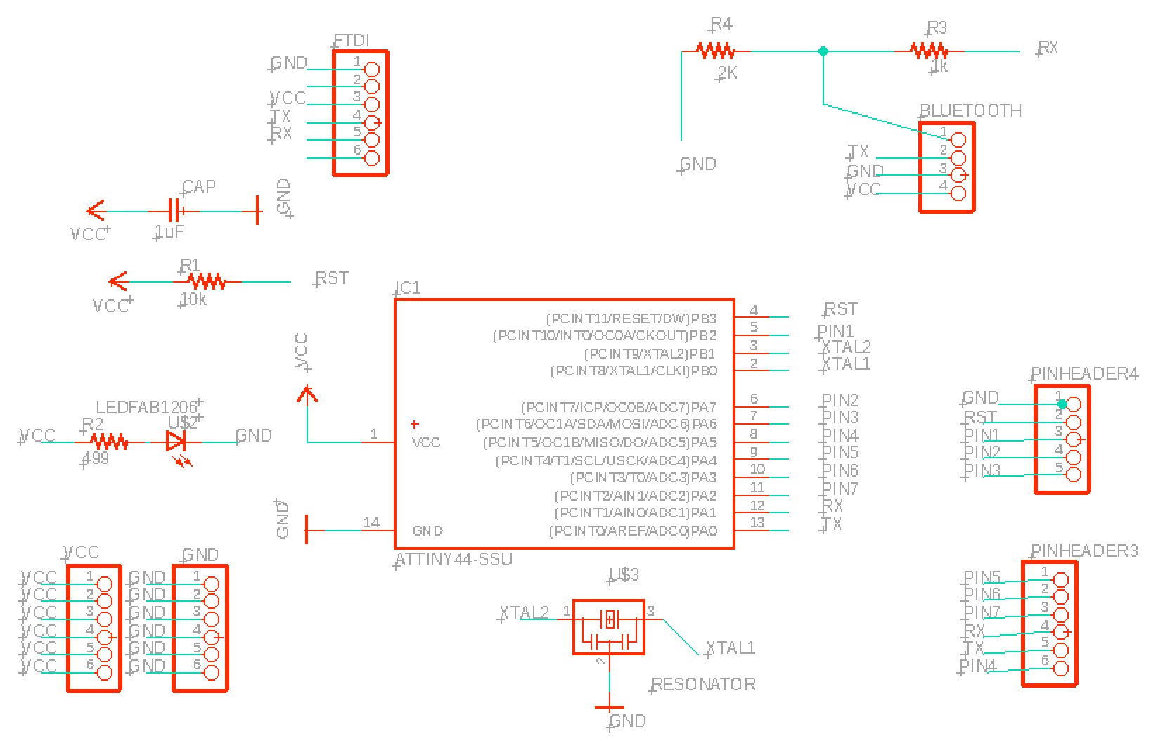
Gino board layout:
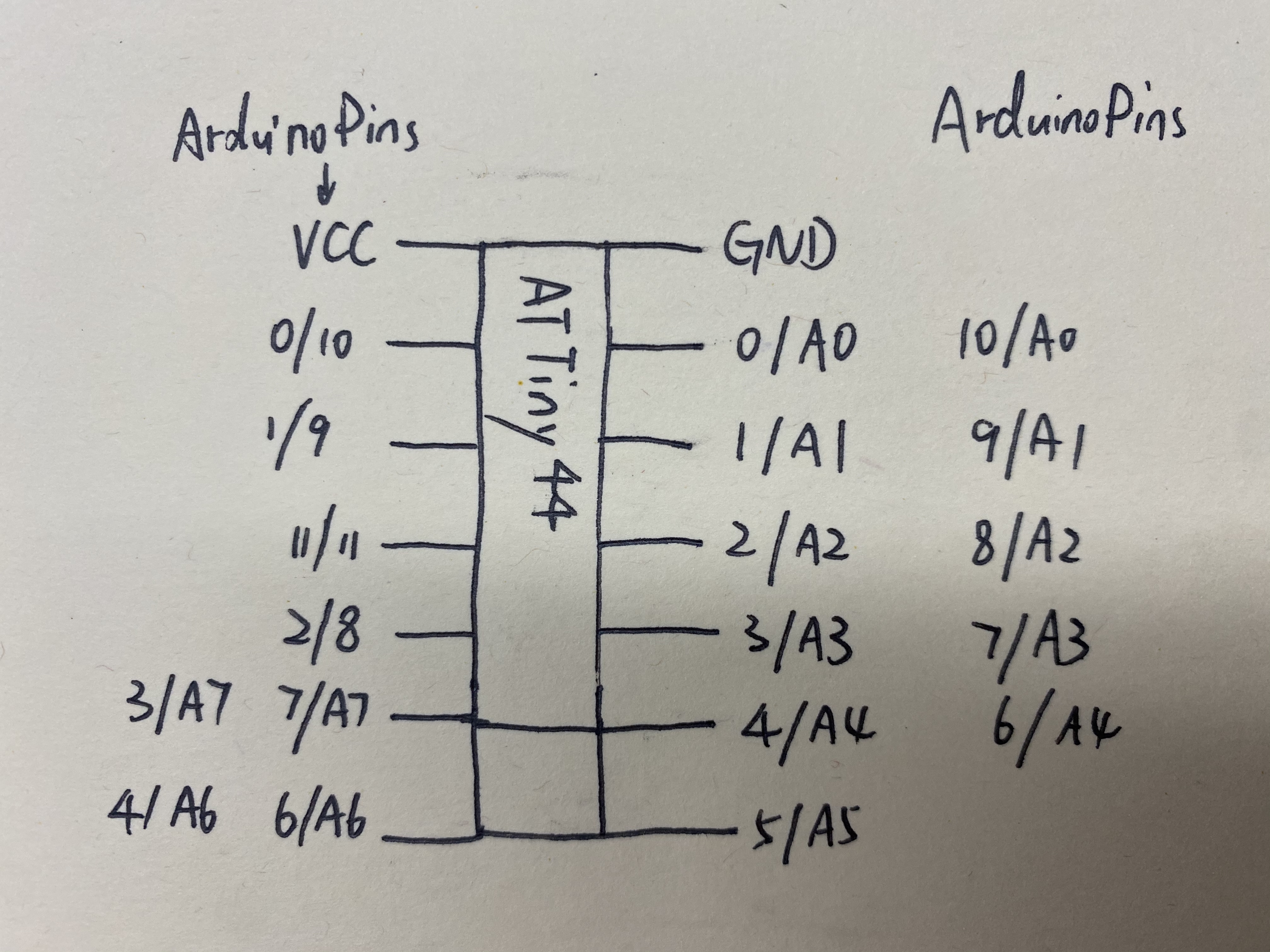
Attiny 44 Pin out: I need to use Aduino IDE to compile the attiny, so I need to figure out attiny44 pinout in arduino.
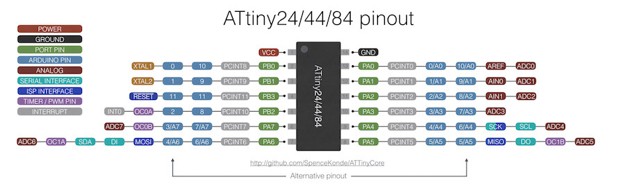
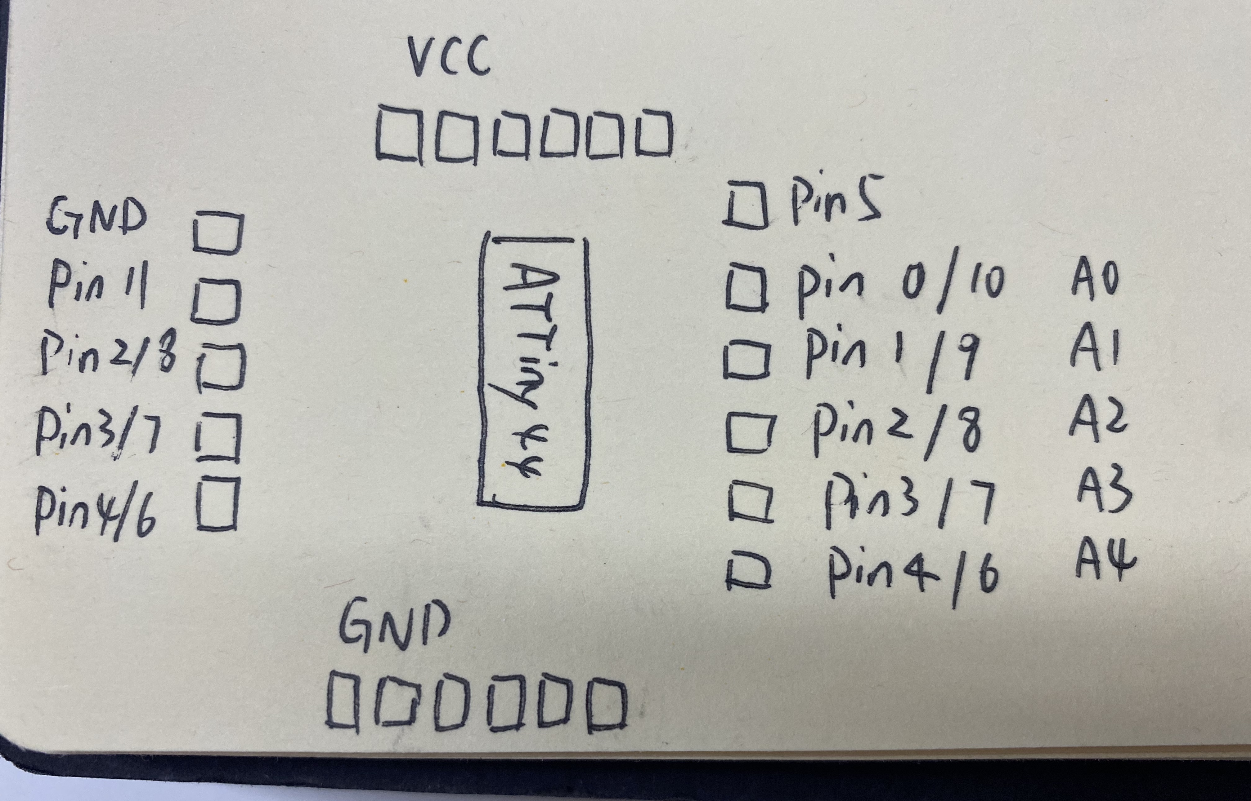
Attiny 44 pinout in arduino.
Gino board Pinout in Arduino
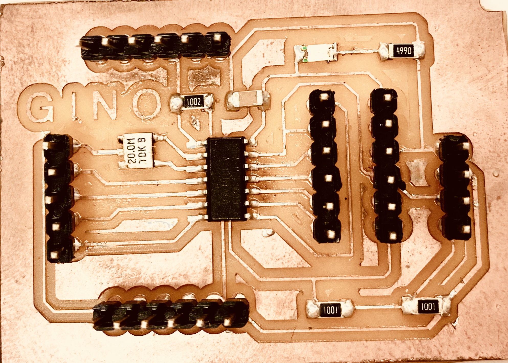
Check Gino board
I haven't use GINO board for a while, when I connect it with a LED it doesn't work at first. I use multimeter to check the connect first, then I also try to connect it with different pins, then I realize pin 2 is stop working, so I use other pins.
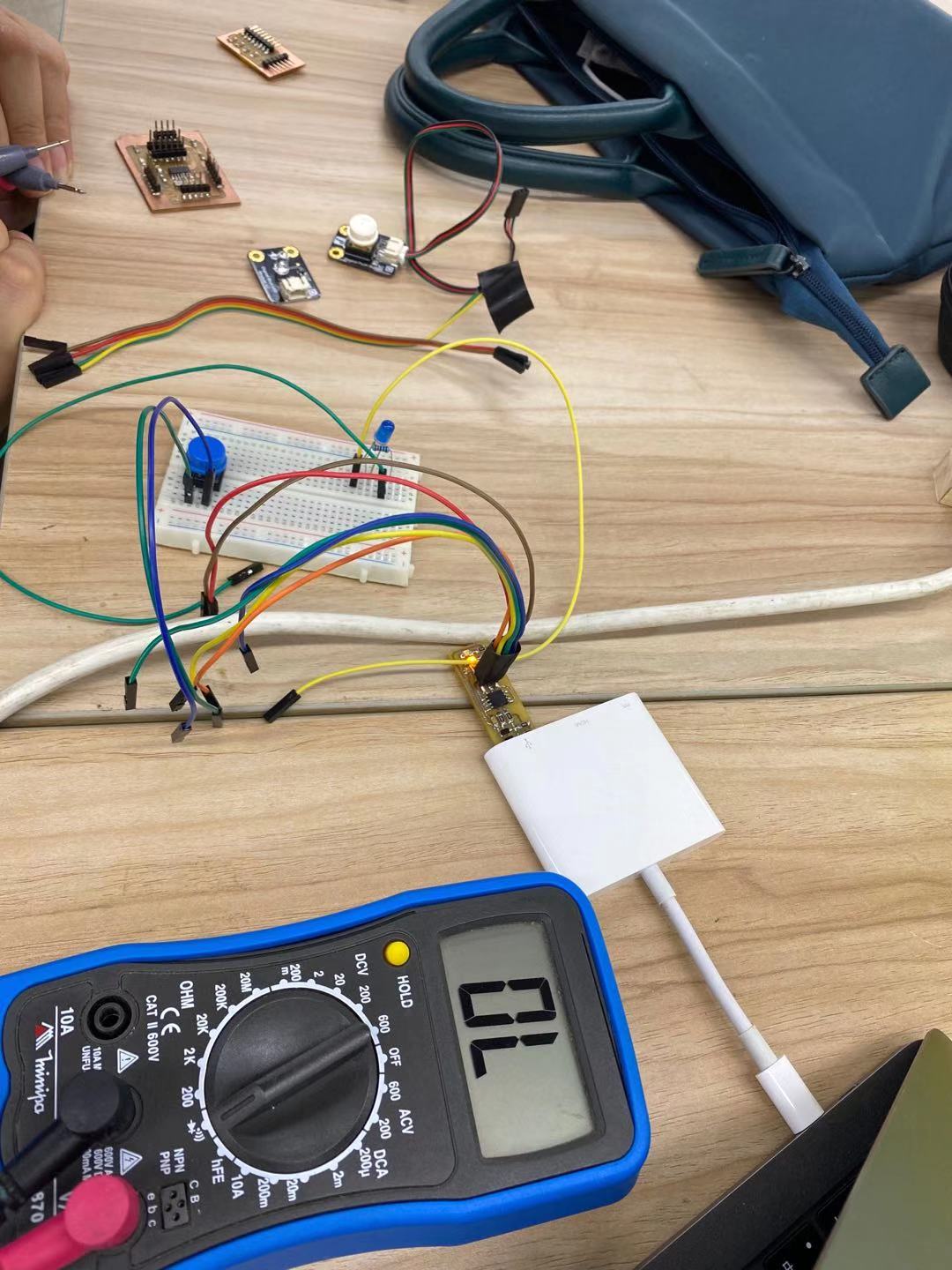
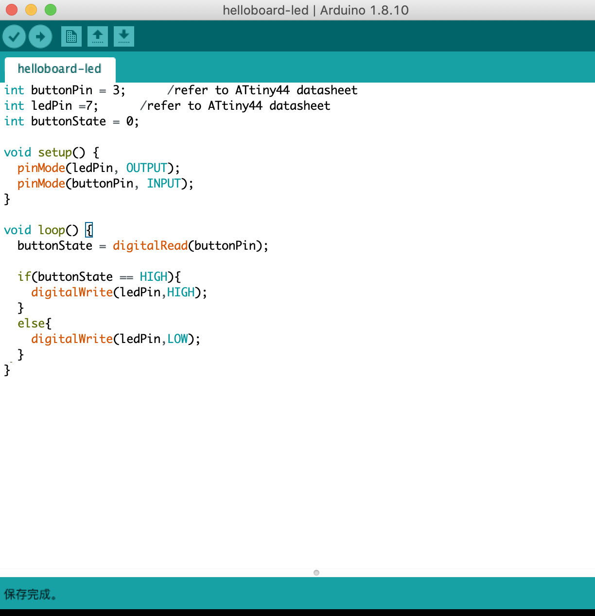
I use a touch sensor as input and led as output:
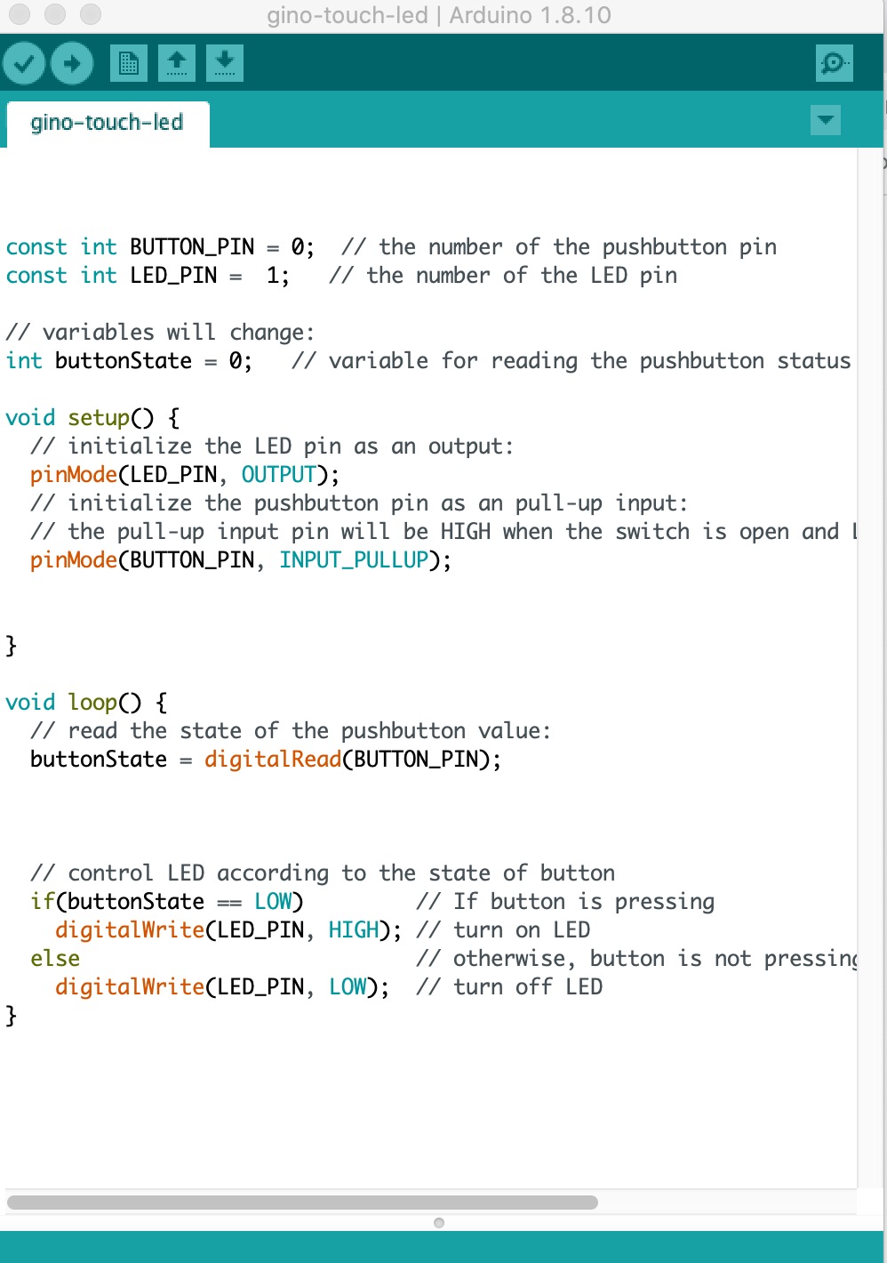
It's working well.
Download Link:
- Download code Fade led.
- Download code Nano Radar
- Download code Button control servomotor
- Download code Gino-touch-led.