Week 4_ ELECTRONICS PRODUCION
For the group project we used the milling machine with two different direction settings: climb and conventional.
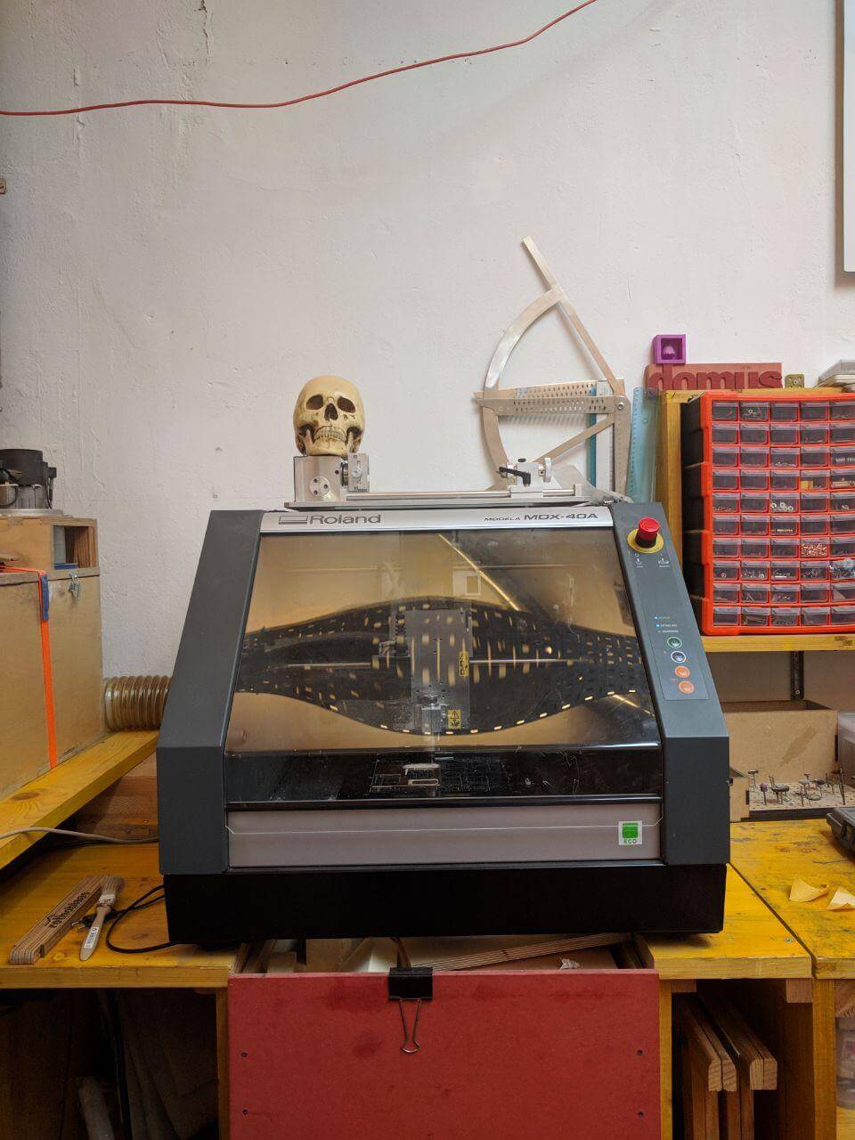
The milling cutter in our lab is a Roland MDX-40A cnc router.
PCB fabrication
In order to design the PCB there have been several preparation moments.
I choose a Fab Tiny board to make this assignment.
Step by step:
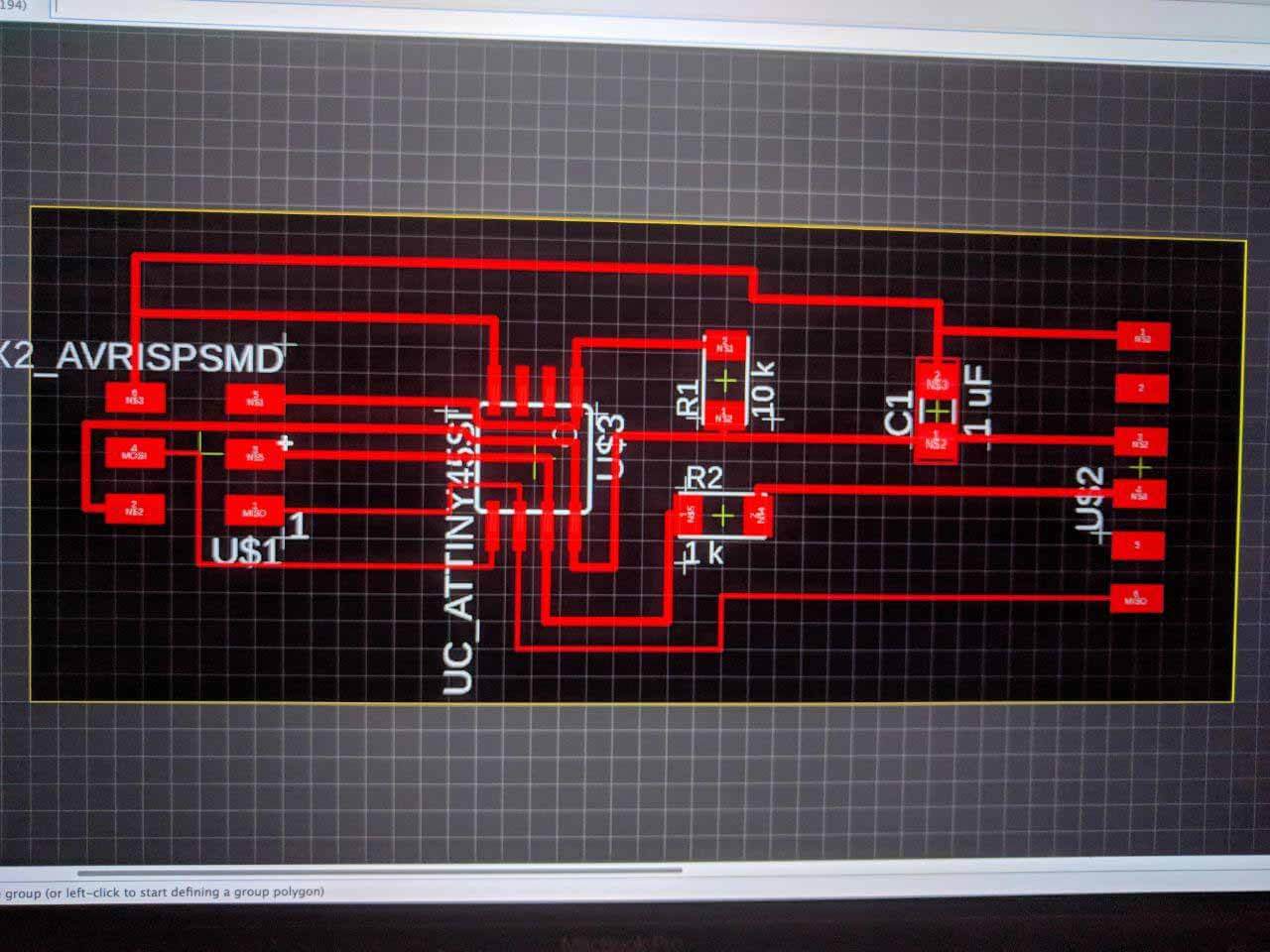
- I did the schematics by Eagle.
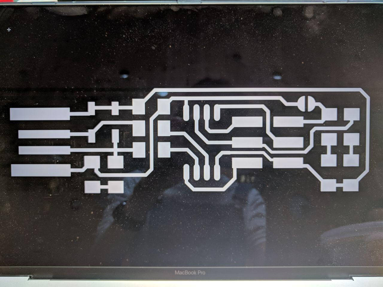
- I did a PNG with the drawing of the circuits.
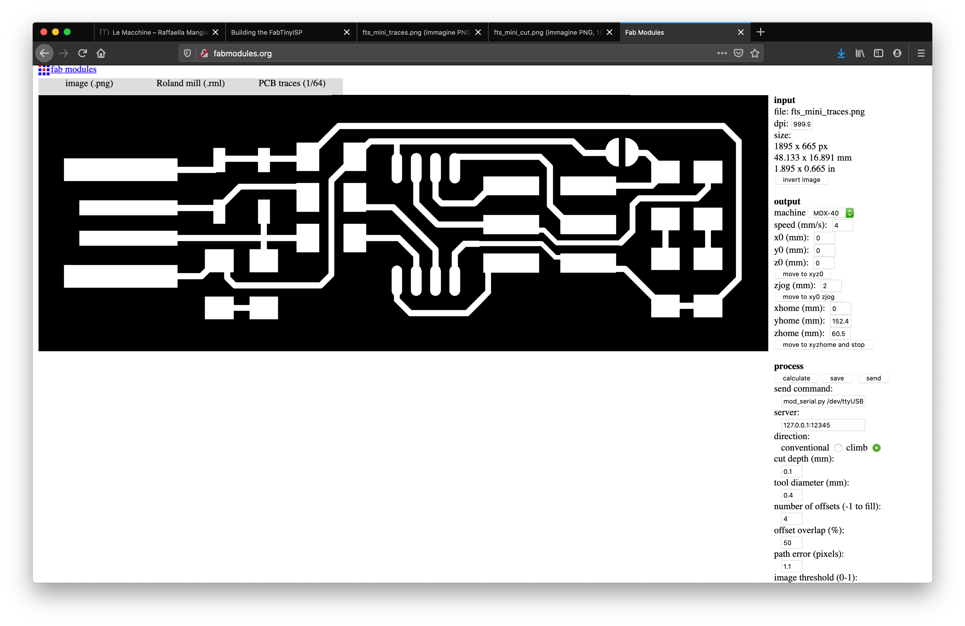
- I exported it by FabModules.
Milling machine XYZ origin setting
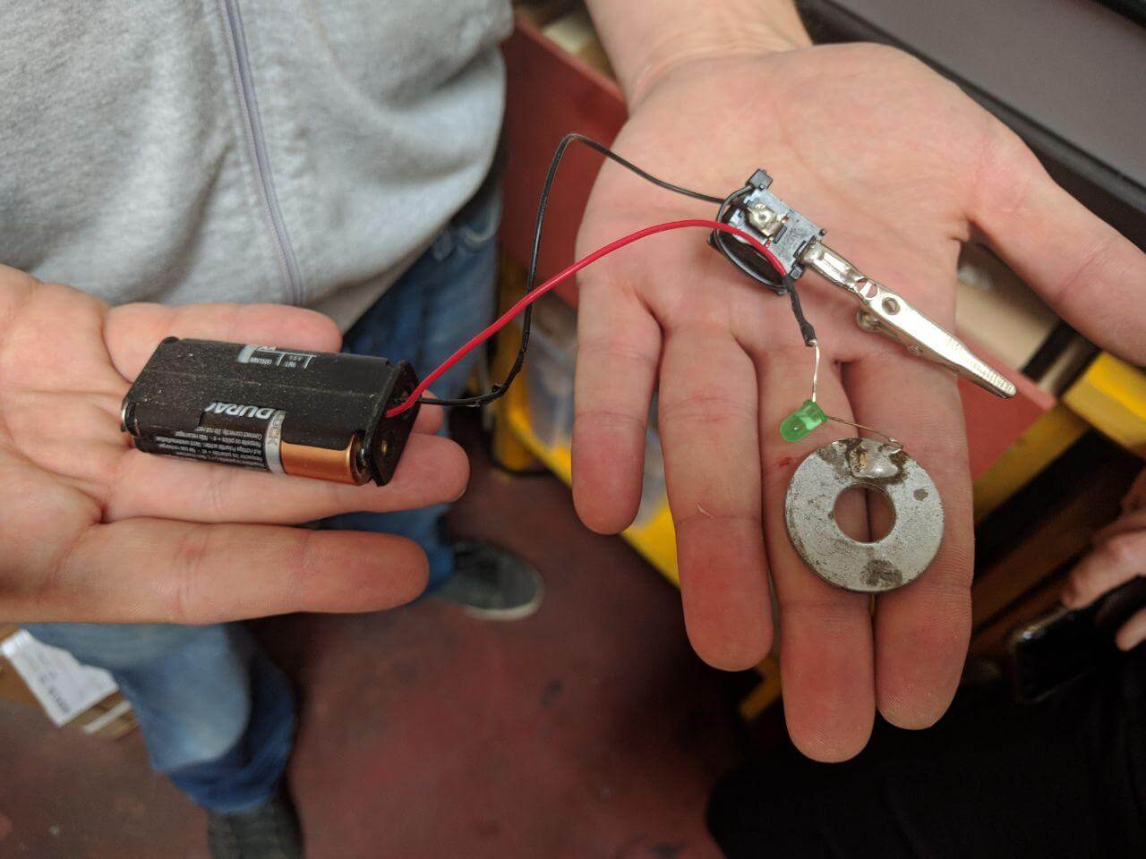
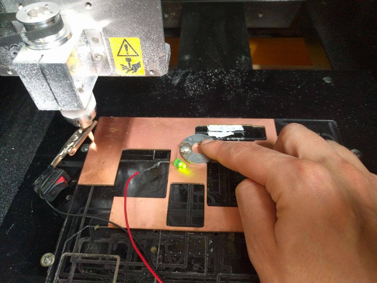
I prepared the machine and regulated the level of the cutting element on the copper surface using this DIY tool: when the LED lights on means the level is right to set the Z origin of the milling machine.
PCB milling
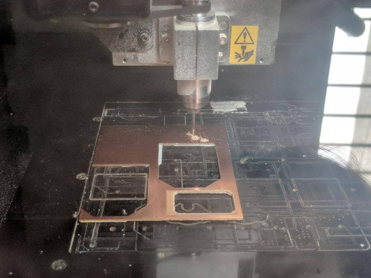
After turning it on, I moved with the head machine of the machine with its software over the area I desired to start milling, but before pursuing in this operation I had to zero the coordinates and adjust the height of the mill.- I milled the PCB with the Roland MDX-40A. I prepared the milling machine taping carefully the PCB board and chacking it was well standing on the milling surface.
I turned the machine on, I zeroed the coordinates adjusting the height of the mill, and moved the head of the machine using the arrows on the Roland where I wanted the milling to start.
The two types of manual movement setting on the softwere we use in the lab: continous, for rapid movement across the board and by staps 10/100/1000. The last option is the best for controlled mill positioning.
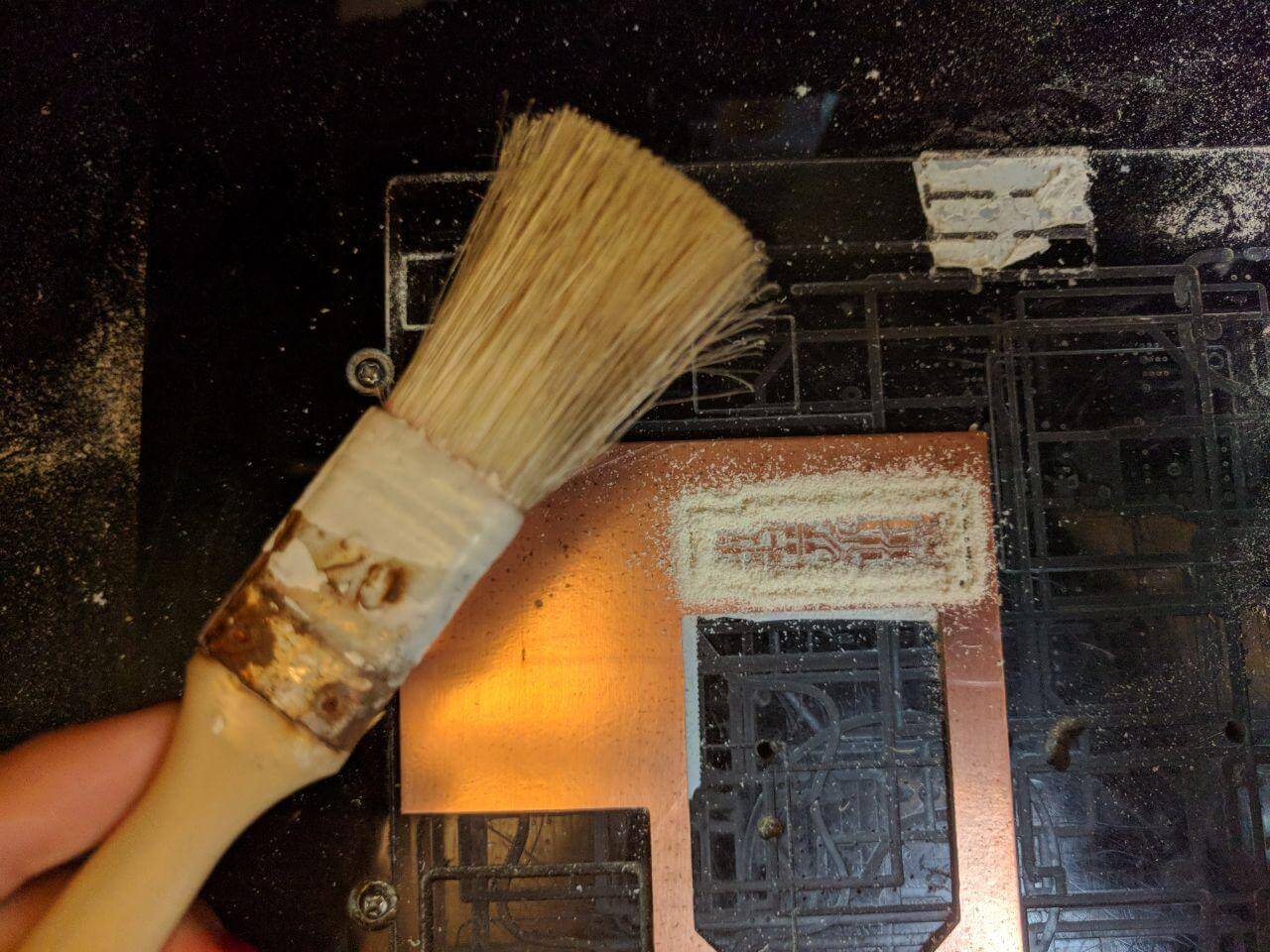
After these steps, set Z command and initiate the milling process using a 1/64 tip. - At the end of this operation, I removed the copper dust on the board surface with a brush.
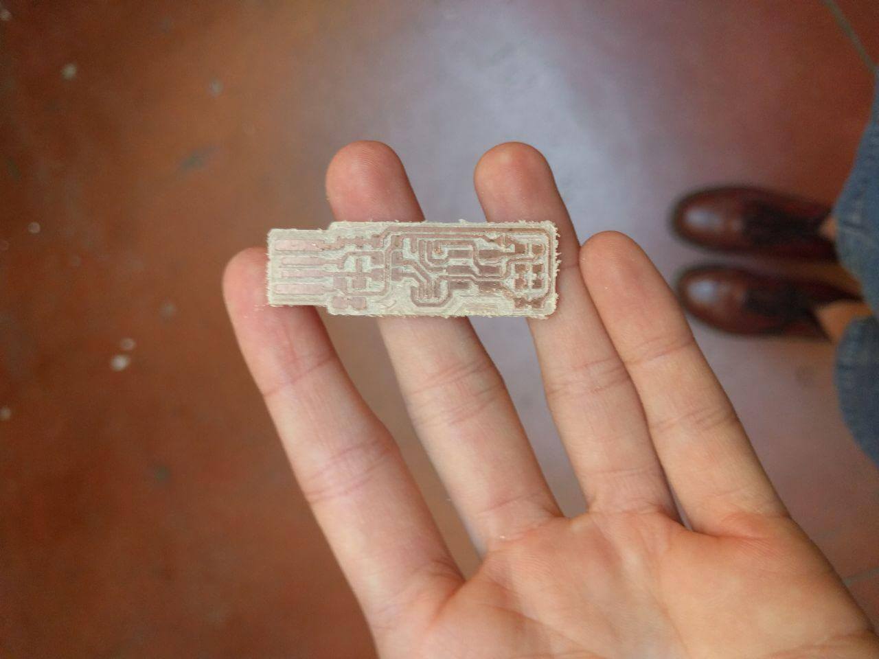
Then I changed the tip to a 1/32 to drill the holes and cut the outline. - I unsticked the piece from the cutting surface and then I cleaned it.
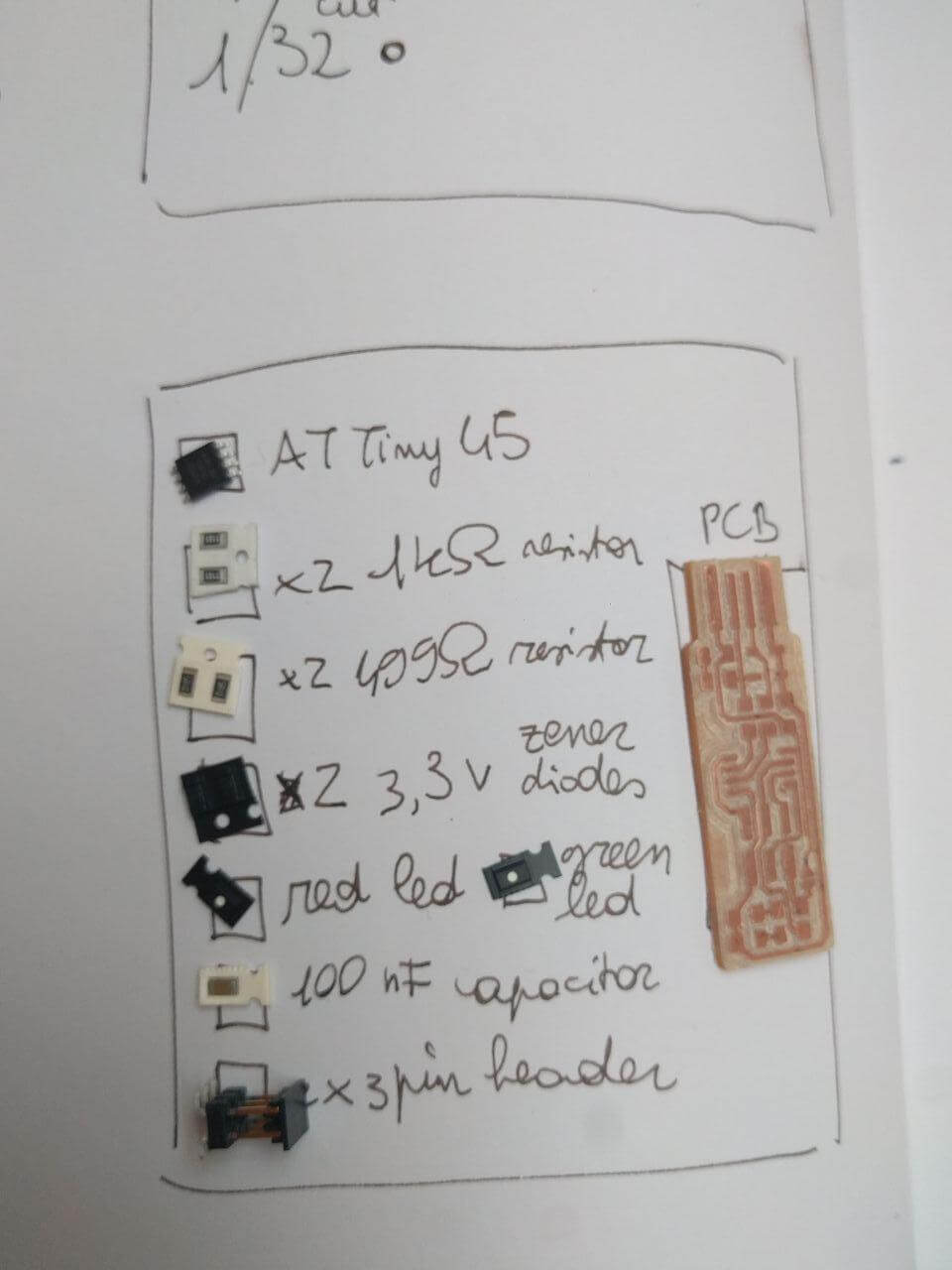
FabTinyISP components addition
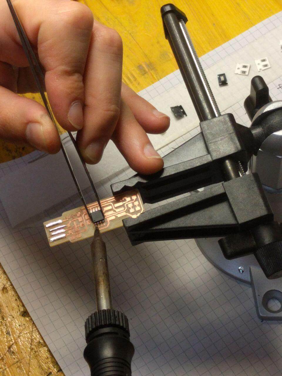
- I sticked the clean PCB to start soldering the components of the bill of components.
- I started soldering for the first time.
- I added the components to the PCB.
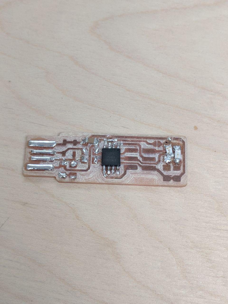
My first try failed, since i positioned the AtTiny in a wrong angulation.
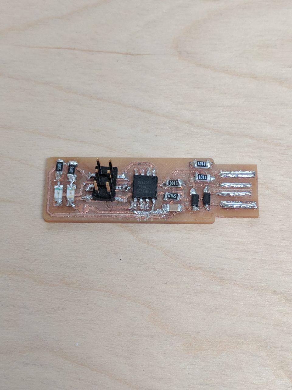
The second time I corrected it and it came out better.
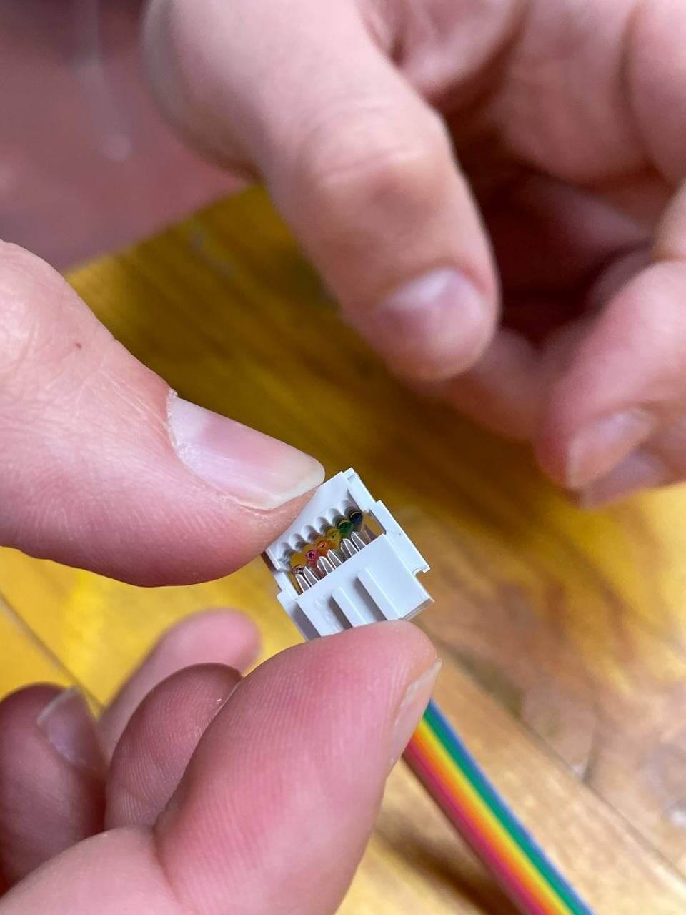
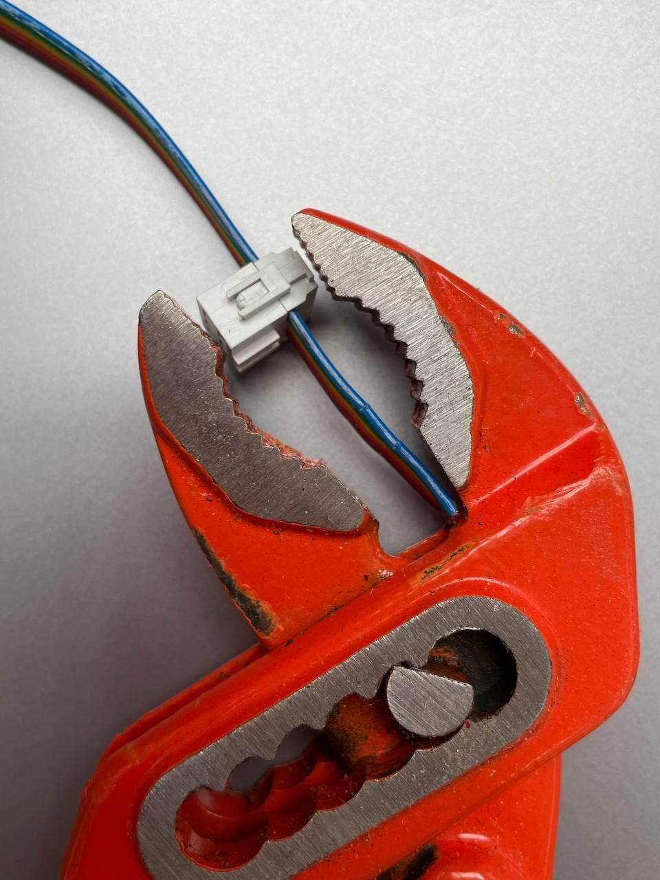
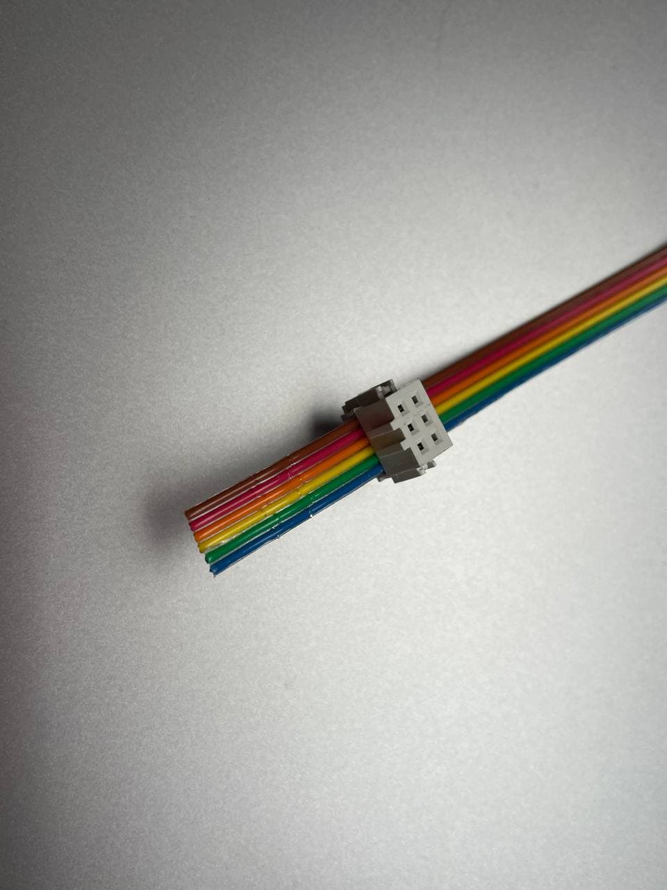
Ribbon ISP fabrication
- The ribbon is a bridge that connects the boards to a programmer or to other boards.
First of all, you have to take only 6 strings and close them with a pincer.