
For the group project, we milled out two line gauges, one using ‘climb’ and one using ‘conventional’ mill direction settings.
At OpenDot, we have a Roland MDX-40A cnc router. It has a working volume of 300x300x100mm and a maximum spindle speed of 8000rpm and a maximum feed rate of 3000mm/min.
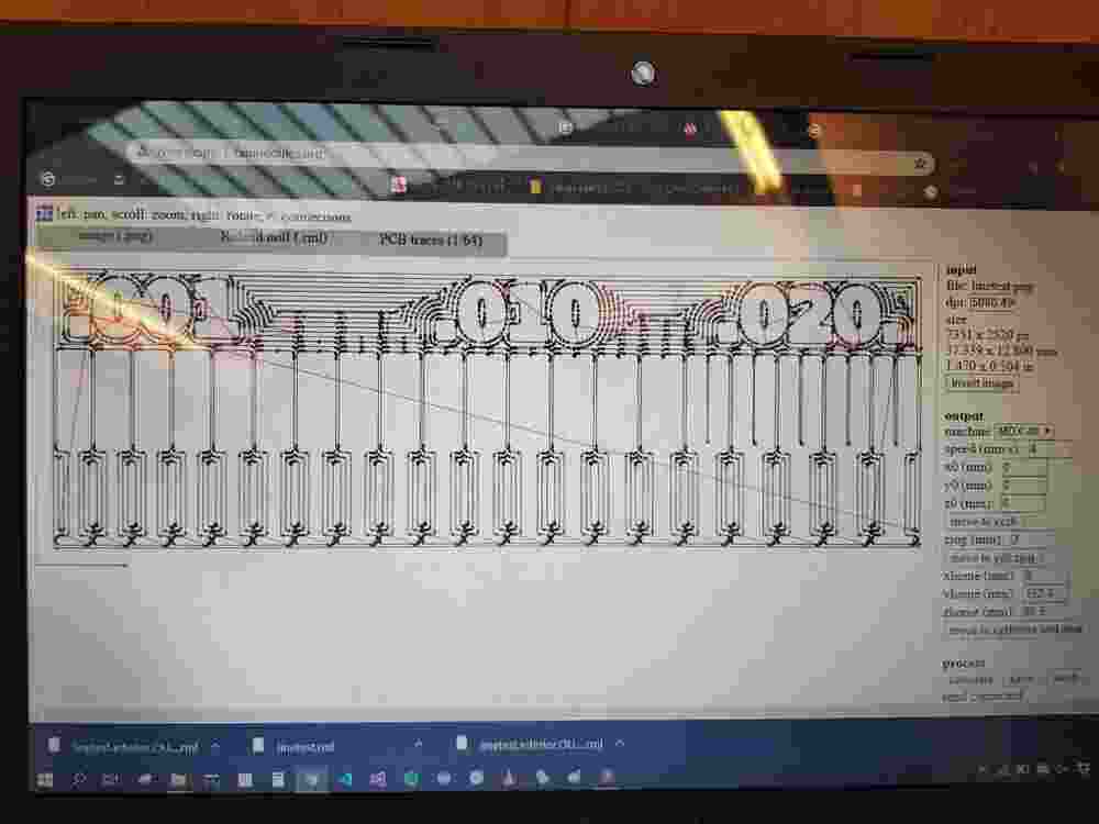
To generate the CAM files, we used the old fab modules, since the new version does not (currently) have builtin support for our mill. The default settings builtin for the MDX-40A are largely perfect, we only zeroed out the origin in the settings.
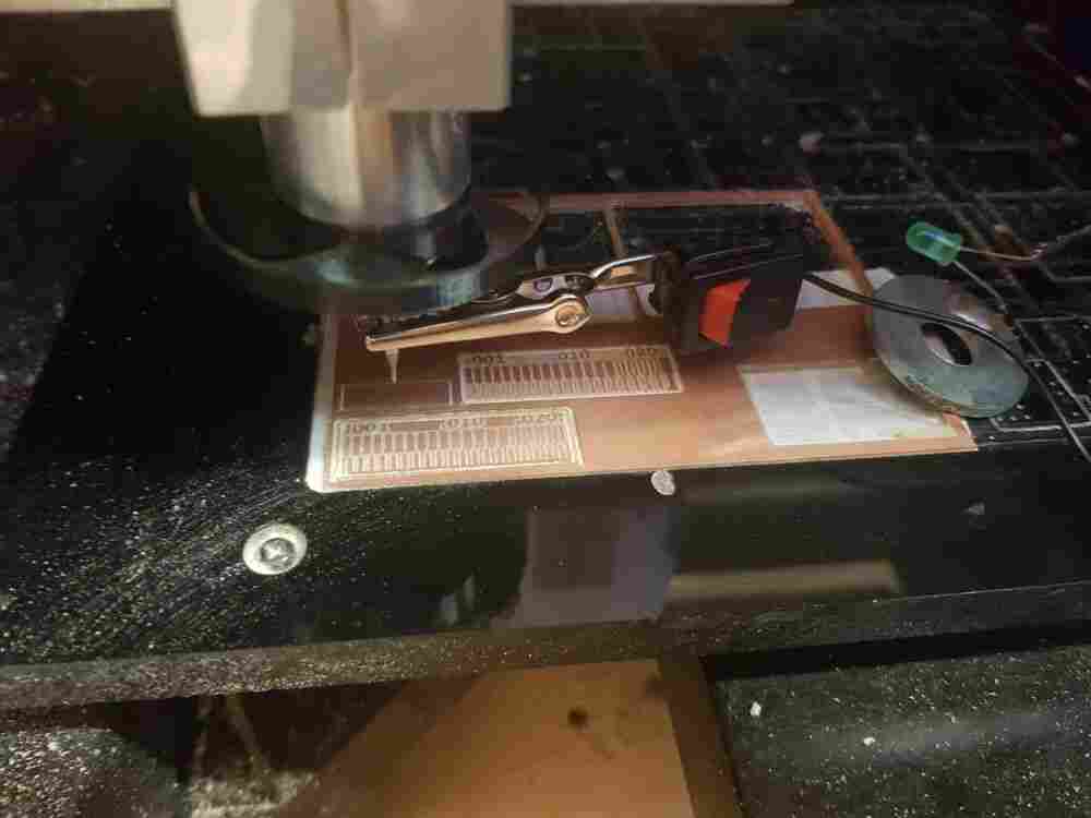
We attached the stock to the sacrificial layer using double-sided sticky tape.
To find the Z origin with respect to the tip of the tool, we use a simple continuity circuit probe a staff member of the lab put together. It is essentially just a battery, a switch, and an LED (with a current-limiting resistor) in line with a crocodile clip and a large steel washer interrupting the circuit. The crocodile clip can be attached to the endmill, while the washer is lightly pressed against the copper stock. This allows to slowly lower the tool until the LED begins lighting up solidly.
We noticed later that some attention needs to be paid to the spot on the copper that the test is performed on when the stock has been milled already, since the spot and the washer need to be electrically connected of course, which may or may not be the case if the board already has been (partially) cut.
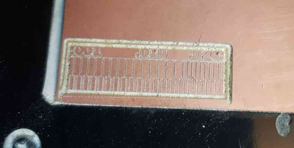
Here is the board after the trace pass with four outlines:
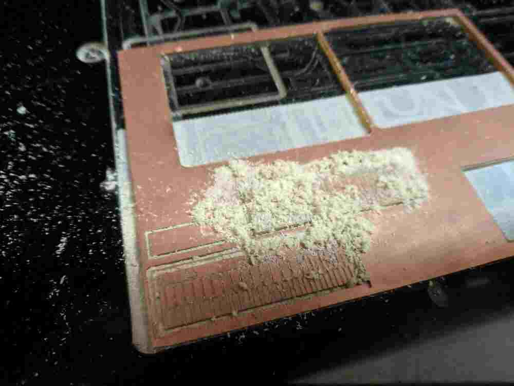
Immediately after cutting, there are a lot of particles that have to be manually removed with a brush:
Since the trace-pass went smoothly and with no problems, we switched to a larger endmill and proceeded with the outline. As others before us, here we faced some issues with Neil’s line gauge files; the outline file has a small transparent artifact at the bottom that causes the fab modules not to route out the lower edge of the board.
We fixed this initially by inverting the image, which moves the outline cut deeper into the board by two tool radii. In retrospect we should really have investigated the issue more and fixed the outline file manually, since this way the line gauges are cropped at the edges and the numbers are slighltly harder to read.
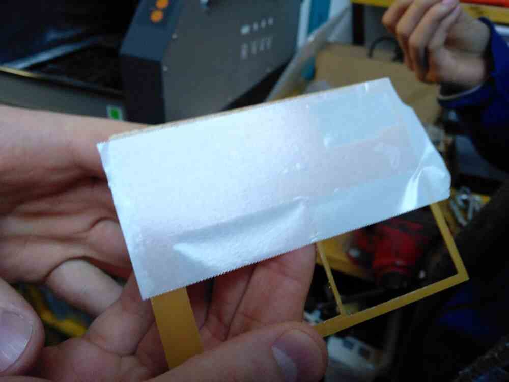
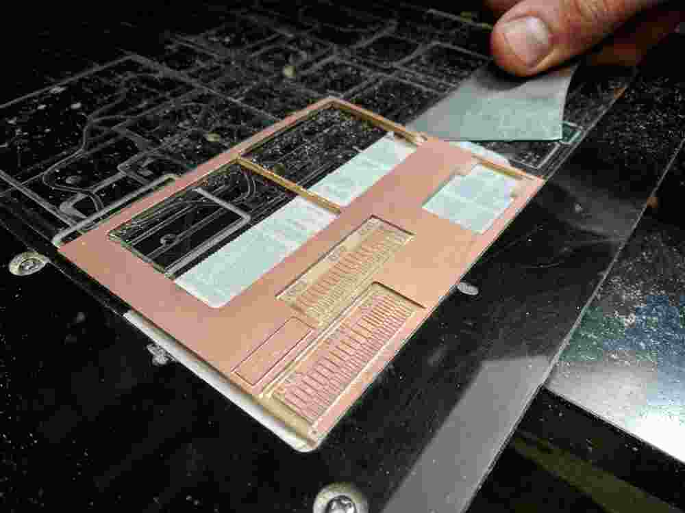
To remove the board, we have various cutting and prying tools, that need to be used to carefully pry off the board without bending neither the remaining stock nor the fabbed board too much.
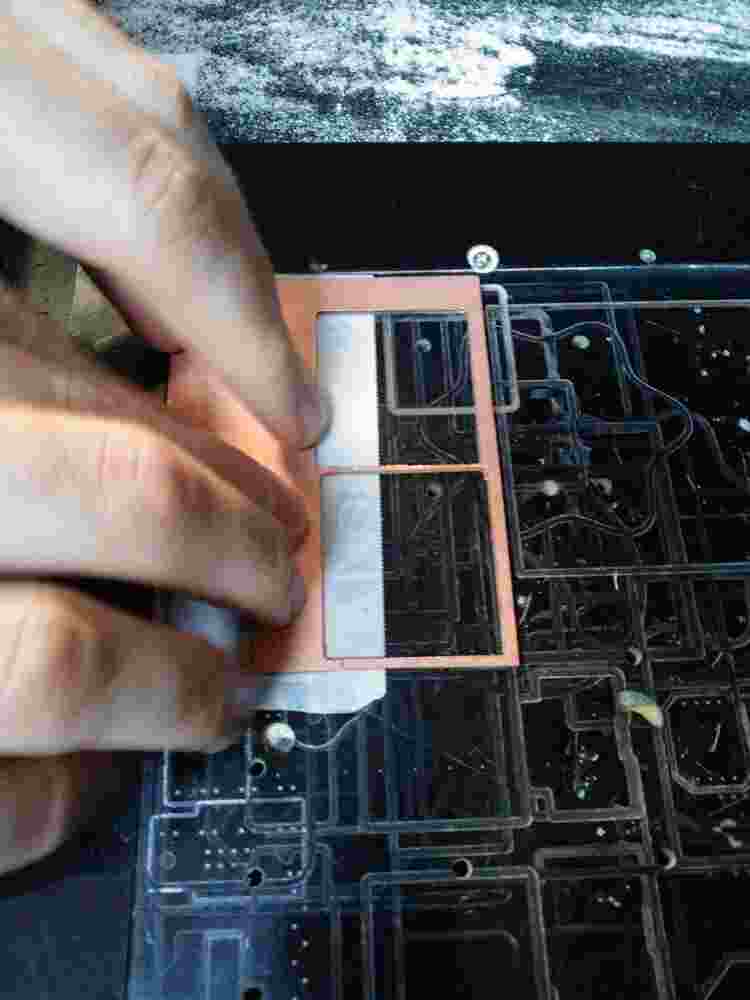
On the second gauge (pictured on top in the following image) we used the conventional cut direction and set the number of outlines to -1 in order to completely remove all excess copper. Here are both pictured together:
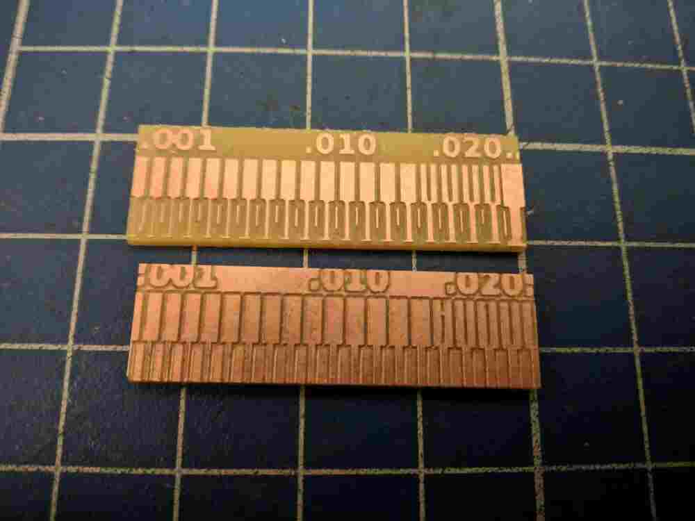
As we can see, we can comfortably mill material down to about 0.003 trace width, while the track spacing has to be at least 0.016 for these settings.