Project
Final Project
Assembling
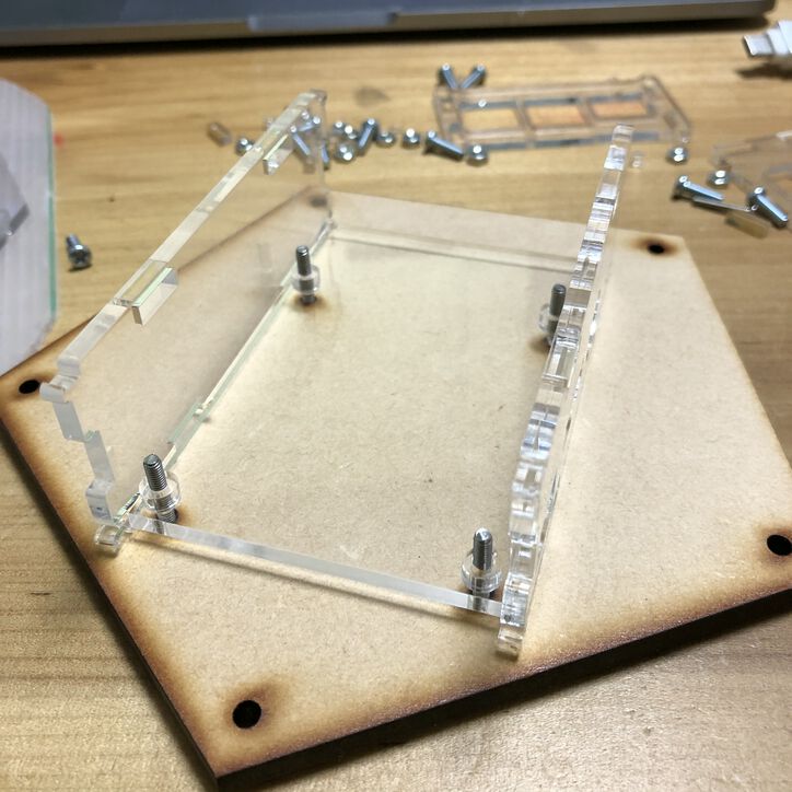
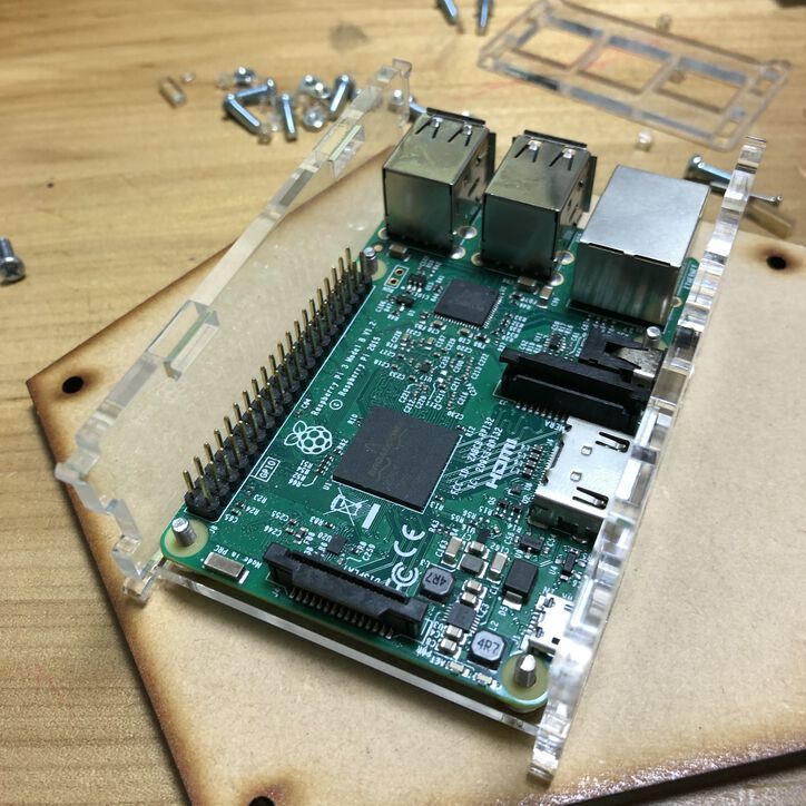
Assembling Raspberry Pi case
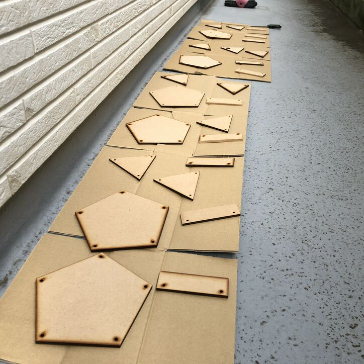
I made laser cut acrylic boards into RaspPi case fixing to the bottom of Pot.
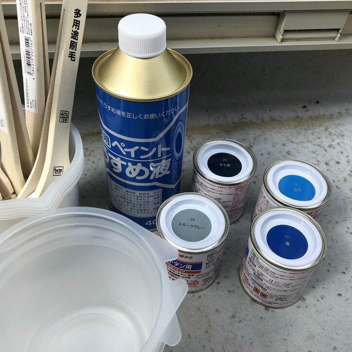
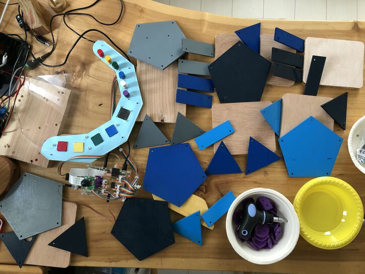
Painting
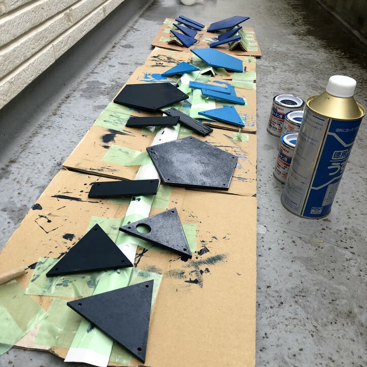
I used lacquer composition of paint to coloring Pot body in 4 colors - sky blue(空色), blue(青), eggplant blue(なす紺) and gray(灰色).
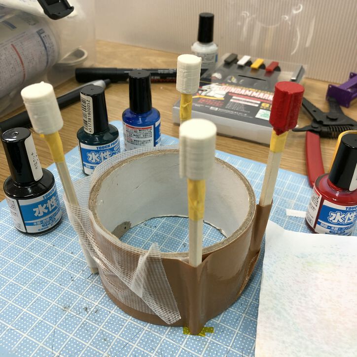
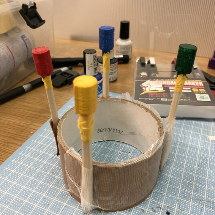
I painted the 3D printed covers of knob on potentiometers. Fortunately, the color is quite similar with the color for tact cover switches.
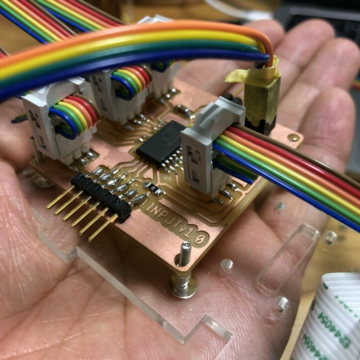
Cabling and assembling
I made cables that fits with distribution of parts in PoTone.
Also I made cables for UPDI and Serial interface boards.
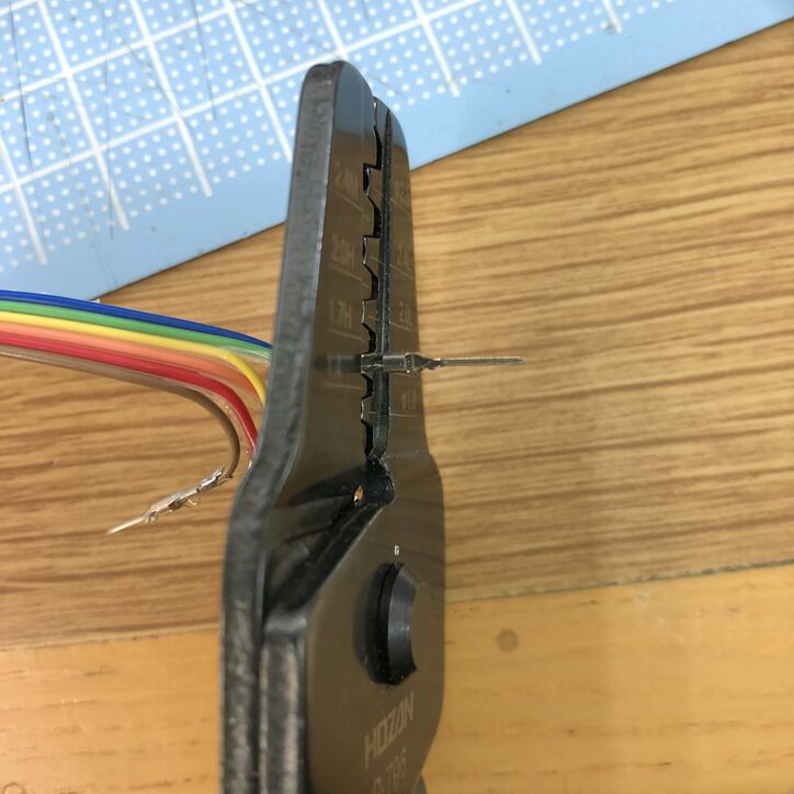
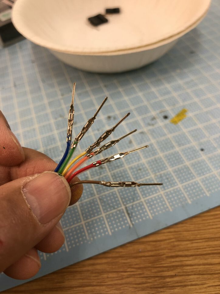
Made 2 pins male/female cable and 6 pins male/female cable.
I assembled a Pot by 3mm screw x 74, 2.6mm screw x 8 (for fixing Raspberry Pi) and 2mm screw x 12 (8 for fixing camera and stand and 4 for fixing OLED),
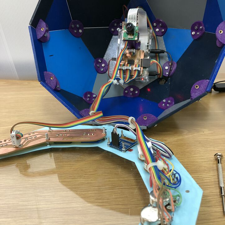
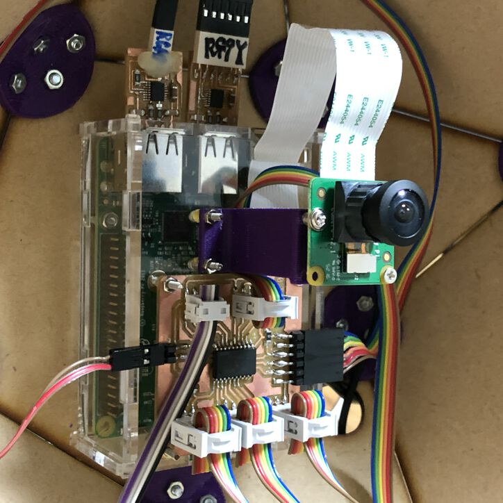
Connected In-out board, switches board and Raspberry Pi.
I also used binders to settle tangling cables to fixed points.