
Electronics Design
Group Assignment
- Use the test equipment in your lab to observe the operation of a microcontroller circuit board (in minimum, check operating voltage on the board with multimeter or voltmeter and use oscilloscope to check noise of operating voltage and interpret a data signal)
Test Equipment at Fablab Kannai
Multimeter OscilloscopeMultimeter
I used TDX200 and tested my echo board.
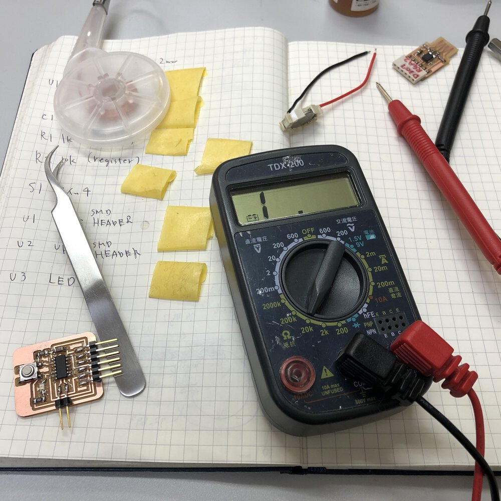
test voltage
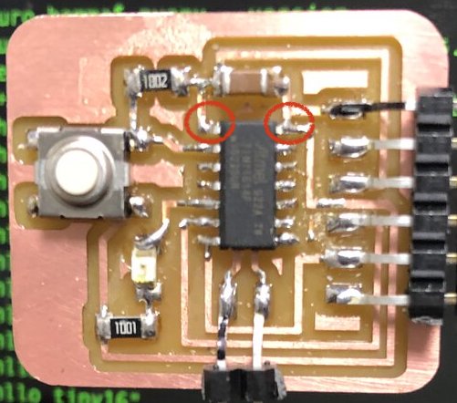
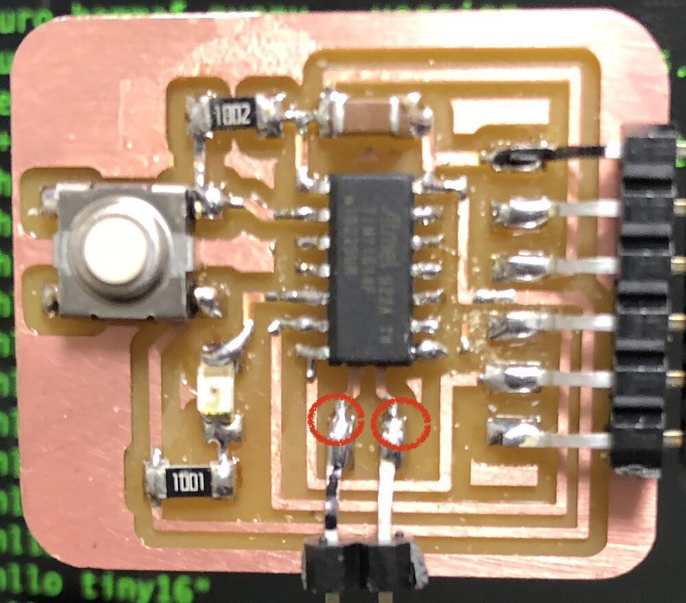
test continuity
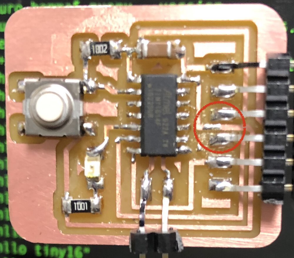
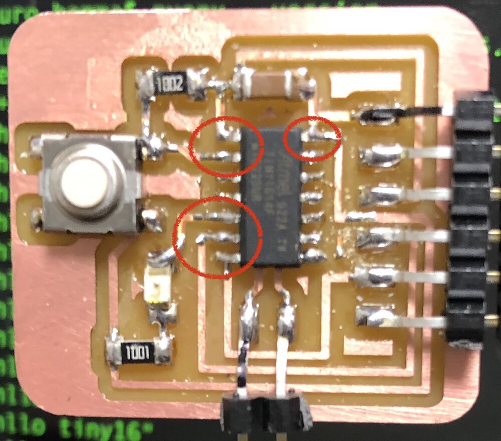
- It's difficult to check tiny parts with tester. I had an error in my operation and found incorrect continuity in failure. Watching carefully the footprint and check gently on the stable table:)
- It's good to use multimeter that can make noise when the machine finds something. TDX200 cannot do that while Sanwa PM3 can do.
Oscilloscope
I used Tektronix TBS1052B and tested my echo board.
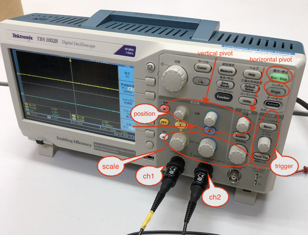
- capture electrical wave in 2ch
- horizontal pivot (time) and vertical pivot (value like voltage, current etc.)
- scaling up/down and positioning
- single mode: capture one time change in the sequence
- auto trigger or manual trigger.
testing voltage

checking 3.2V of voltage when turning switch on the sample board with setting the unit of scale=1V.
testing blink board
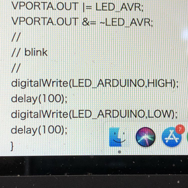
I soldered the leg of register as an extension of pin for controlling LED and checked how that pin works electrically.
the program blinks the led on and off every 200 mill seconds.
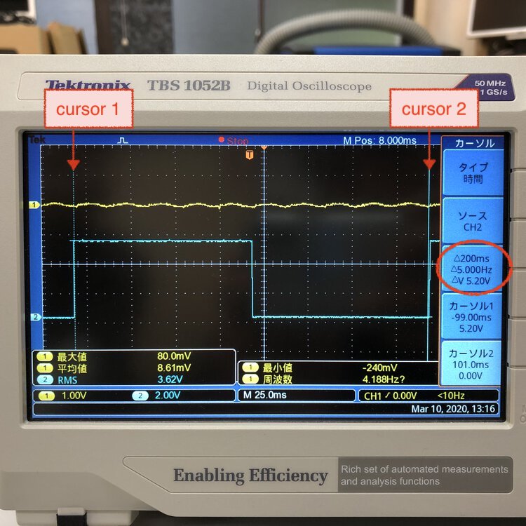
Setting cursor 1 to the starting point to blink on and cursor 2 to the end of blink off.
As programmed, the blink works every 200 milliseconds and the frequency (1 / 0.2 seconds) = 5.000Hz.
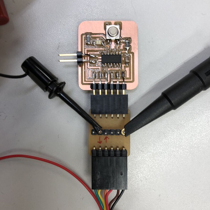
testing echo board
Af first, I had some errors that connect to the probe to inappropriate places.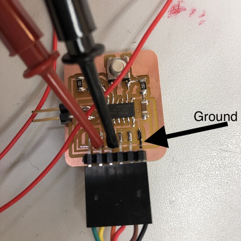 connect ch1 probe to RX and ch2 probe to TX of FTDI, but did not connect the ground.
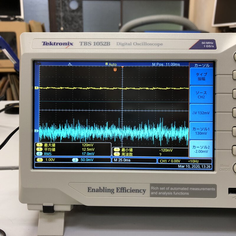 the wave is blurred when ground of probe is not connected.
 I could not find the reason why the wave shapes like this when testing echo.
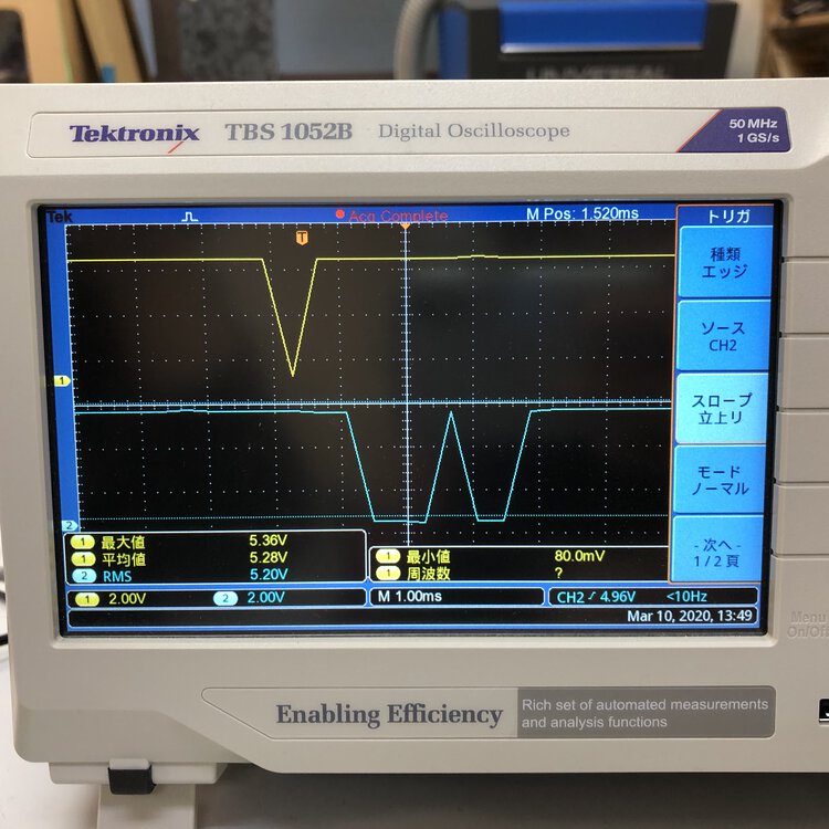
Then I connected the ground of oscilloscope and started to adjust the displayed wave.
Ch1(red): TXD of FTDI (RX of ATtiny1614)
Ch2(black): RXD of FTDI(TX of ATtiny1614)
It's difficult to capture the instant signal in real-time window. So, I used "trigger" function. and got "single" image.
- Type: edge
- Slope: falling
- mode: normal
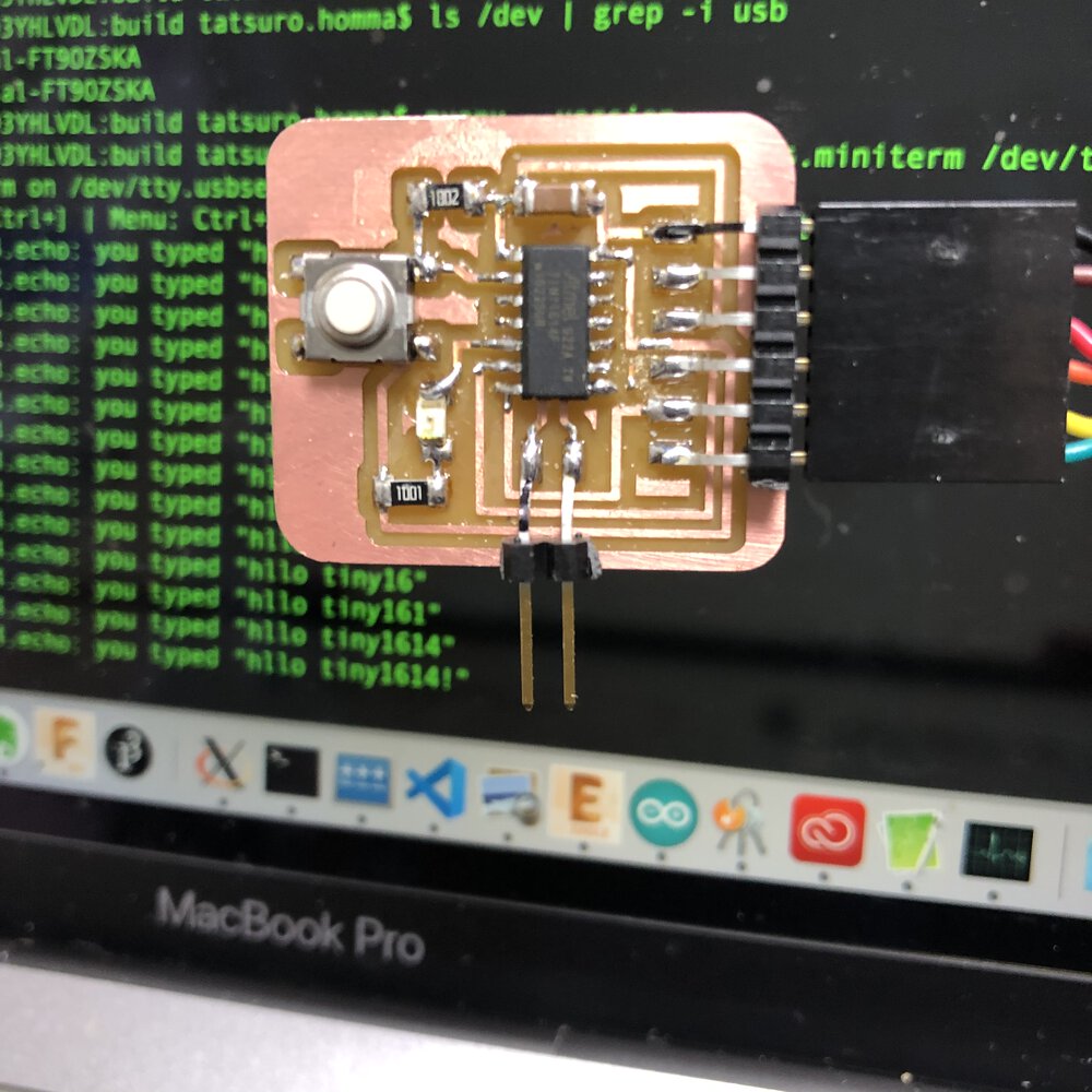
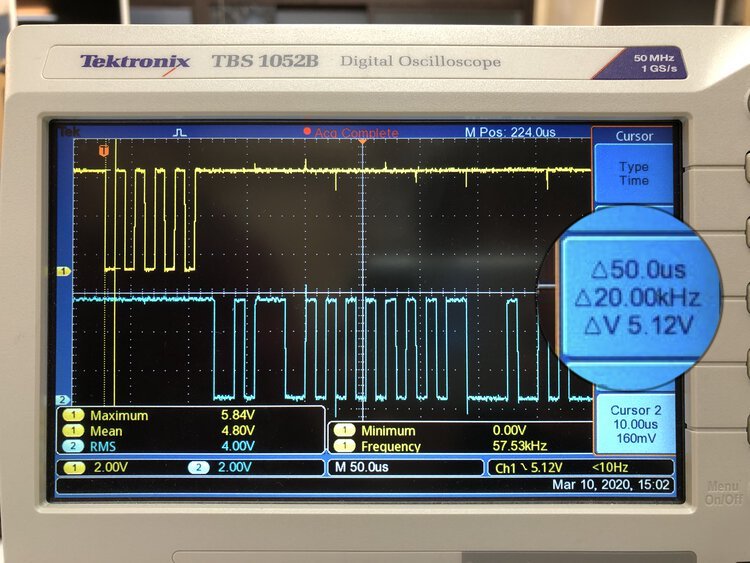
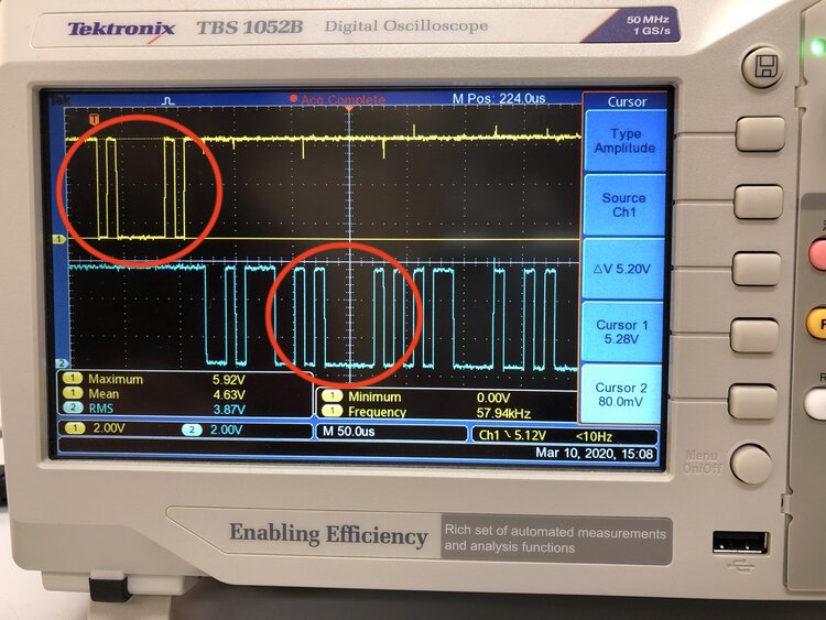
When running echo board and putting a character, the oscilloscope catches the wave like this.
The original echo program returns the message starting from "hello.t1614.echo: you typed ". I did not need these messages as I wanted to check simple in/out and how the ASCI character is displayed in oscilloscope.
I changed the "hollo.echo" program for avoiding unnecessary character from the stream. My program return just ":" and "echoed character" and "LF: newline character")
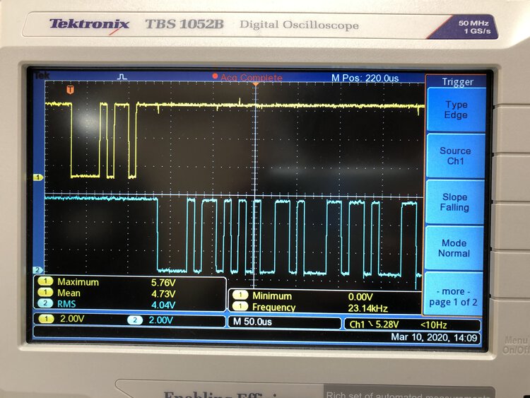
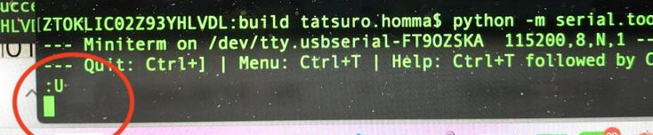
This is the outcome when I typed "U" as the first input character of echo program.
In ASCII table, "U" is "55" in HEX and "01010101" in binary code.
signal sequence is 50.0us. A frequency is : 1 second / 50.0us(0.000005 seconds) = 20.00kHz
voltage is 5.12V
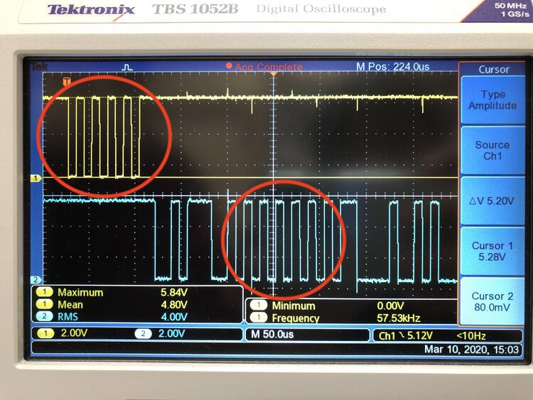
These area looks to contain "01010101" (equals to "U" in ASCII).
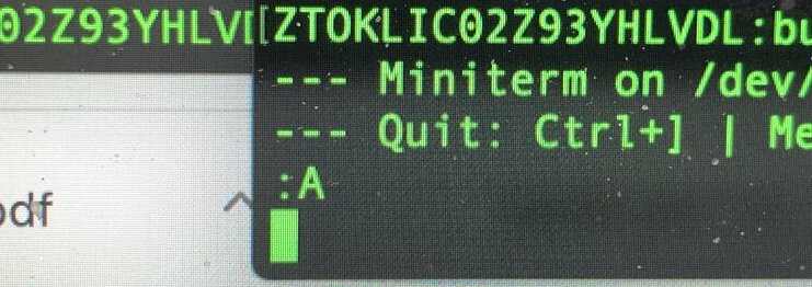
This is the outcome when I typed "A" as the first input character of echo program.
In ASCII table, "A" is "41" in HEX and "01000001" in binary code.
These area looks to contain "01000001" (equals to "U" in ASCII).
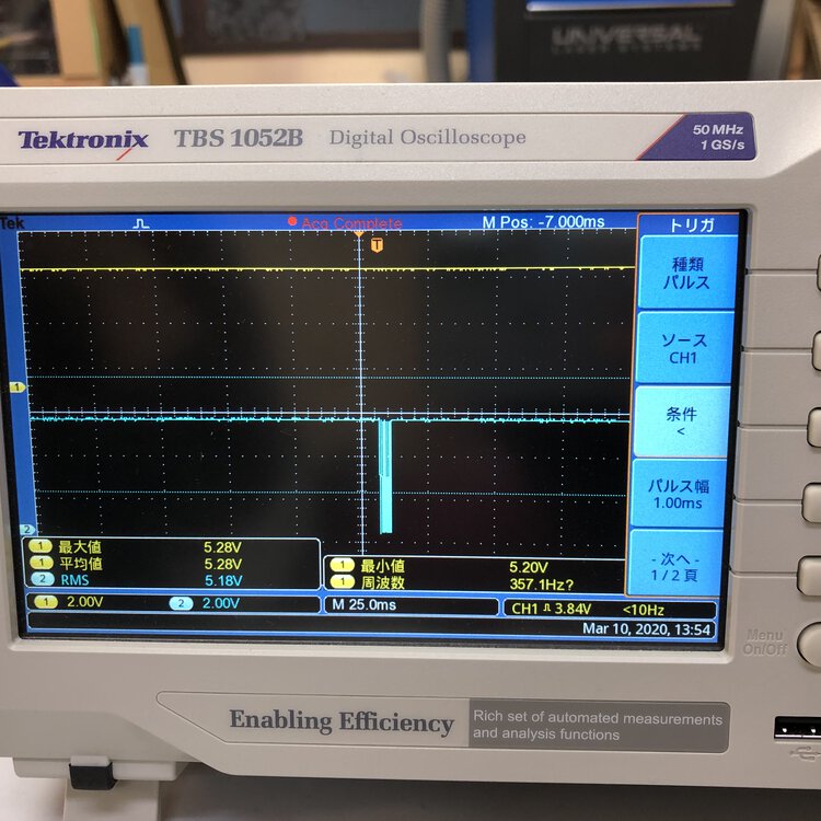
I tried to check the output of the echo board in the case of input the first character as "A".
I reconnected the Ch1 to the RXD of FTDI using extension.
This captures only output from echo board
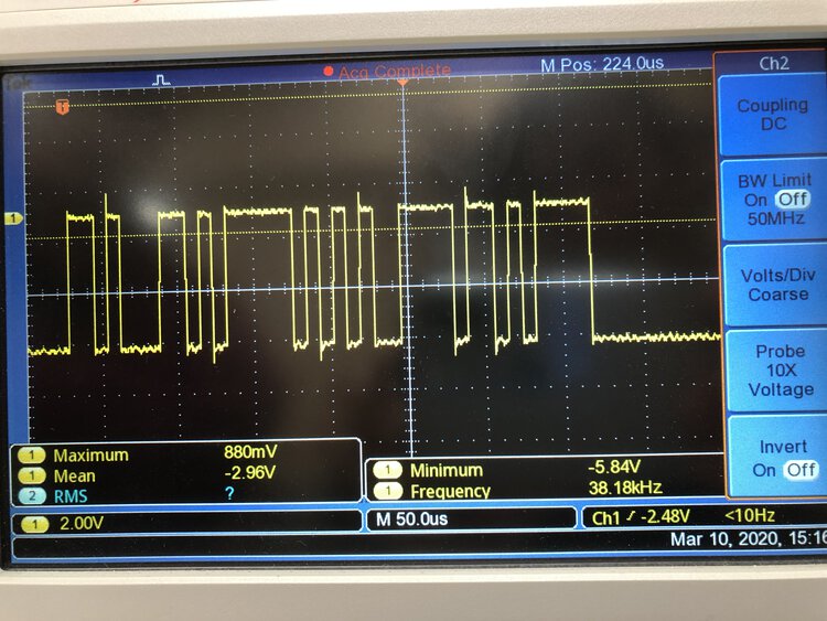
":" is "3A" in HEX and "00111010" in binary code.
"A" is "41" in HEX and "01000001" in binary code.
"new line(LF)" is "0A" in HEX and "00001010" in binary code.
THese binary code represents the voltage of the wave in oscilloscope, I have not been able to grab a manner to assign these binary signal as of 11 Mar 2020 though.