
computer-controlled machining (week07)
Group Assignment
- test runout, alignment, speeds, feeds, and toolpaths for your machine
Endmill
Thankfully, Fablab Hamamatsu accepted and allowed us to use Big CNC machine.
- Material : lauan plywood, 12mm thickness
- CNC router : ZN1325 at fablab Hamamatsu “Take-Space”
- Tool path maker : Vectric Cut2D Pro
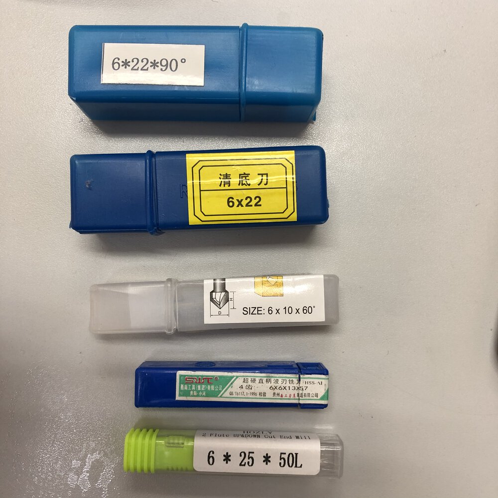
CNC router's endmill shank diameter is 6mm. So, we (my instructor, Tamiya-san) and I prepared to bring mills those shank diameter is 6mm with us.
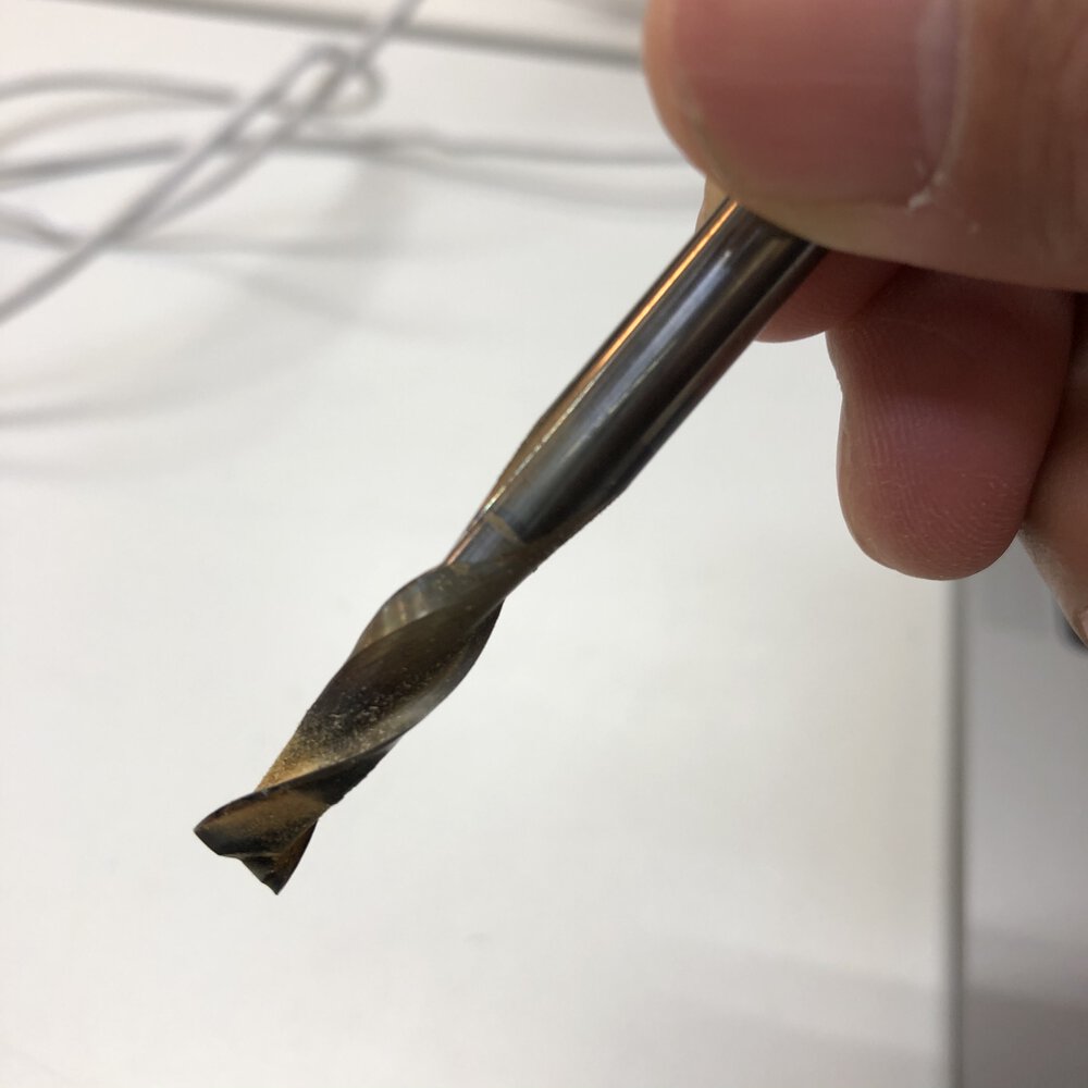
Upcut, 2 Flut
- delamination and burrs on the surface of material
- the bottom of material would be smooth
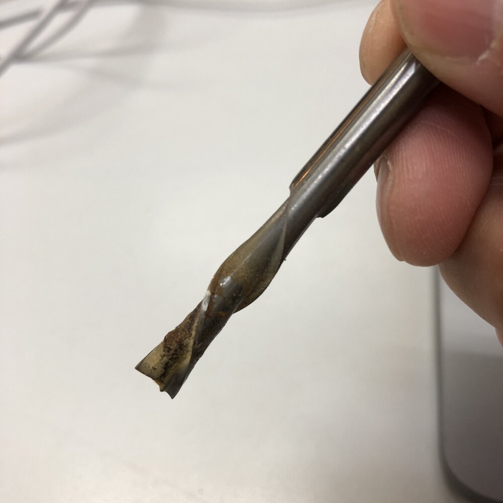
Downcut, 2 Flut
- the surface of material would be smooth
- delamination and burrs at the bottom of material
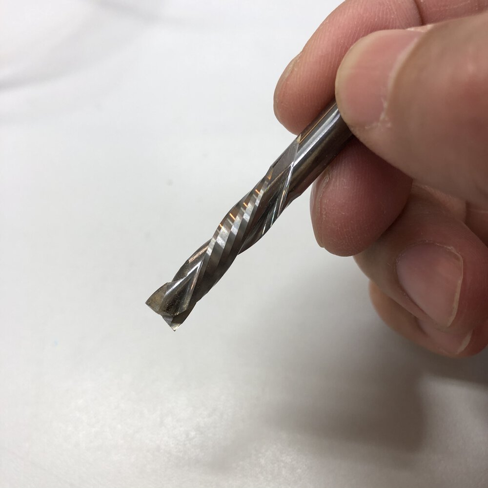
Compression, 2 Flut
- the surface and the bottom of material would be smooth
The cost of compression mill is much expensive than downcut or upcut.
CAM Setting
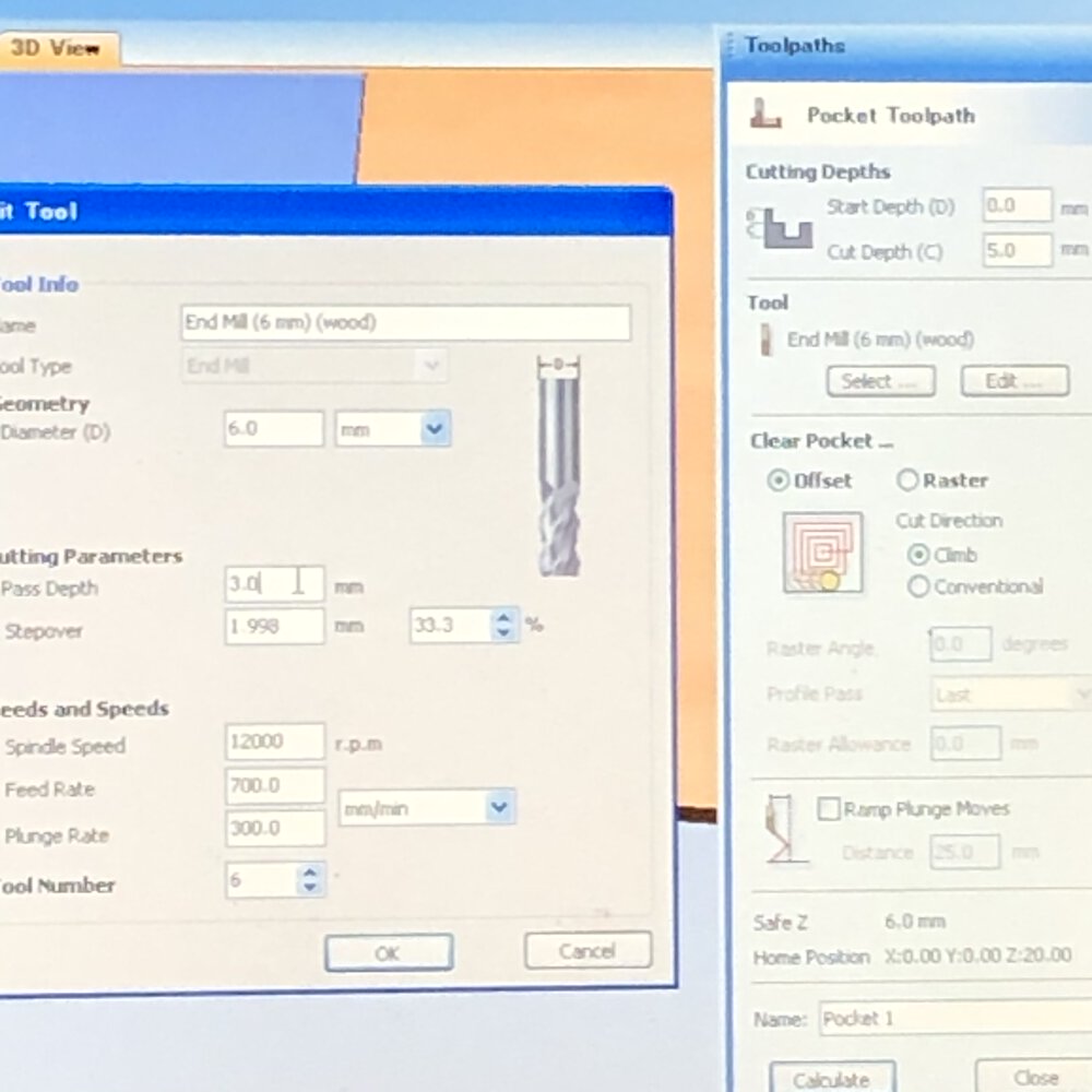
- Spindle speed = 12000 rpm
- Feed rate = 700.0 mm/min
- Plunge rate = 300.0 mm/min
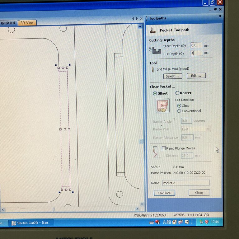
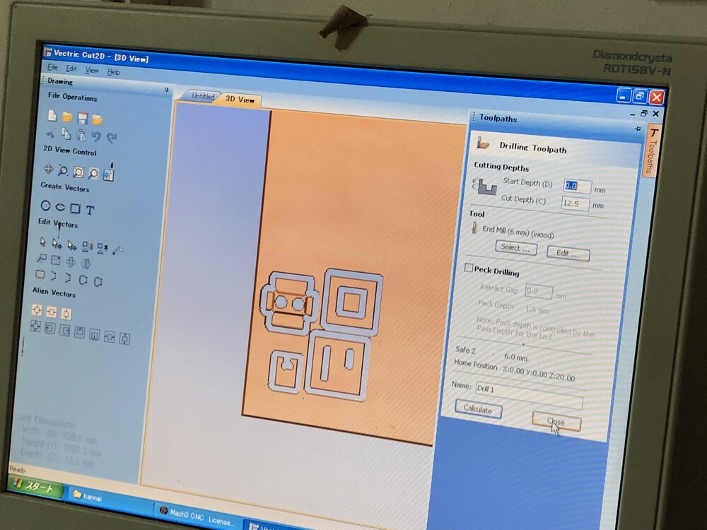
Making pocket, I used following settings.
- Start depth = 0.0mm
- Cut depth = 4mm
- Clear Pocket... = offset
- Cut Direction = Climb
Tool path
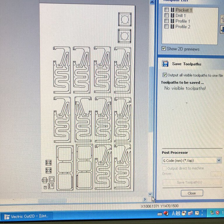
CAM toolpath is made by "Cut2D". I ordered and distributed the image to physical area of plywood board.
Cut2D supports move the path image to a specific position, edit path, making tab and export the data to .tap file (G Code) etc.
Preparation and Mill

For safety, wearing
- cover glass
- headset
- (mask)
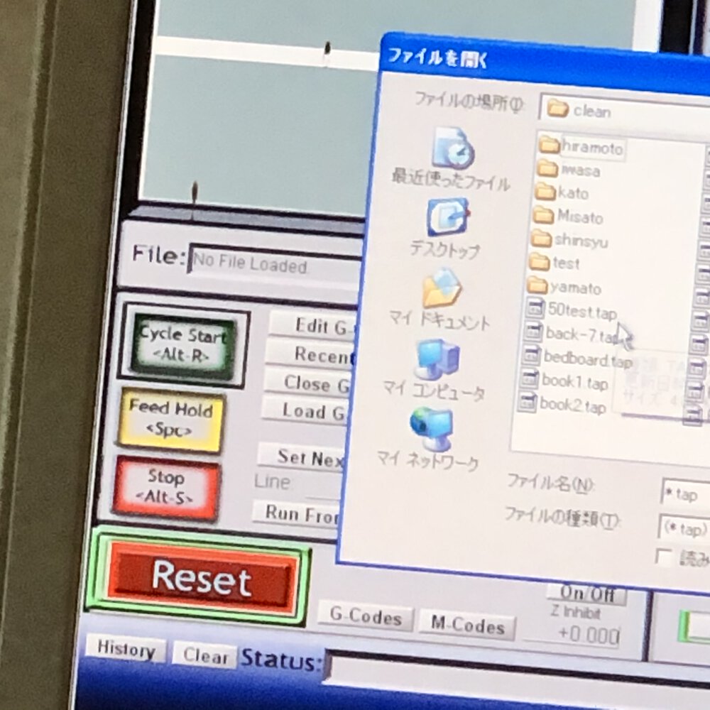
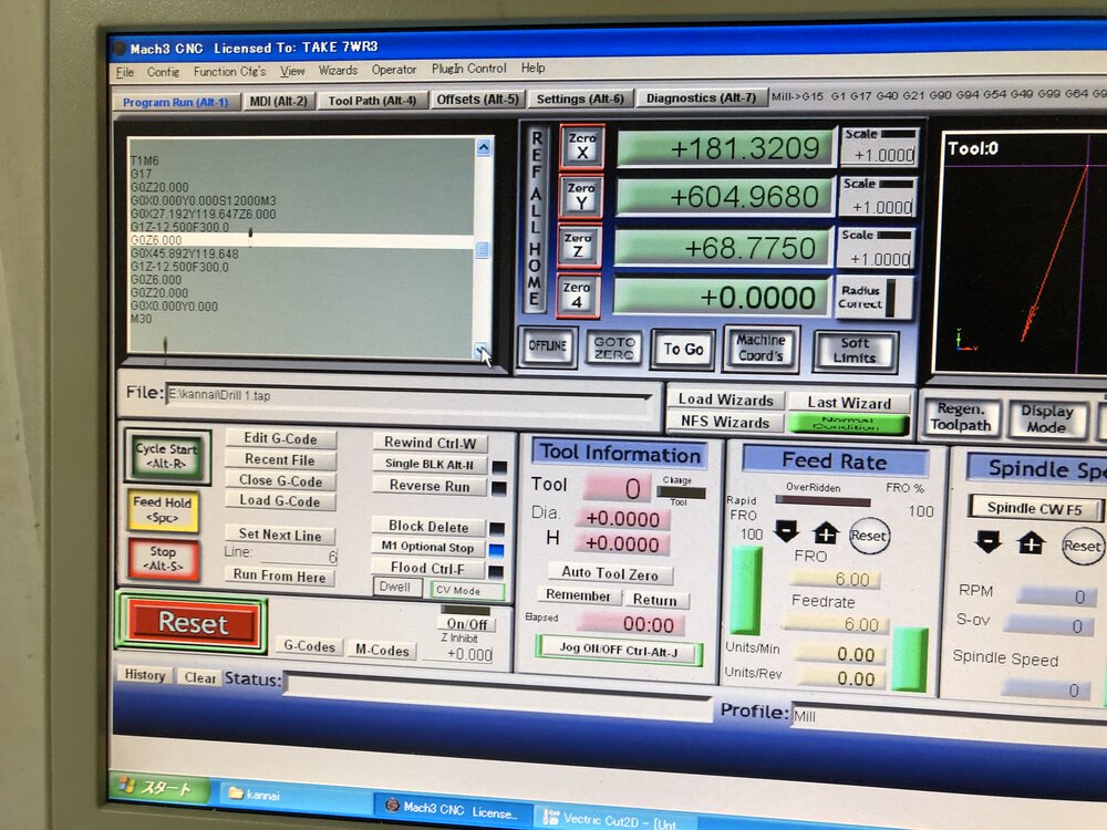
Import G Code(.tap file) at the button of "Load G Code"
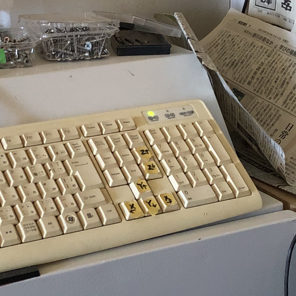
Start and reset buttons are both for CAM software and hardware button. Also, manipulating the XYZ axis are controlled by keyboard.
Step to setup the origin of tool is as follows
- Move the mill to the left - under corner of the material
- set origin (zero) of x axis and y axis
- check z axis hight by gently pushing the Down keys. The appropriate height of z axis is checked by news paper between mill and material board, then set origin(zero) for the tool.
Test Cut
As my design(speaker will use "inner cut", "outer cut", "slit with dog born joint", "pocket with dog born joint" and the "section of pocket", I tried to pick them from my design and tested it.
As a) pre-test cut by laser cutter did not work well for confirming tightness of joint and b) my material of wood board were changed due to sold out of 15mm of MDF(that was original plan), I need test cut to confirm how ZN1325 works when cutting 12mm of lauan plywood.

1) top square - 30mm of inter cut and 50mm of outer cut.
2) bottom square (insert slit) - 50 mm outer cut, 36 + 6 mm length of 7.5mm slit, 20 + 6 mm length of 7.5mm slit.

3) dog born slit - 7.5mm of width and 12mm of depth.

4) insert slit - cable terminal that has insert parts. Insert length of top and bottom parts are 15mm. insert length of left and right parts are 7.5mm.
insert part is to be cut by "pocket cut". The thickness after pocket cut is expected to be 7.5mm. That's why I setup pocket cut depth as 4.5mm(subtracted from 12mm of plywood total thickness = 7.5mm). 7.5mm of thickness will be tightly combined to dog born slit of 3).
I converted svg file to .ai file (as Cut2D did not accept svg file directly, I needed to change line color, thickness of line, path connection etc. on Adobe illustrator.
1) outer cut and inner cut.
Outer profile and inter profile can be cut off almost same cut line as once what I designed.
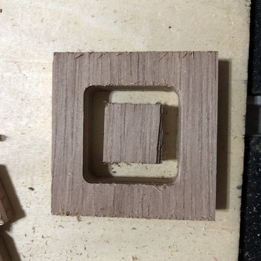
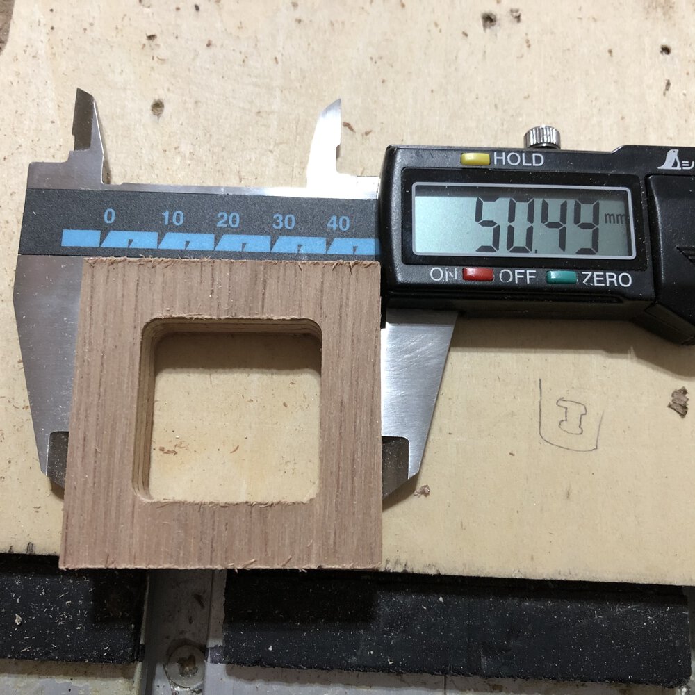 50mm design for outer cut is cut off by 50.49mm.
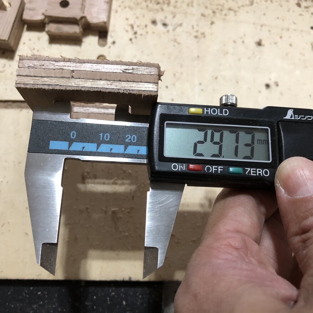 30mm deign for inner cut is also cut off by 29.73mm.
2) + 4) joint(for speaker cable terminal) and insert slit / drill
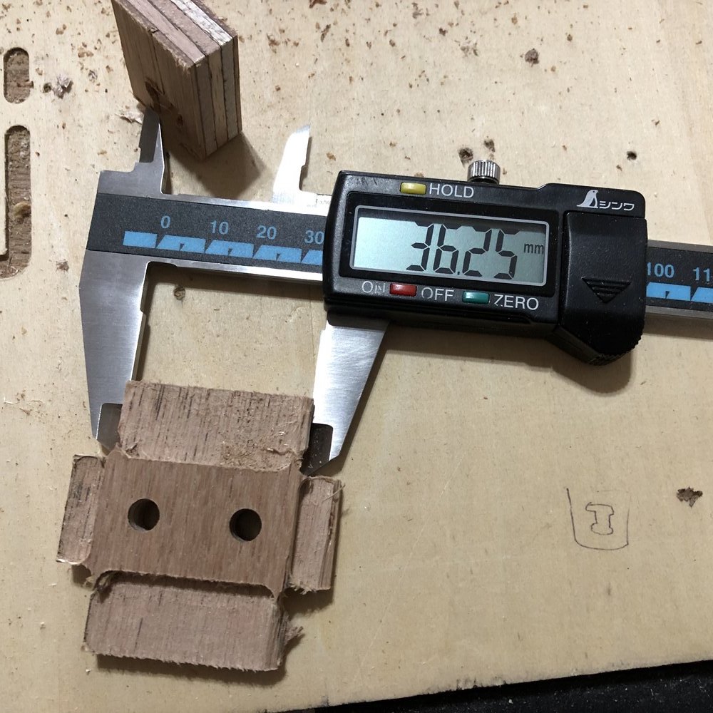
36mm length of slit design was resulted in 36.25mm.
Also, 6mm diameter of Mill can just drill more than 6mm diameters hole.
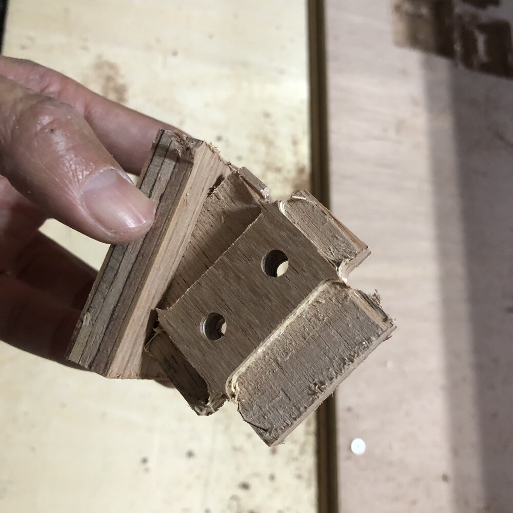 The slit length looks to be enough as I considered diameter of mill(cut off necessary length + mill's diameter). However I could not insert the joint completely as the dog bone is too shallow and the remaining parts near by dog bone prevents inserting the parts.
So I changed the design and the deepen the dog bone.
The slit length looks to be enough as I considered diameter of mill(cut off necessary length + mill's diameter). However I could not insert the joint completely as the dog bone is too shallow and the remaining parts near by dog bone prevents inserting the parts.
So I changed the design and the deepen the dog bone.
 "deepen" the dog bone.
3) + 4) joint(for speaker cable terminal) and insert slit
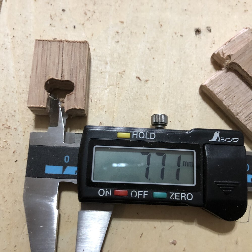 A design of 7.5mm of (female) joint slit width was resulted in 7.71mm.
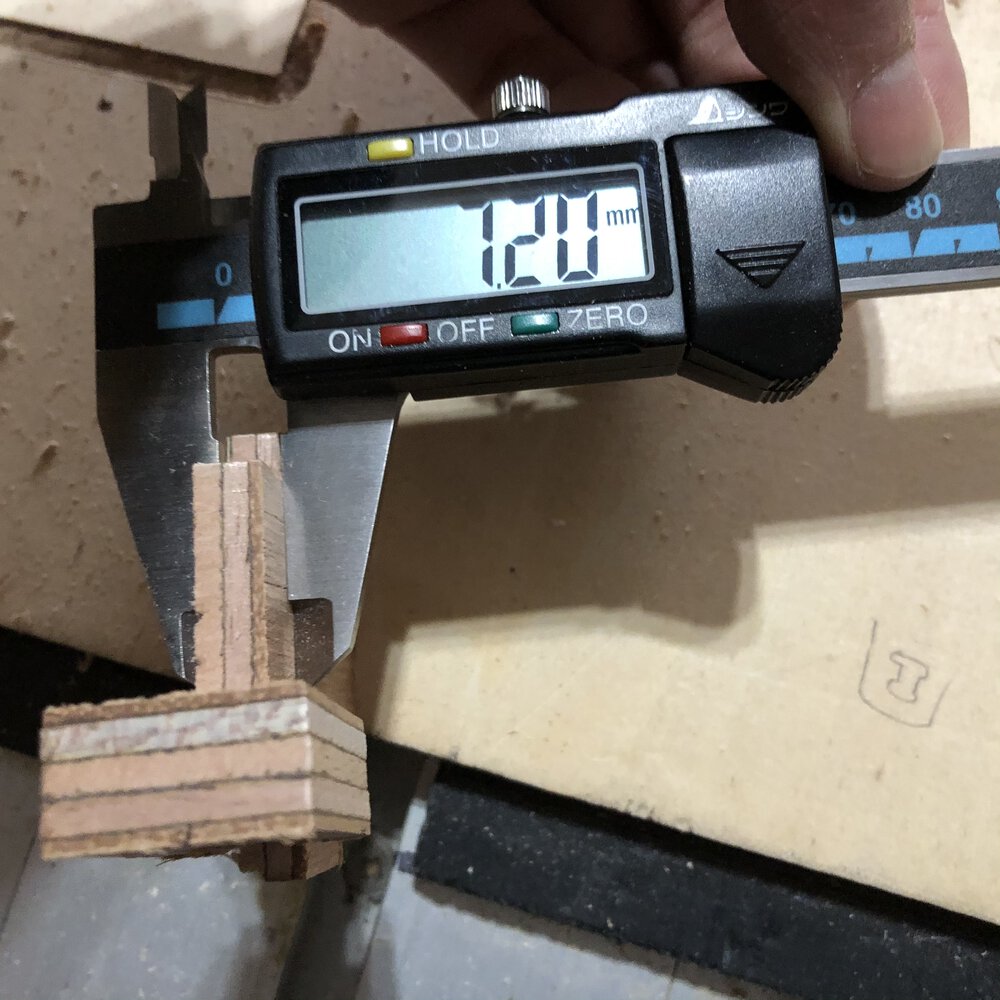 A design of 4.5mm of pocket cut (subtracted from 12mm of plywood thickness = 12 - 4.5 = 7.5mm is supposed to be remain) was resulted in 7.2mm.