11. Output Devices#
Neopixel (Oka)#
I mesured the power of Neopixel which I made for my final project. I attached the multimeter between the battery and power pin of MCU board.

It showed 58.9mA in the picture.but it was unstable actually so it went up and down between about 50mA and about 60mA.
I checked only output devices as well. attached the multimeter into the circuit to measure.

For two LEDs. 11.7mA
I also checked the differences among the different colors, red, green, and blue.

Red, 6.02mA

Green, 5.79mA

Blue, 5.92mA
Red was the highest in the three. And the sum of Red and Green would be 11.81mA. this is not so different from the value of the complex of Red and Green which I measured before single LED. So I guess the power consumption of the MCU board might be around 40mA to 50mA.
Measuring Power Consumption (Tsuchiyama)#
I measured the power consumption of the circuit that operated the stepper motor.
I measured the circuit that I made this week.

Digital Multimeter (CRENOVA: MS8233D)#
I used a digital multimeter (CRENOVA: MS8233D) to measure power consumption.

① Measurement of Total Power Consumption#
I measured the current flowing through the entire circuit that was initially created.
※ At this time, connect the red test lead of the digital multimeter to the input terminal of 10A.
The total current flowing through the Arduino, motor driver and steppermotor was “〇〇A”.
② Measurement of Motor Power Consumption#
Next, by removing the motor from the measured circuit, the current flowing through the motor was measured from the difference in power consumption.
The current flowing through the motor was “〇〇A”.
And from the voltage (12V) in the circuit and the current (〇〇A) flowing through the motor, I measured the power consumption required to operate the motor.
1 2 3 4 | |
The power consumption was “12V x 〇〇A = 〇〇W”.
Oguri#
I checked the power consumption of servo motor, SG90-HV (continuous rotation).
Testing diagram is shown as below.
SG90-HV is controlled by ESP32, which was connected to USB port of MacBook Pro.
( Therefore, consumed power by ESP32 was from MacBook Pro. )
Drive power for SG90-HV was supplied from four AA batteries through voltage regulator.
Drive current of SG90-HV was measured in terms of the voltage difference between
“point A” and “point B” in the diagram, which was the voltage drop through 1 ohm resistor.
Supply voltage for SG90-HV was measured between “point A” and “point C”.
Drive speed of SG90-HV was controlled from iPhone via BLYNK BLE
( potentiometer could be used,
but BLYNK BLE was good way to avoid the noise issue from bread board wiring. )
Two levels of load was applied by finger during the operation, namely, “No Load” and “Heavy Load”.

Conclusion
In case of the “Heavy Load”, the power consumption was 0.93 watt.
Just for reference, in this case, the power consumption by 1 ohm resistor was 0.06 watt
, which is considered to be small enough ( could be ignored ) in this measurement.

Yume#
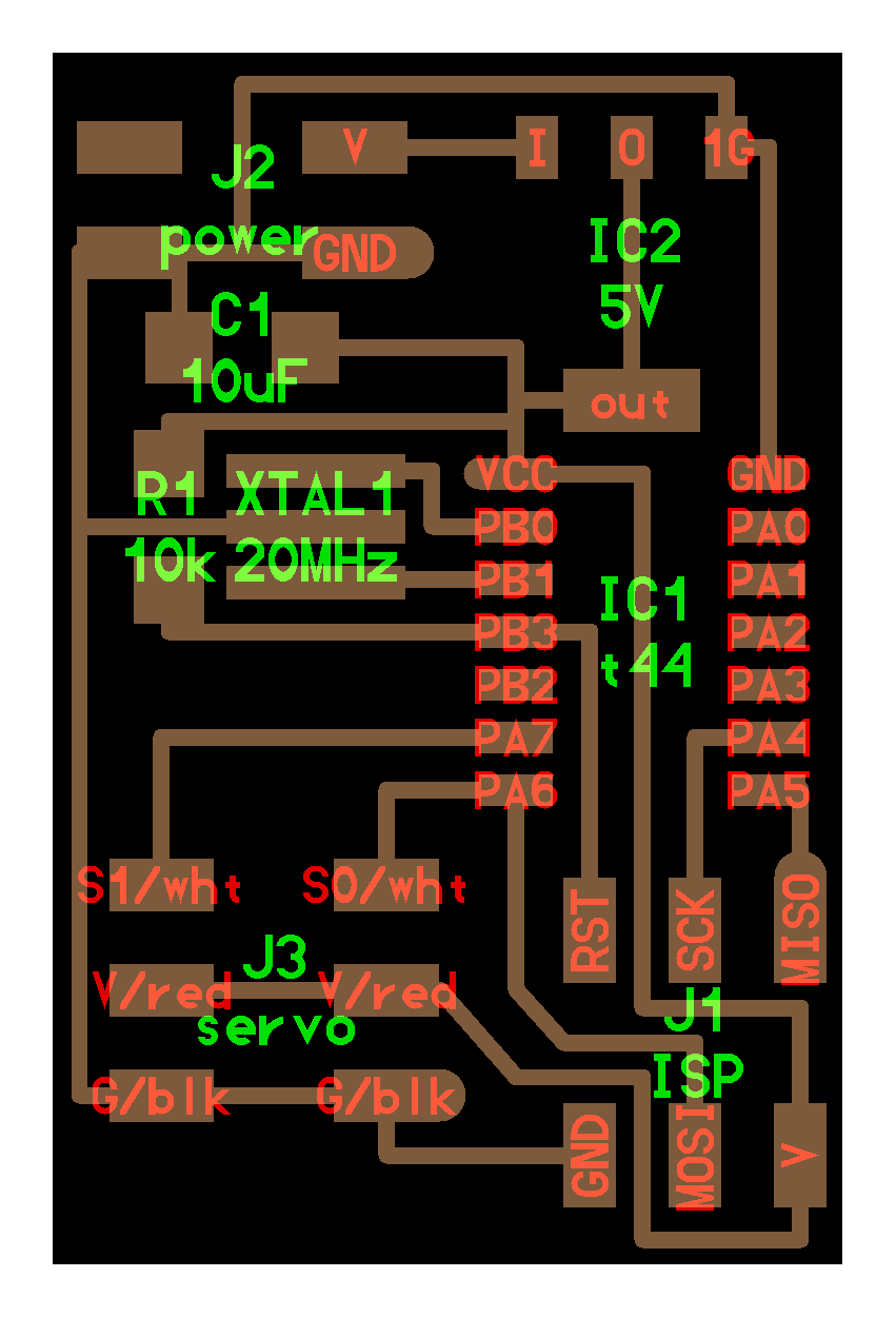
This week I worked on servo motor SG90 (datasheet) by Tower Pro Pte Ltd as an output device.

Prototype on a breadboard#
I refered to this board to connect these components on a breadboard:
- ATTiny44 * 1
- 20MHz resonator * 1
- 10mF capacitor * 1
- 10kOhm resistor * 1
- SG90 servo motor * 1
- FabTinyISP * 1
- FTDI cable * 1 (for power supply)
Instead of using 9V battery and a regulator, I used FTDI cable to obtain electricity.
At first, I soldered ATTiny 44 and resonator onto PCB boards so they fit onto the breadboard.
For the resonator, I used number 1-3 pads on the board. The soldering process was very challenging…

Then I connected all the parts.
I used PA6 to connect to the PWM pin of 1 motor.

Run the sample code#
After connecting, I plugged FabTinyISP into my computer, and tried to run the sample .c file and .c.make file of hardward PWM.
When I ran $ make -f hello.servo.44.c.make in terminal, I got an error message:
1 2 | |
Then I discovered that the .c.make file I downloaded was named hello.servo.44.make. So I changed the name into hello.servo.44.c.make and it worked.
Then I ran
1 2 | |
and the motor moved.
Test the current and voltage in the circuit#
To see how much electricity is consumed when the motor is moving, I used a multimeter to test the current and voltage going through the circuit.
The multimeter is connected in between the power supply, and the wires going in to VCC and GND of the breadboard.
Current#
Firstly I tested the current.
When there is no motor connected, the current reads 0.013A.
When there is motor connected, the current fluctuate according to the movement of the motor.
The current should be the same when the motor is moving. However, since the timing of measurement is not perfectly tuned to the movement of the motor, the number fluctuate.
The current goes up to 0.279A in the video, and that represents the current consumed in the whole circuit when the motor is moving.
Therefore, the current the motor consumed when moving is
0.279 - 0.013 = 0.266 A
Voltage#
Then I tested the voltage.
When there is no motor connected, the voltage reads 5.12V.
When there is motor connected, the voltage fluctuate according to the movement of the motor.
The voltage goes down to 4.86V so I assume it is the voltage level when the motor is moving.
There for, the voltage cosumed by the motor when moving is
5.12 - 4.86 = 0.26 V
Kimura#
I measured the power consumption of the DC motor.
Before that, I had a remote lecture by Mr. Yamamoto from FabLab Kamakura using Zoom.
The picture below is a screenshot of the lecture.

As advised, I put a 1 ohm resistor in the middle of the wiring to the motor as shown in the photo and connected both ends of it with a prog.
Note that the GND side of the blog is connected to the motor driver side, not the Arduino side.

The purple waveform of the arrow is the difference between A prog (light blue) and B prog (yellow).
The scale of oscilloscope is set to 1V, so it should be about 0.75V.
To get amperage, you can divide the volt by ohms.
0.75/1 = 0.75
While it is rotating steadily, it is consuming about 0.75A of current.
However, I just measured it and noticed that when it first started up, it swung almost twice as much, so it must be consuming a good amount of current.

To confirm, I also measured it with a multimeter. The value was about 0.712V, so it almost matched the oscilloscope data.
