I thought about this from the perspective of a remote student...
I’ve had a really hard time getting involved in the Fab Academy due to lack of a la in my home country Honduras. I tried different solutions but the fact that
I didn’t have an instructive on a fiscal form brings a lot of challenges. One of those challenges was acquiring my own CNC and learning how to use it by myself.
In my opinion the CNC router is the machine with the biggest learning curve. One of the things that took me weeks of researching to slightly understand was the bits.
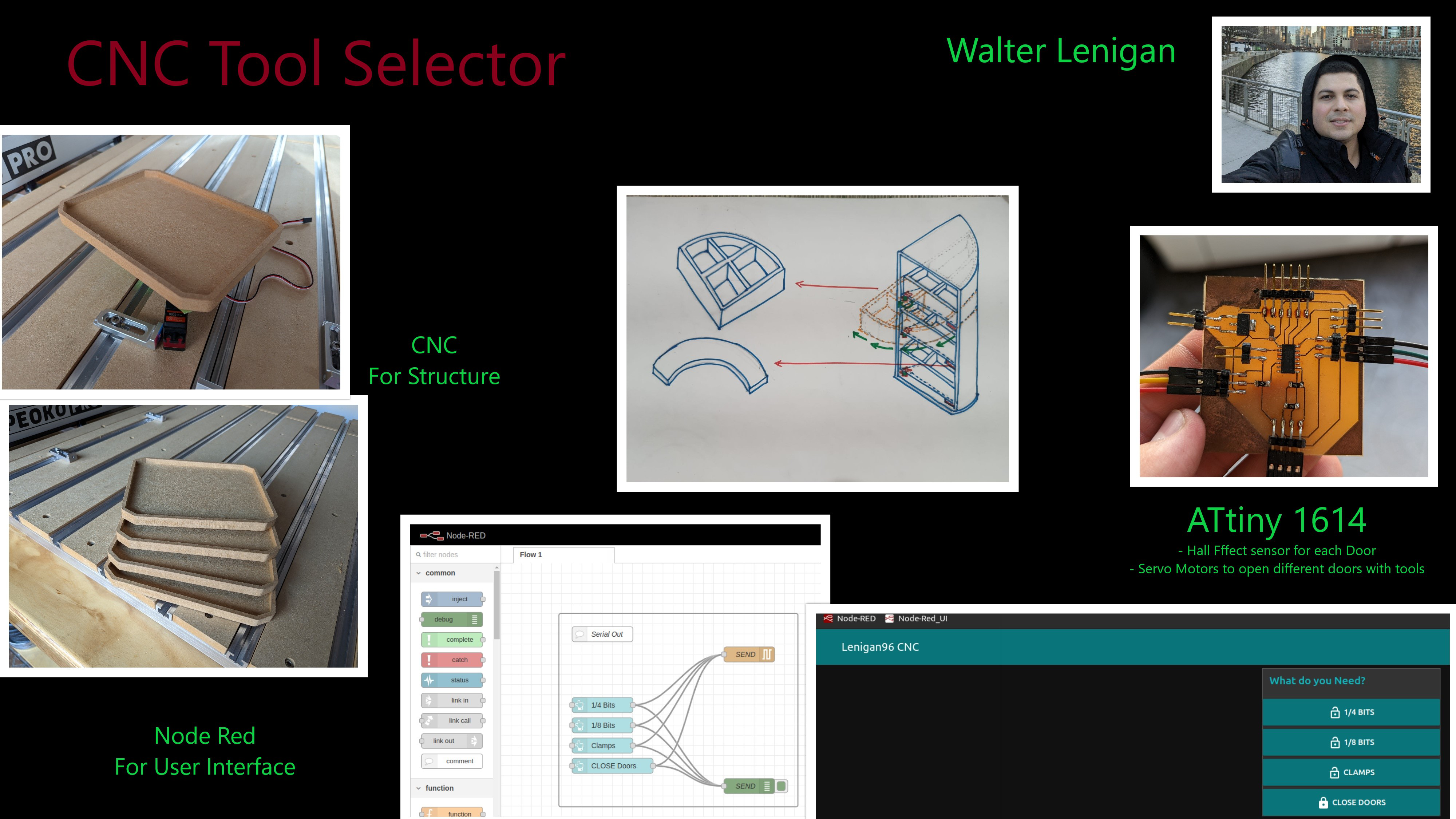
The idea is to create a smart tool box for my CNC
The first spiral of the idea is creating a little box that can tell where I can find the 1/8 in., ¼ in and the clamps. I’ll use my Raspberry
Pi 4 equipped with Node Red to eventually give it the capabilities of communication with someone out of the local server with Node Red.
CNC Smart Box
Log #1
What does it do?
The CNC Smart Box is an intelligent storage system designed to organize and automate the selection of CNC cutting tools (end mills). It addresses the steep learning curve beginners
face when selecting tools by physically categorizing them and guiding the user via a digital interface.
Functionality: It features three servo-controlled drawers (categorized for 1/4" bits, 1/8" bits, and Clamps, etc.).
Control: Users can open specific compartments using physical buttons on the box or wirelessly via a web-based User Interface (UI) hosted directly by the box.
Who’s done what beforehand?
If I’m not mistaken, I believe I saw a group project in the academy the looked like a vending machine for CNC bit storage. I tried to find the documentation
but fail. Regardless of this my project what to add the possibility to teach other about the bit selection. On future spirals of this project, it could help
by adding more variable into play.
Existing Market: Industrial CNC machines use Automatic Tool Changers (ATCs), but these are expensive and complex mechanisms not suitable for desktop beginners.
Research: Studies exist regarding AI and Machine Learning for predictive maintenance in CNC, but they focus on industrial efficiency rather than beginner education
The Gap: There was no existing "smart storage" solution specifically designed to teach and assist desktop CNC users (like Shapeoko owners) with tool selection.
What did you design?
I designed the entire system from the ground up, including:
Mechanical Structure: A glueless, interlocking box designed in SolidWorks. It uses "dog bone" fillets to allow flat parts to slot together despite the round CNC bit radius
Electronics (Go to WEEk 6 for more Info.): A custom single-layer PCB designed in KiCAD that integrates the microcontroller (XIAO ESP32S3), power distribution, and servo headers.
Back-end: C++ firmware for the ESP32S3 to handle servo logic and create a Wi-Fi Access Point.
Front-end: An HTML/CSS web interface embedded in the code for wireless control.
What sources did you use?
I designed the entire system from the ground up, including:
Gemini 2.5 Pro: Used to generate the Access Point (AP) code logic to allow the ESP32 to work without a router.
Carbide 3D & Shapeoko Community: For feeds and speeds data and machine specifications.
Sienci Labs: For specific compression bit parameters.
UNSW Sydney: For theoretical background on tool geometry (end mills vs. drill bits).
What materials and components were used?
Structural Material: 3/4" Plywood (chosen due to availability, though it presented warping issues).
Electronics: A custom single-layer PCB designed in KiCAD that integrates the microcontroller (XIAO ESP32S3), power distribution, and servo headers.
Microcontroller: Seeed Studio XIAO ESP32S3.
Actuators: 3x Servomotors (MG90/SG90 style).
Board: Single-sided Copper Clad Board (FR1/FR4).
SMD Components: 1206 Resistors (used as jumpers), LEDs, Tactile Switches.
Other: 3D printed PLA filament for motor mounts, acrylic door, cardboard cover and hinges.
Where did they come from?
Plywood: Sourced locally (implied by the mention of "difficulty finding material... found plywood").
Electronic Components: Many components (like the XIAO and quality end mills) had to be ordered from abroad as high-quality components were difficult to find locally.
PLA PRO: had to be ordered from abroad as high-quality filament.
How much did they cost?
Item
Quantity
Unit Cost
Total Cost
Seeed Studio XIAO ESP32S3
1
$7.00
$7.00
Servomotors (MG90/SG90 Series)
3
$15.00
$45.00
Plywood Sheet (3/4")
1
$150.00
$150.00
Copper Clad Board
1
$15.00
$15.00
SMD Components (Assorted)
1
$20.00
$20.00
PLA Pro Filament (1 Kg)
1
$40.00
$40.00
GRAND TOTAL
$277.00
What parts and systems were made?
Made (Fabricated):
The main wooden chassis (CNC milled).
The PCB (CNC milled tracks and isolation).
Motor mounts and hinges (3D Printed).
Acrylic Door (Laser)
Systems Integrated:
Logic System: ESP32S3 handling inputs (buttons/web) and outputs (PWM for servos).
Power System: Custom PCB distributing power to the servos and MCU.
What processes were used?
Subtractive Manufacturing (CNC): Used a Shapeoko Pro XXL to cut the plywood structure and mill the PCB traces.
Additive Manufacturing (3D Printing): Used for small mechanical brackets.
Electronics Production: Surface Mount Device (SMD) soldering using solder paste and a hot air gun, plus hand soldering for the XIAO MCU.
Programming: Used the Arduino IDE to program the ESP32 and Wokwi for logic simulation.
What questions were answered?
Structural: Can a precise, interlocking box be made on a desktop CNC using lower-quality plywood? Yes, but it requires vacuum workholding and manual correction during assembly.
Electronic: Can a complex control circuit be made on a single-sided PCB? Yes, by using 0-ohm resistors as bridges/jumpers over traces.
Connectivity: Can the system work without an internet connection? Yes, by configuring the ESP32 as an Access Point (AP).
What worked? What didn’t?
What worked:
The Access Point implementation was highly successful; devices connected directly to the box without a router.
The PCB milling process was perfect, with clean isolation of traces.
The Onion Skin technique kept parts stable during CNC cutting.
What didn’t:
Material Quality: The plywood was significantly concave. Even with a vacuum table, it returned to its warped shape after cutting, making assembly difficult.
Servo Range: The standard libraries assumed 180-degree servos, but the purchased servos were 270-degree, requiring code adjustments to Pulse Width Modulation (PWM) signals.
Arduino Code Display
Arduino Code (Servo_Cal)
//Walter Lenigan - Fab Academy 2025

#include

Servo S_1;  // create servo object to control a servo

void setup() {

  S_1.attach(11);  // attaches the servo on pin 9 to the servo object
}

void loop() {

  S_1.write(65);    // Change the "65" to see # that makes the servo move to 90 deg.
}
WHow was it evaluated?
Simulations: Extensive CAD/CAM simulations (SolidWorks/Carveco) and code simulations (Wokwi) were run to verify logic and toolpaths before physical fabrication.
Functional Testing:
Electronics: Tested with a variable DC power supply to ensure no shorts before plugging in USB.
Software: Verified by connecting a smartphone to the "Lenigan96 CNC" Wi-Fi network and toggling drawers.
Mechanical: Validated by the physical fit of the dog-bone joints and the smooth operation of drawers.
What are the implications?
This project demonstrates that high-level "smart workshop" tools can be fabricated using low-cost, accessible microcontrollers like the ESP32.
It implies that the barrier to entry for CNC machining can be lowered not just by better machines, but by creating an ecosystem of smart,
educational peripherals that guide the user.