Week 07
Computer-Controlled Machining
01
Assignments
- Group assignment.
- Test runout, alignment, speeds, feeds, and toolpaths for your machine.
- Individual assignments
- Make (design+mill+assemble) something big.
Software
- Fusion 360
- LighShot
- ArtCAM
- Artesoft Mach 3
- Gimp
- AutoCAD
- WinRAR (discontinued)
- SketchUp
- Spin 3D Mesh Converter
Download File
02
Assignments
Group Assignments (1)
-
Test runout, alignment, speeds, feeds, and toolpaths for your machine.
The assignment consists of the test run, alignment, speeds, feeds and toolpaths of our machine.
We do not have the model of the machine, since it was specifically ordered to be manufactured in a workshop (IJERSA) and the FabLab was donated with some limitations of physical structure and software, for which we have had some problems in achieving the proper calibration and configuration.
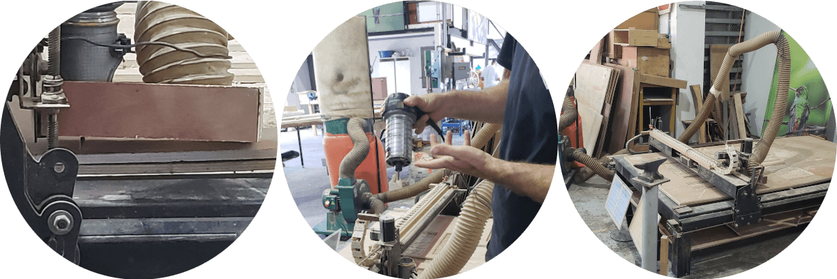
Equipment Description (mm):
- Structure of 100x100x4.76 square steel tubes, painted black.
- Bed: width (1447.80) x depth (2603.50) x height (200).
- Structure of 100 x 100 x 4.76 square steel tubes, painted black.
- Transverse reinforcements of 25.40 x 50.80 x 4.76 steel tubes.
- Uses 19.05 x 19.05 x 4.76 steel angles that serve as guides on pulleys and chains for X and Y axes.
- It has a wooden structure on each side to hold the cables and tensioners corresponding to the axles.
- Under this structure there is a bed made with 50.80 x 50.80 x 4.76 steel angles with oscillating wheels where the plywood pieces are placed for later use.
The machine is already configured to work in a certain way and we were advised not to change any detail, because some characteristics are to be defined or detailed and it is not recommended to make this change from Match 3 because we are in danger of deconfiguring all the equipment.

Usage procedure:
- Use of safety equipment: eye, ear and nose projectors.
- Screw the plywood in, taking care that the drill bit does not pass over the screws, since we would lose the tool.
- Connect the usb cable to the laptop.
- Open the Match 3 software.
- Connect the CNC power cable.
- Load the Gcode of the file by importing it.
- Reset to Match 3 until it changes color from red to green.
- Since the 0,0,0 of the bed (lower left) is not the same as that of the wooden bed and also in the program (Table Display), the position of the drill bit must be manually configured. cut on the work surface (wooden bed).
- Reset to Match 3 until it changes color from red to green.
- Connect the vacuum cleaner.
- Turn on the router.
- Send the file to Cicle Start.

The box that collects the wood dust must be ± 20 mm from the plywood, otherwise it will trip over the cuts made, since it is tilted because it is attached to the router with wires.
You should always be aware of the operation of the machine and have the mouse pointer ready on the STOP option, just in case.
The entire model should be accommodated in the lower left, since the coordinate origin of the metal bed is ± 165 mm on the X axis.
The vibration of the Cnc generates an additional width of cut of ± 1 mm, which can be adapted in the 3D model to take this difference and that is compensated in the final product.
Care should be taken to check each piece as soon as it is finished cutting, as some of them tend to buckle on their own, especially those that are very long in size.
Individual Assignments (2)
-
Make (design+mill+assemble) something big.
For this assignment I wanted to develop something unique, in principle that could sustain itself:
- 2D design in AutoCAD.
- 3D modeling in Fusion 360 and export as .obj.
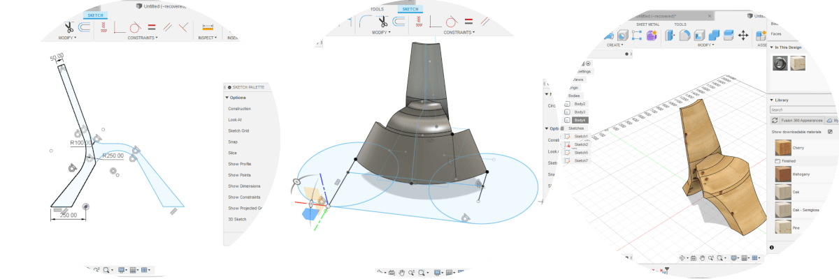
- Open . obj in Slicer and make a radial layout and get the .dxf cut planes in a 1200 mm x 2400 mm page layout.
- Import the .dxf in ArtCAM and configure the necessary parameters to make the respective cuts, this is where the cutter is set: cutter, speed, depth per step, etc.
- Save the file generated in ArtCAM as a Gcode.
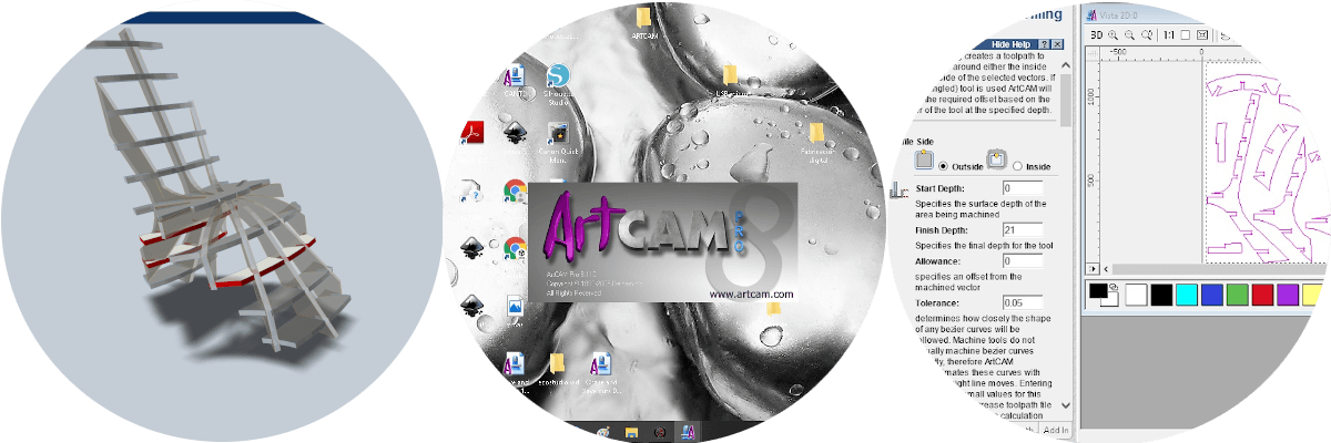

- Import the gcode file in Match 3, which is the display for the CNC, here the values for the coordinates and position of the cutter with respect to the file and the plywood sheet are set.
- I also repeated the same procedure above but starting with the .obj model in SketchUp to generate 2 reinforcement cross pieces and get to manually edit the gcode at the cut heights.
- The entire cutting process took 3:24 hours.

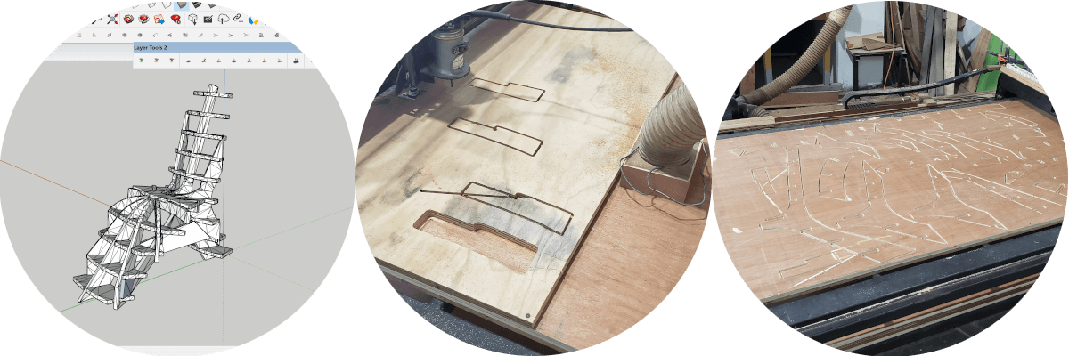
- Once all the cuts have been made, I began to assemble the chair, according to the preview previously generated in Slicer, this process took about 7 minutes.

Inconveniences - Delays
- The only drawback is the fact that the envelope that we place on the metal structure to receive the cutting material, as it is only attached to the 4 corners, the plywood, having to buckle due to its natural properties, must leave a high tolerance in the parameters set in ArtCAM, in some occasions it does not finish making the deep cut and in others it cuts too much.
