This page presents the assignments for week 6 of Fab Academy 2020: “Electronics Design”.
To do list:
Group
- use the test equipment in your lab to observe the operation of a microcontroller circuit board
- redraw an echo hello-world board,
- add (at least) a button and LED (with current-limiting resistor),
- check the design rules, make it, and test it,
- extra credit: simulate its operation
Week 6 files:
RedrawHelloBoard.kicad_pcb (own work)
RedrawHelloBoard.pro (own work)
RedrawHelloBoard.sch (own work)
Week 6 "hero shot":
Table of Contents
Individual assignments
Redraw an hello-world board
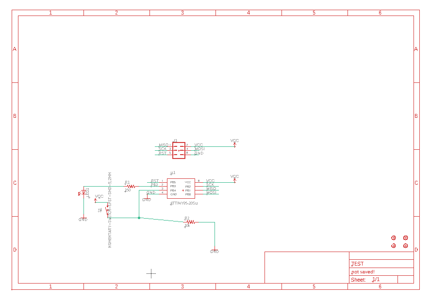
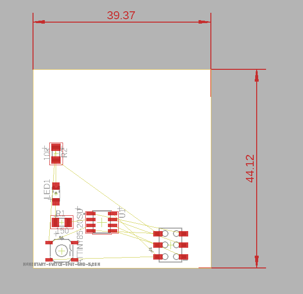
Using Eagle software
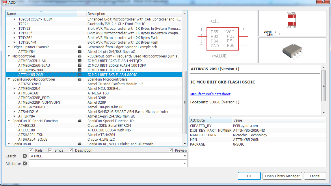
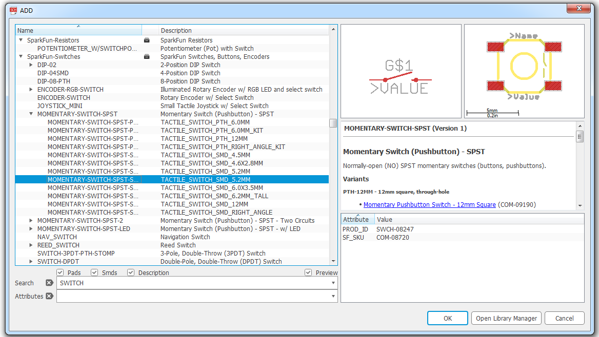
I create a new project in Eagle.In the schematic file I used the "place symbol" tool add the components needed to the drawing board.
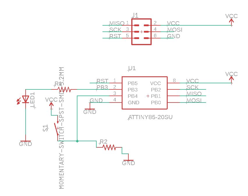
After adding all components, I used the "wire tool" to connect component.
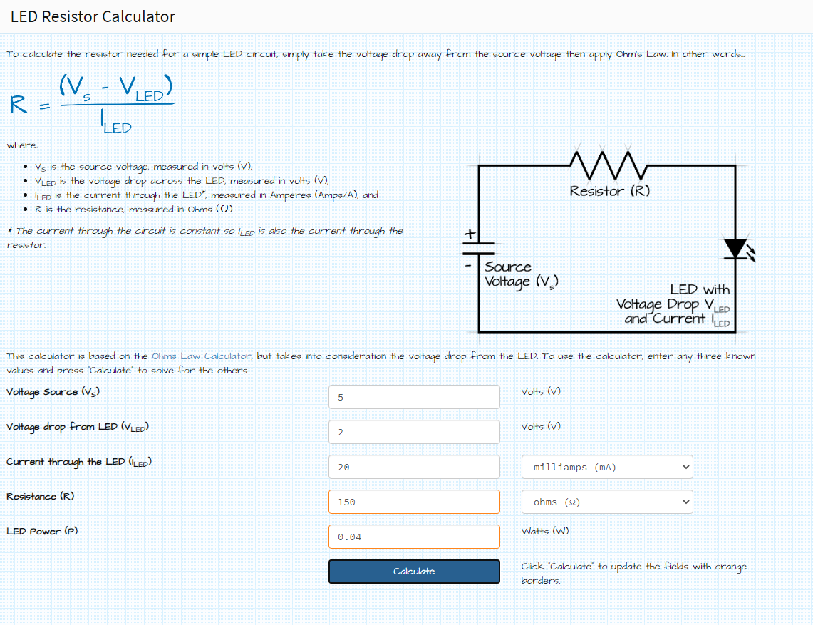
I checked the LED datasheat and use a website to calculate the appropriate value to use for its resistor.
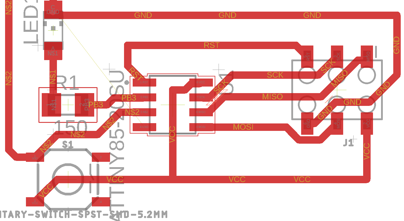
I tryed several combination for components wiring and positioning.
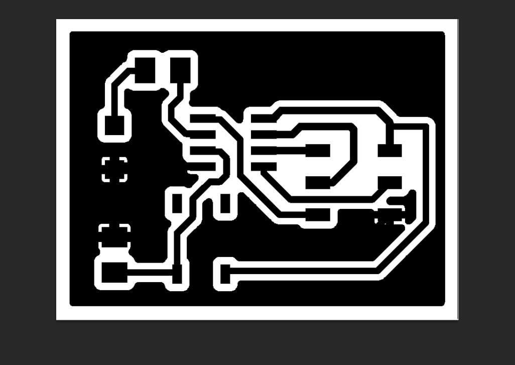
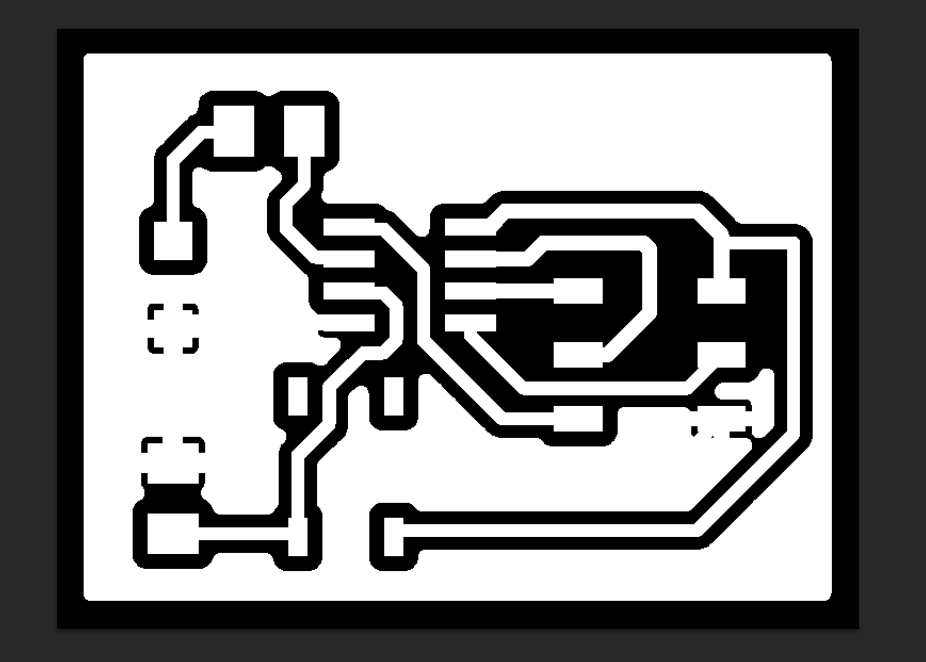
Then I generated a black and white picture.
Finaly I inverted the black and white to get a picture ready for engraving on the laser cutter.
Make it
Laser cutter
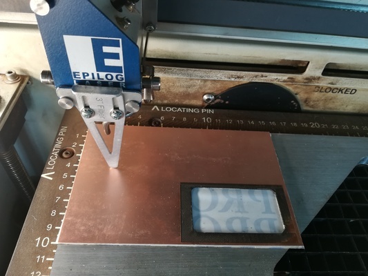
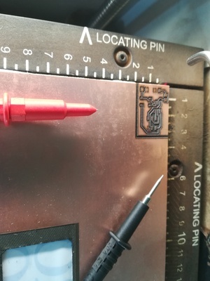
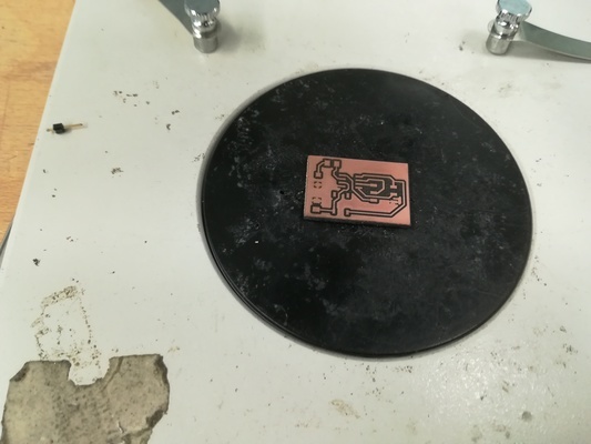
I used one job on the laser cutter to engrave the copper with the layout produced in Eagle.I used a beeping oscilloscope to check that the trace have been correctly made before cutting the fiberglass.
I then used 20 simple jobs to cut trough the fiberglass of the board.
Copper engraving
Fiberglass cutting
Soldering
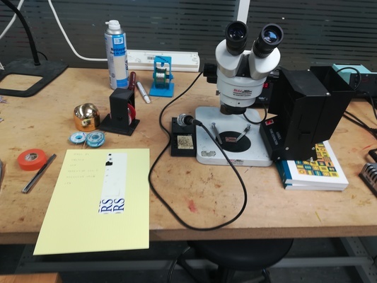
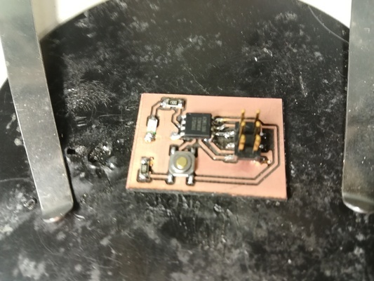
I used the microscope to search for copper hairs.I used beeping oscilloscope for more testing of the traces.
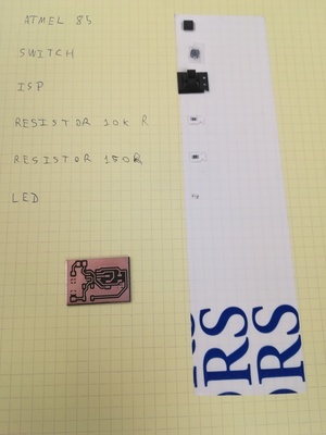
I then glued all needed components on a "to solder list" paper.
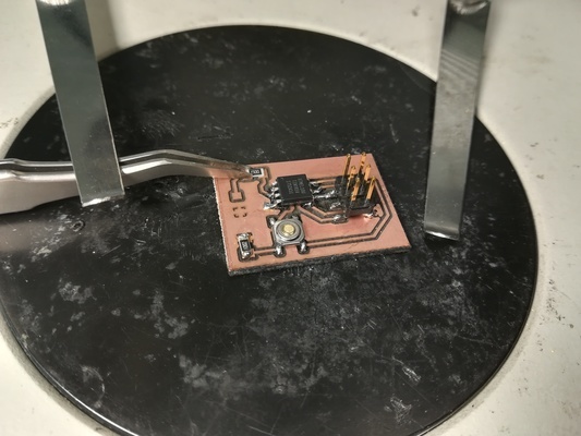
I soldered each component and then make beeping oscilloscope test.
Search for copper hairs
Test it
Programming the board
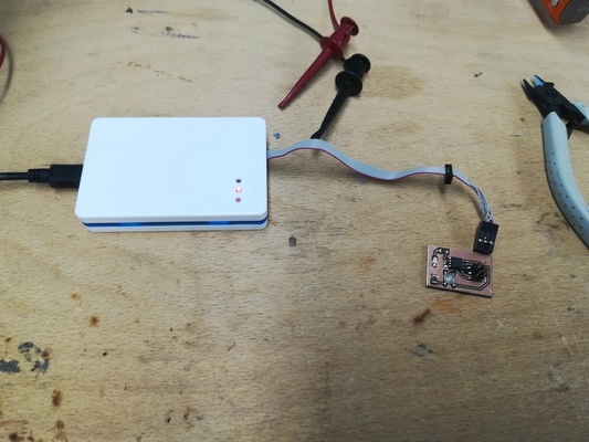
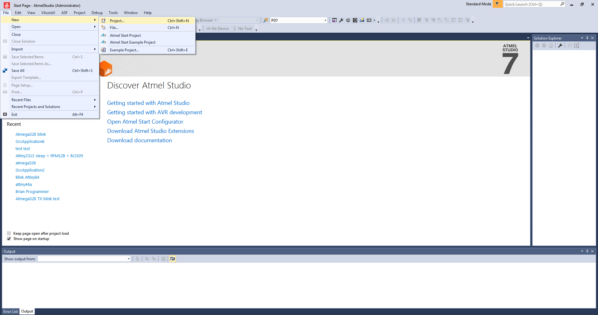
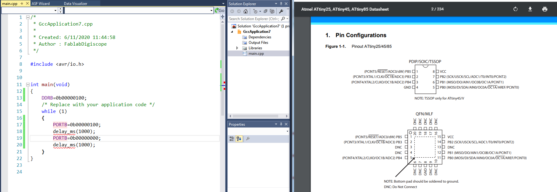
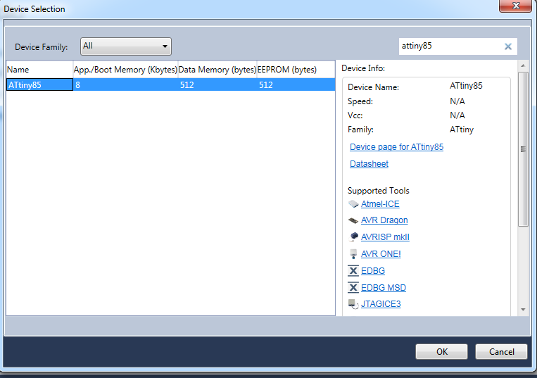
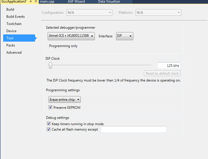
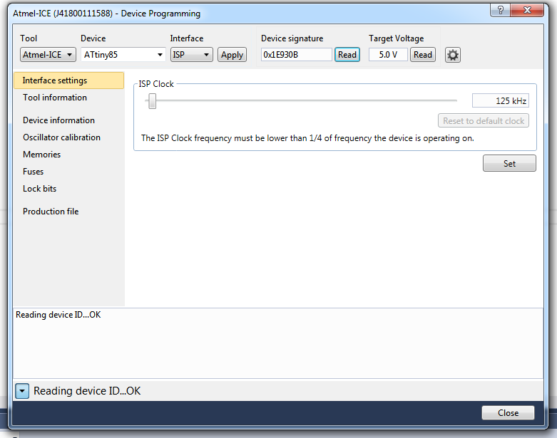
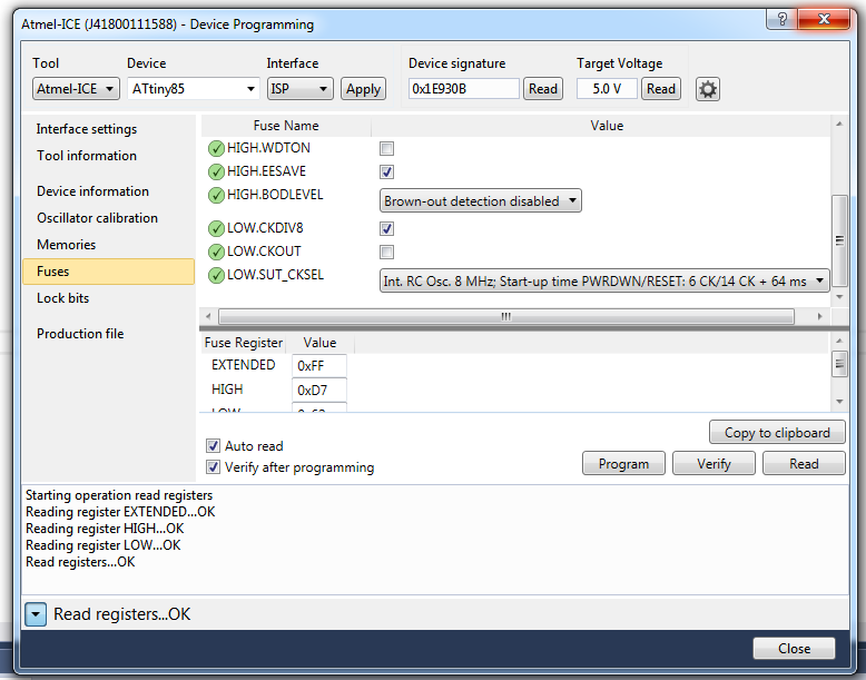
I used ATMEL Studio and ATMEL ICE programmer to program the board.I checked for online documentation of ATtiny45.
I first programmed the board to wait 1 second before turning on or off the LED.
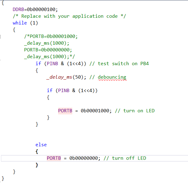
Then I programmed it to turn on the LED
Results
Turn on and off the LED every second
Turn on the LED when the button is pressed
