
BLM

This is a photo of friends and I at a local protest in Charlotte. It was a big part of my week in alot of ways.
Inspiration
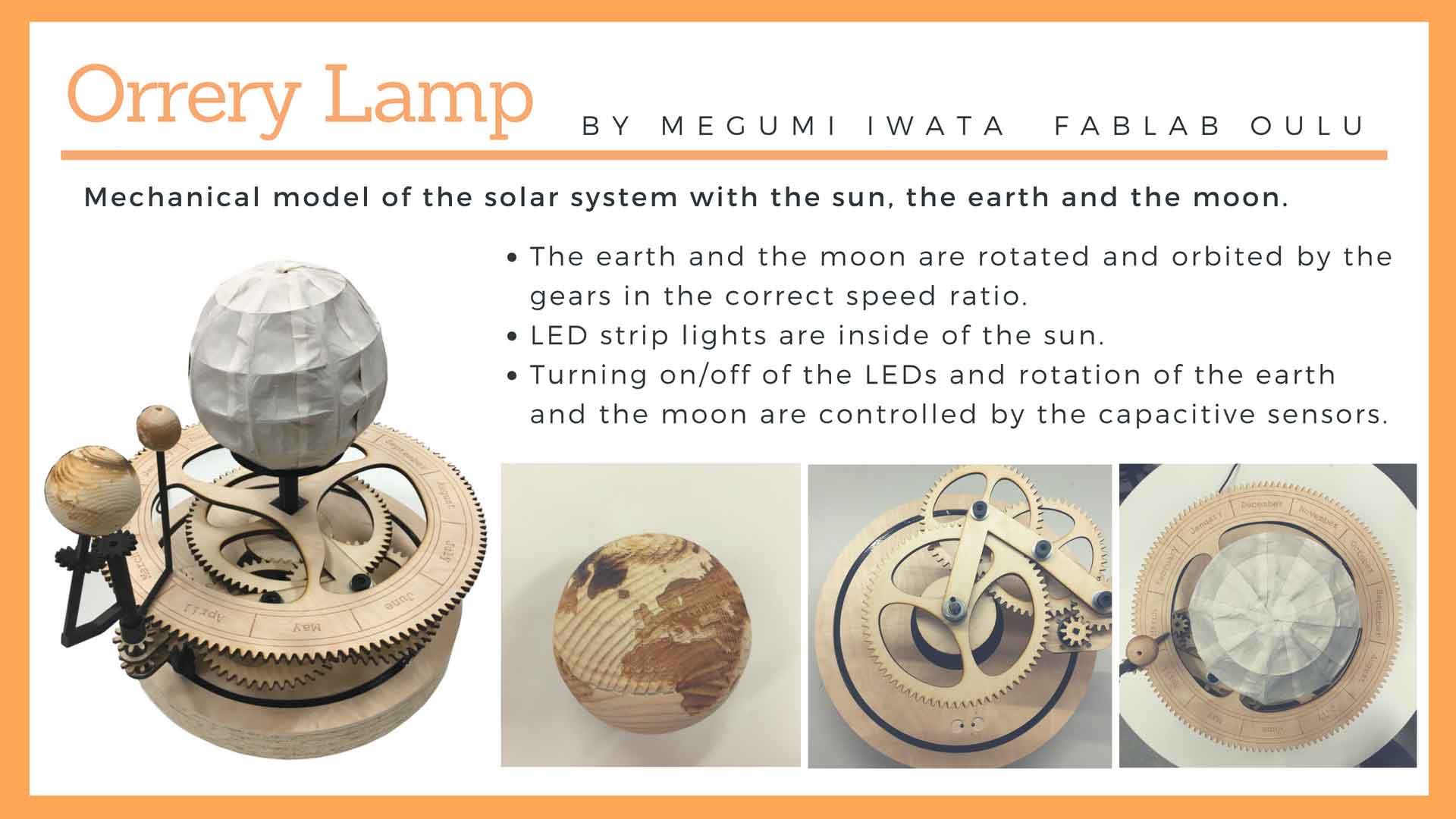
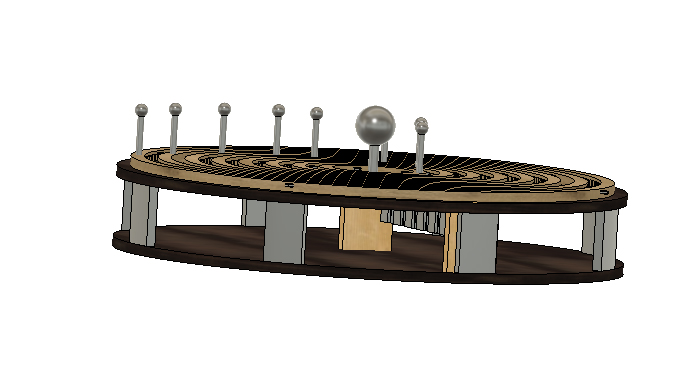
Megumi's Final Project. This project is the final project of a student of the Fab Academy in 2018 and it’s an orrery that can be used as a night lamp controlled by a phone.
This project is simply amazing! This student created from scratch an entire planetarium with over 70 gears. He used a do-it-yourself CNC, fusion 360 and the program gearotic motion to come up with the gears combination.

This project provides valuable information on how to think the mechanical part of the planetarium, and we will work on simplifying the mechanical part by using stepper motors or DC motors. I think that by using 3/4 motors we can reduce the number of gears to less than 20. But still need to work on it. How to Build a Precise Mechanical Planetarium Instructables.
Tasks
We had a discussion on projects that we could bring forward together remotely and we finally ended up choosing to work on a planetarium. This is part of my final project but I figured it would have been too hard for me alone to develop the gears’ system, so I think that working on this project all together will help me to advance with my project and add new features. We shared tasks so that Zina is in charge of the GUI for control system, Spencer is in charge motor controllers and frame, Madison supports the 3D modeling of the gears and I am in charge of researching the gears system and to do some research on existing projects. The gears part has been quite complicated for me since I decided to work on this project as my final project. But I think that with the help of the others we will be able to come up with a great system!
Motor Control
The GUI with communicate with the IC using pyserial. The control scheme depends on which motor we end up using
Stepper Motor Control
Since we all have access to arduinos and a stepper motor from our kits I thought it would be a good idea to base the motor control off of that. for the final motor control we will need to use larger independently powered motors. The advantage of using stepper motors is high positional accuracy built in without any other systems. The major disadvantage is high cost and power consumption.
DC Motor Control with PID
One option is to close the loop and use a dc motor with a pid control to position it. I found some helpful code that was helpful to understanding the control scheme. the primary advantages for this would be lower cost, faster speed, and potentially increased accuracy. The primary disadvantages would be the increased complexity of a hall effect sensor and magnets along the ring.
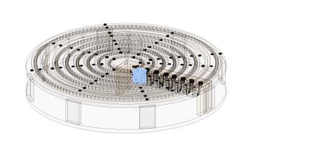
Gantry + Frame
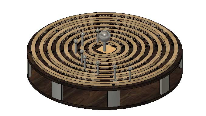
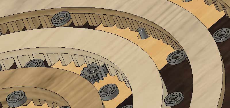
The gantry design was done in fusion 360. The frame will be cut out of two sheets of 3/4 nominal plywood. The gear teeth for the internal gears will need to be cut with a 1/4 inch bit. for generating the gears I used this script to generate the gears, with some modification after the fact. This had some issues and though I was able to adapt it to the drawing it was less than idea.
Creating Gears... CLICK HERE!
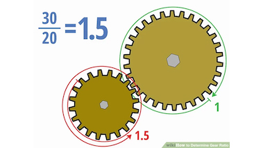
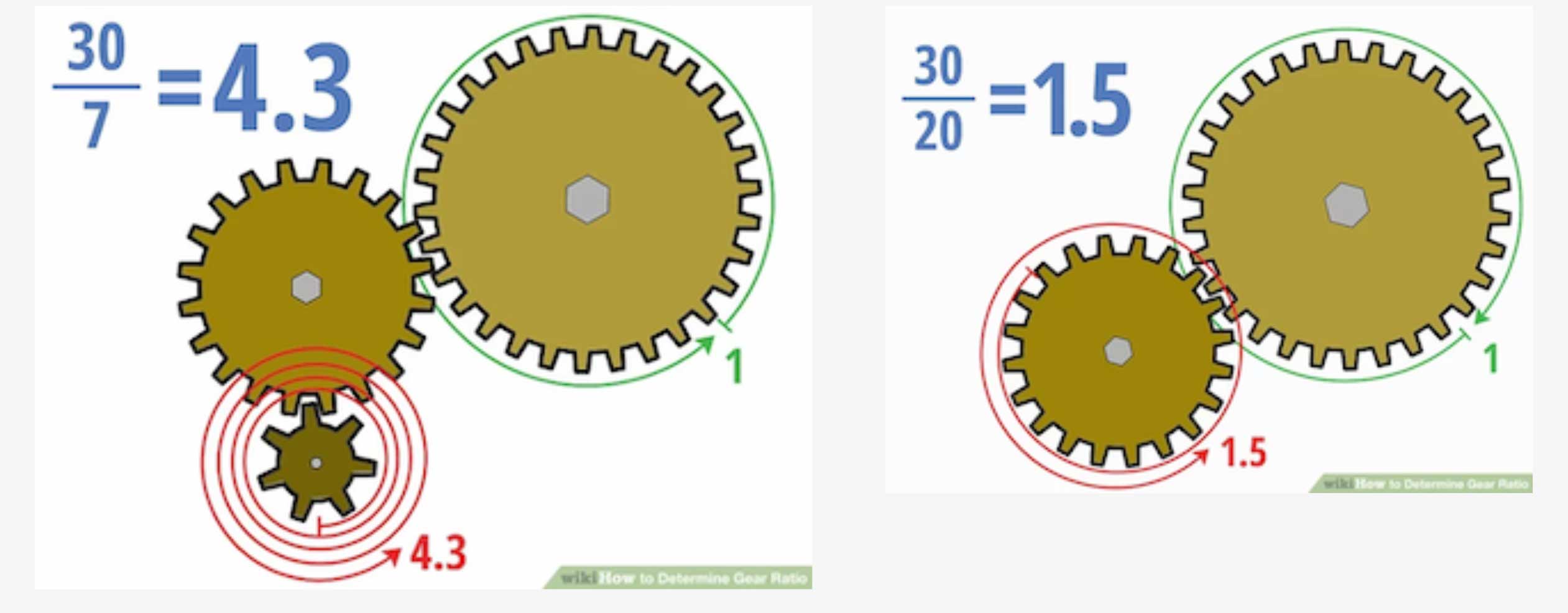
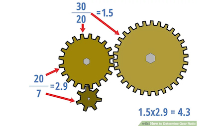
Studying gears is faschinating. The first important concept about gears is the gear ratio. Definition: a gear ratiois a direct measure of the ratio of the rotational speeds of two or more interlocking gears. As a general rule, when dealing with two gears, if the drive gear (the one directly receiving rotational force from the engine, motor, etc.) is bigger than the driven gear, the latter will turn more quickly, and vice versa. We can express this basic concept with the formula Gear ratio = T2/T1, where T1 is the number of teeth on the first gear and T2 is the number of teeth on the second. Therefore, the gear ration shows how many times a gear has to turn for the other one to make an entire turn. A ratio of 1:3 means that a gear of 1 teeth will turn 3 times for each turn of the gear of 3 teeth. So, if we want to create gears for a clock, for example, we need to have a ratio of 1:12 because you need the gears with the minutes to turn 12 times for the gears with the hours to go back to the original position. Now, gears with one tooth are of course not possible and this tutorial suggests to have gears with at least with 7 teeth. So, in the case of the watch, we would have 7:84.
Now there is a problem. A gear of 84 teeth would be pretty big! To avoid making such a big gear, it is possible to use 3 or gears instead of 2 as long as the ratio stays the same. IMPORTANT: The important thing to remember when dealing with gear trains with more than two gears is that only the driver and driven gears (usually the first and last ones) matter. In other words, the idler gears don’t affect the gear ratio of the overall train at all.
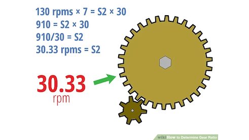
Another important concept for our project is the speed of the gears. We need to identify the final speed of the gear driving the planet by setting the speed of the gear connected to the motor. In case of 2 gears, the calculation is pretty simple. It is enough to use this formula: S1 × T1 = S2 × T2. So, if for example we know that a small gear connected to the motor has a speed of 130 rpm (rotations per minutes) and we know that this gear has 7 teeth and the gear driving the planet has 30 teeth, then the speed of the larger gear would be 130rpm*7:30 = 30.33rpm.
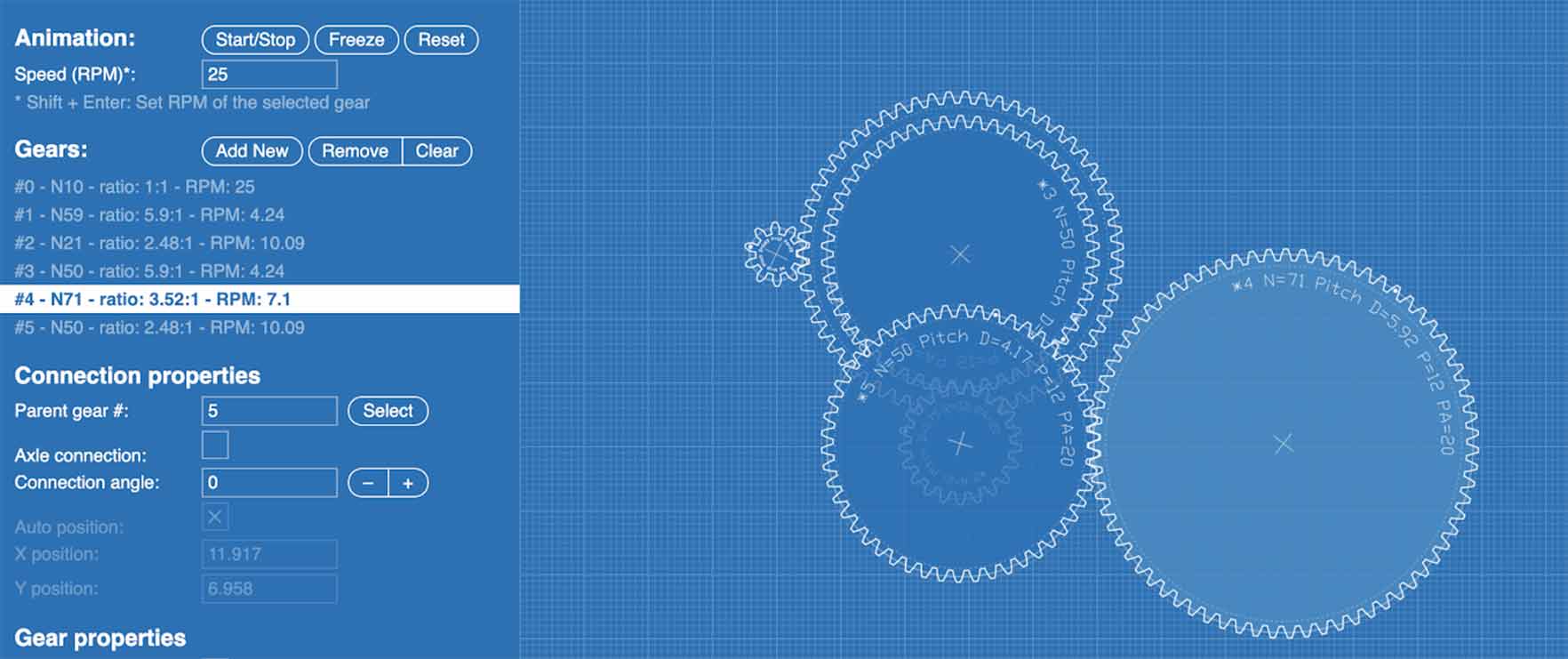
The first option I tested to create the gears is the online gears generator. I watched this tutorial to understand how it works. And I also created the gears for Mercury as a test. Howvere, the online Gear Generator charges 2$ to export an SVG!! Though this isn’t a ton of money, I was grumpy that it wasn’t clear that you needed to pay to export, and we can be paying for svgs!
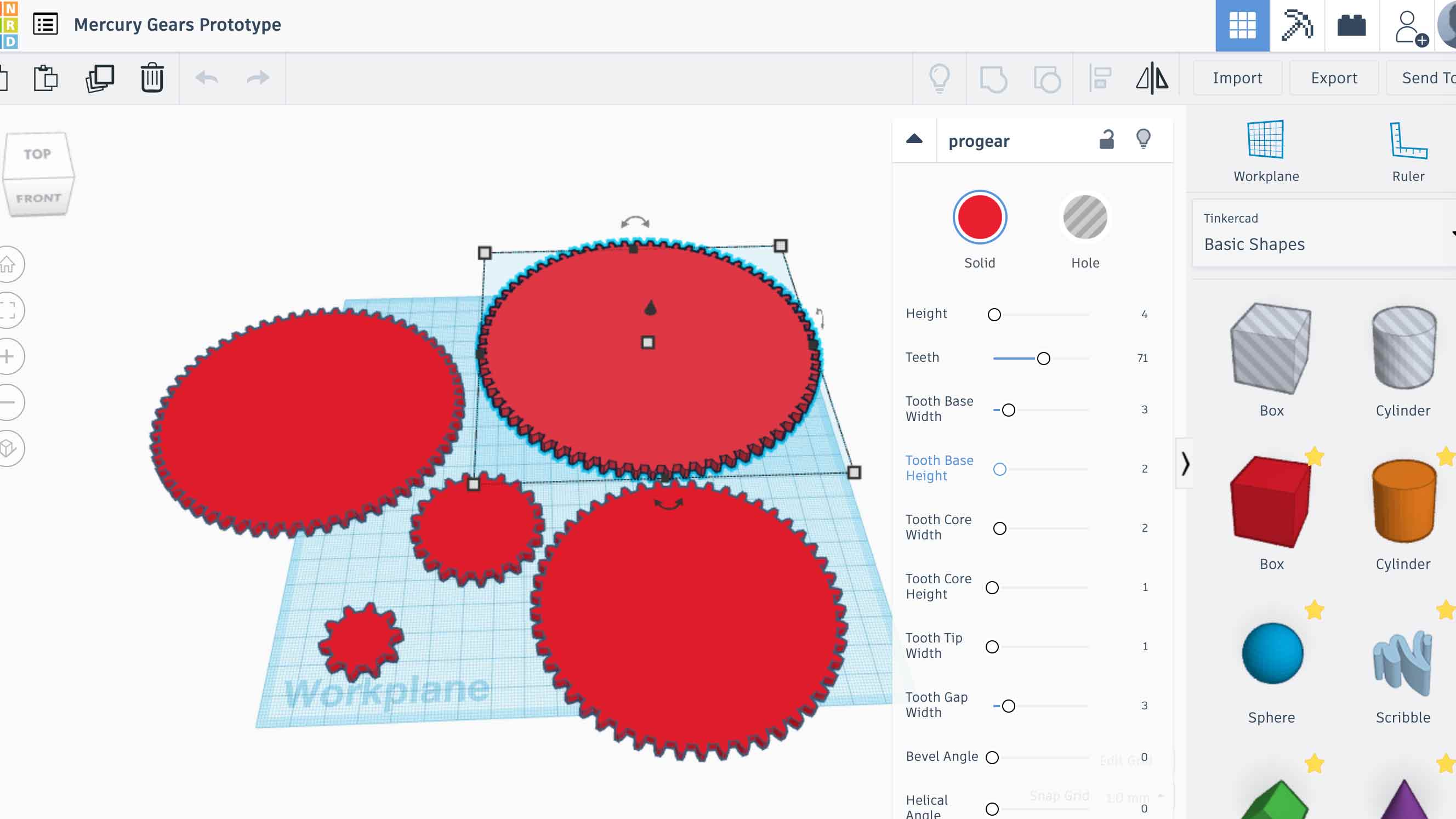
I also had an interesting time looking up how to make gears. There are alot of Youtube videos about how to model gears on Fusion but they are mostly out of date. Out of curiosity and frustration, I checked out Tinkercad to see if they had any good plugins and they had at least four just dedicated to making gears!
As part of the initial research, we found this Instructables which gave us some basic gear ratios to work with. I think we ultimately scrapped the idea of doing this many gears per planet...
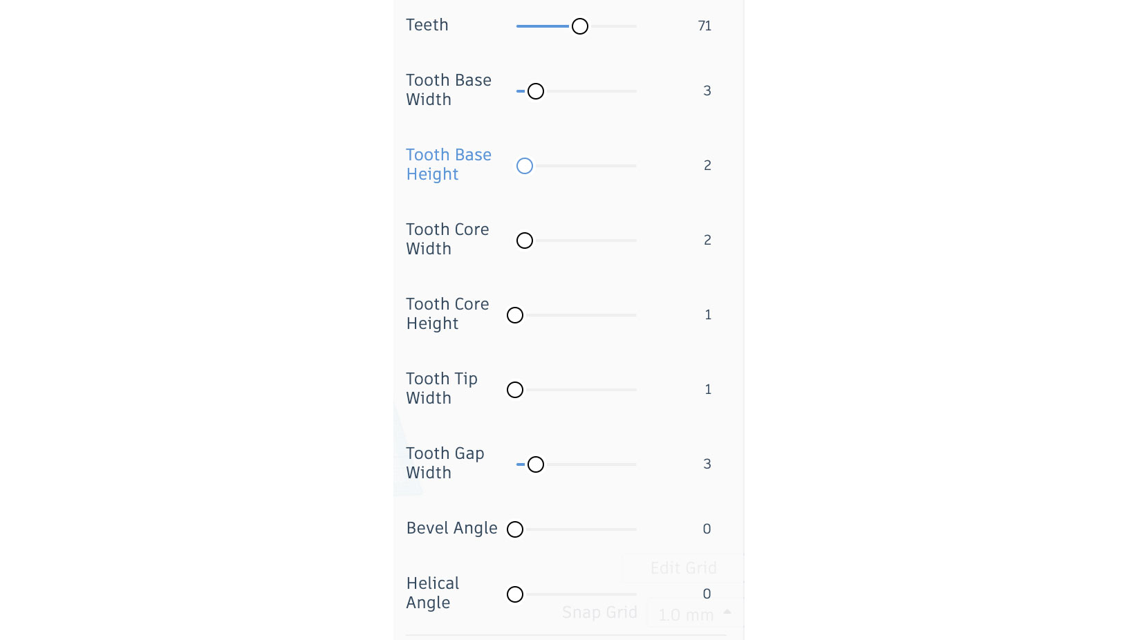
Gear tool I found on Tinkercad.
So which gears system should we use?
OPTION 1
We could use a complex system of gears like the one used in the mechanical planetarium with over 70 gears. In that case, we could replicate the system of gears used in the planetarium project which is the following:
Mercury: 10, 50, 50 / 59, 21, 71 Venus: 11, 92, 29 / 63, 53, 79 Earth: 11, 31, 31 / 79, 23, 85 Mars: 12, 74, 19 / 73, 73, 87 Jupiter: 28, 71 / 92, 39 Saturn: 35, 61 / 92, 39 Uranus: 18, 47 / 92, 83 Neptune: 16, 31 / 89, 86
This of course is not the only combination available. However, I could not find any program like gearotic motion that would work on mac. If I understood well, with that program you can set the ratio you need and the program suggests a gears system that would work. I also found this alternative algorithm developed in R for a similar project:
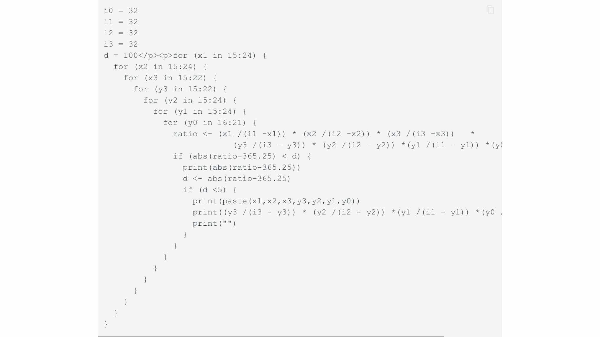
However, I can’t use R and it’s too time-consuming in this week to try to figure out how to use this program. More generally, the gears systems developed in this way are very VERY complex for me.
OPTION 2
Alternatively, we could use a simpler system with motors for each planet. That would save us quite a lot of headaches to figure our the gears system. In this case, we would need 2 gears for each planet. One connected to the motor and one connected to the ring of each planet. Something like this system used for a clock:

The motors are drawn as NEMA 23 stepper motors, ideally in the final project we will adapt it to use fewer motors with a gear box between them.
The bearings along the frame hold the rings in position along the side. Experiments are needed to see what is needed for a bushing along the bottom. I hope that a simple low friction hdpe block will allow for easy movement. Another option is to add ball bearings to make the rings into large roller bearings.
Useful Resources
mccmaster carr into fusion 360
Make a Tellurion (sun-earth-moon Orrery) for Your Kid
Solar System Orrery (3D Printed)
Stay 6 feet apart!
In a typical year, I realize our group would come together and make this machine that we have created on our screens! But for now, we are still not permitted to be more than 6 ' close to one another and even if we were, our entire group is in a different part of the world. So due to this fact of life right now, it was impossible to work as a team and unrealistic to expect each of us to complete this on our own. I did ask my instructors about this and they checked with coordination thar tis is acceptable given the circumstances.