Assigment #7
Computer controlled cut
The 8th assignment of the Fabacademy it’s about computer controlled machining. For this assignment we have to design and build “something big”, using a big CNC milling machine.
1 – a fence holder.
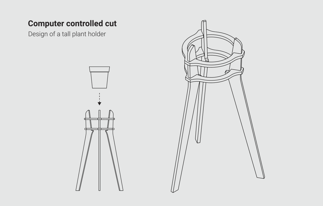
Putting together toxic fumes from the lasercutters, micro powders from cnc milling machines and fumes from electronic soldering, we can say that Fabbers canexpect a very shor life… To fix this I’m going to build a support for a fence, which is a plant that has a very powerfyl capacity of absorbing toxic fumes and provide fresh oxigen. To make my plant holder I will design a 3 legs piece of furniture kept together by 2 rings. The vase will be placed in the middle of the element, and by keeping the legs pushed towards the rings will be actively part of the structure
2 – Parametric 3d modeling in freecad
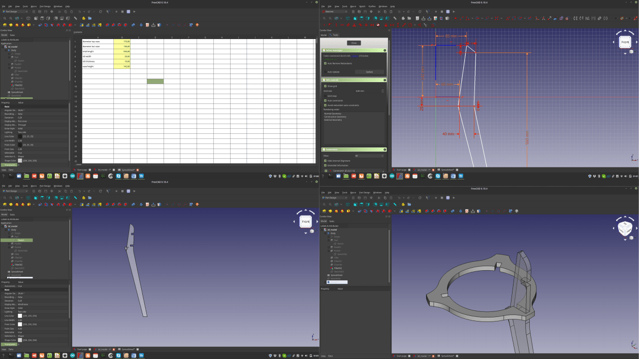
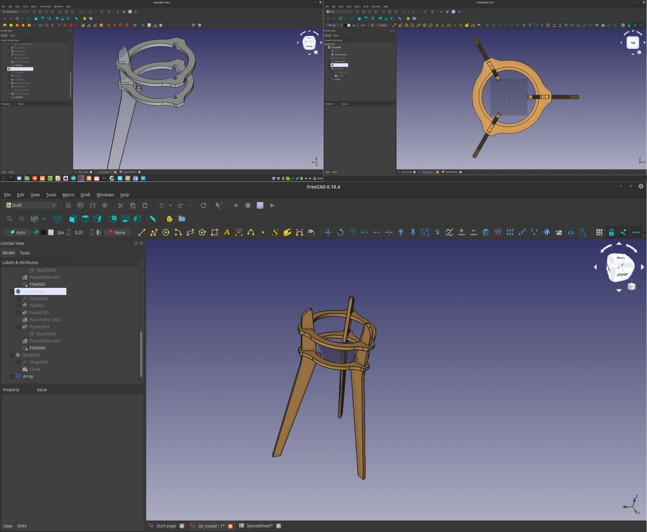
Top design the object I started with creating a spreadsheet with all the measurements I will use in my 3d model. Then I moved to the Part design workbench to design the first leg (using the sketch > pad) command, and then the same commands to generate the rings. As a final thing I made a circular array of the legs replicate them and have 3 of them
3 – CAM
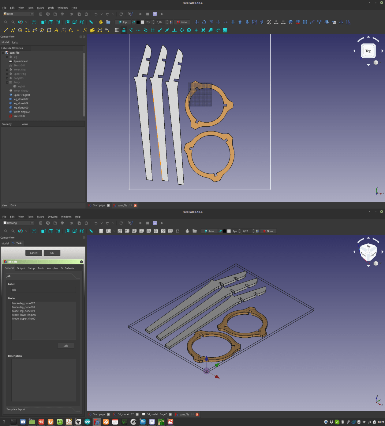
Once I was happy with my design I had to placed all the parts on the XY plane using the deaft workbench, and switched to the Path workbench.
The path workbench allows you to generate a paths around your shapes, and then export them in G-code and operate a cnc milling machine to build them.
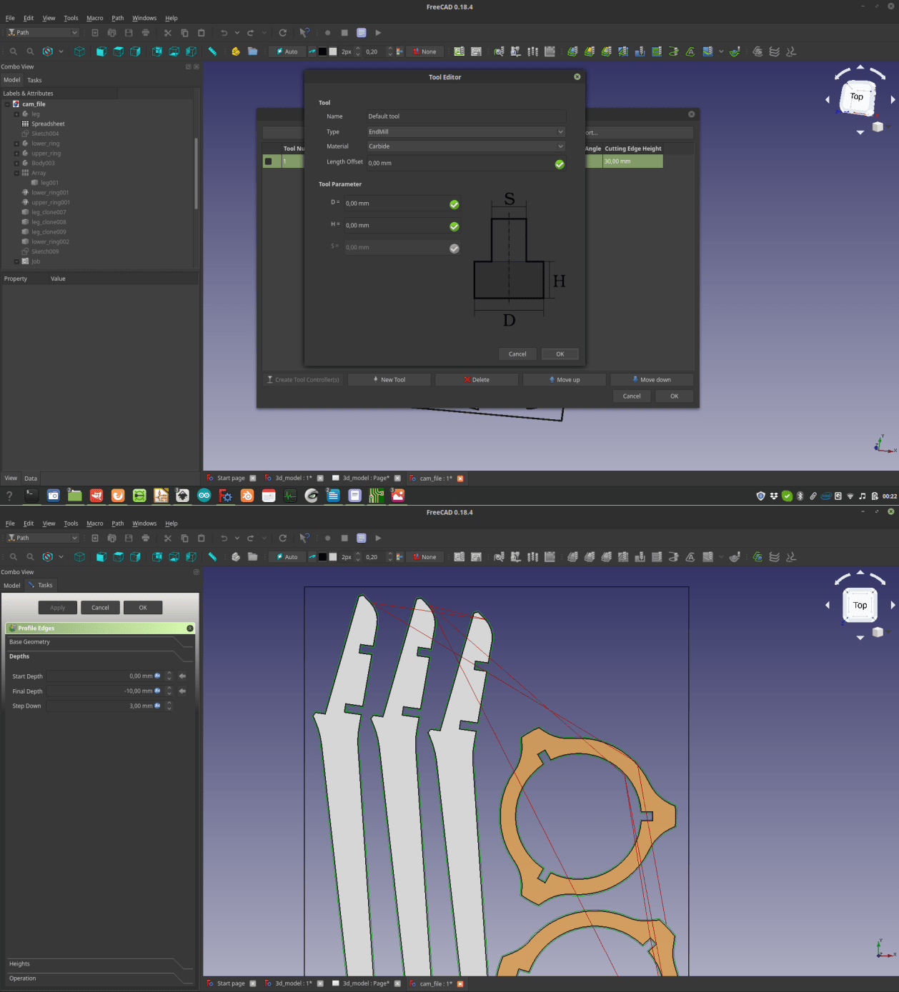
The first step it’s to create a so called “Job”, declaring the dimensions of the piece of wood you’ll be using.
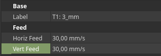
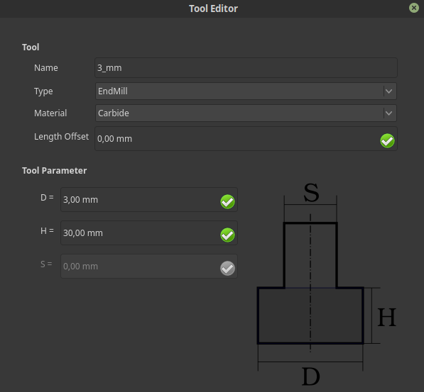
Then it’s time to work with your “tools library”, which is where you add the bit(s) you’ll be using to mill your pieces, in my case it’s a flat 3 mm bit.
You also need to declare the feed and the jog, this can be done using the left side “data” menù
 Next step it’s to instruct the CAM software to generate the paths, in my case I used a contour path for base object for the outer borders, and a profile based on edges for the inside of the rings.
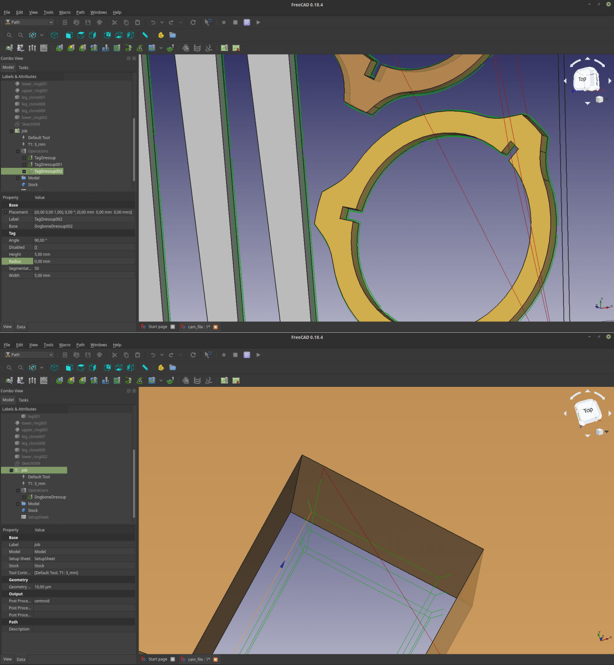
The paths were then generated, but I needed to add a dogbone dressing for the connections, and a few tabs to make sure my objects wont fly away while I mill them.
To do that you need to navigate to the “path dressup” menu, and add and edit your features.
Once everything it’s done I just selected my job and exported it as Gcode, using “LinuxCNC” as a post-processor, which is compatible with UCCNC (the driver I’ll be using with the machine).
So, to summarise the setup of my job, I'm using a flat 3mm 2 flute bit, with a feed of 30mm/s, the stepover will me 3mm (like the diameter of my tool), and the spindle will be spinning at 10000 (this last setting will be activated by manually turning a knob placed on the spindle itself)
Next step it’s to instruct the CAM software to generate the paths, in my case I used a contour path for base object for the outer borders, and a profile based on edges for the inside of the rings.
The paths were then generated, but I needed to add a dogbone dressing for the connections, and a few tabs to make sure my objects wont fly away while I mill them.
To do that you need to navigate to the “path dressup” menu, and add and edit your features.
Once everything it’s done I just selected my job and exported it as Gcode, using “LinuxCNC” as a post-processor, which is compatible with UCCNC (the driver I’ll be using with the machine).
So, to summarise the setup of my job, I'm using a flat 3mm 2 flute bit, with a feed of 30mm/s, the stepover will me 3mm (like the diameter of my tool), and the spindle will be spinning at 10000 (this last setting will be activated by manually turning a knob placed on the spindle itself)
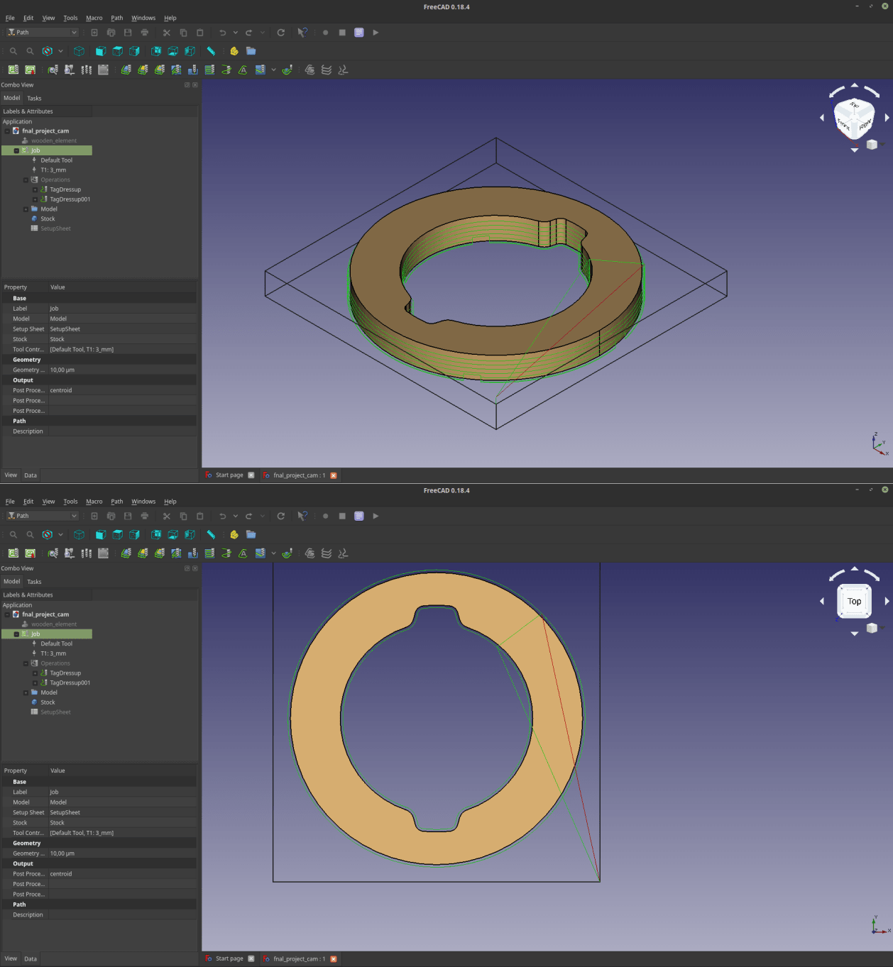
 Before moving to the actual machine I used the simulation function of the software, so that I could double check if all the settings were correct.
cam_simulation_plant_holder from Chi Ha Ucciso Il Conte on Vimeo.
3 – CAM for final project
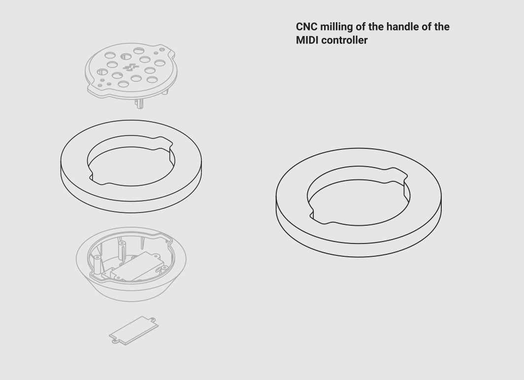
Together with the furniture element asked by Neil I also decided to cut an element that I’ll use for my MIDI controller.
So, I moved back to the CAD 3d model and did the same steps to instruct the machine to cut tha circular element that will be tha handle of my conroller (I’m really into circular shapes lately…)
The functions I used were nearly the same I used for the plant holder.
Screencast 2020-03-14 010104 from Chi Ha Ucciso Il Conte on Vimeo.
4 - Cuttng my pieces
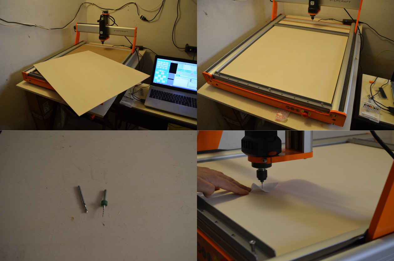
Since we are in the middle of the Co-vid 19 pandemic, access to the lab is quite limited, but I finally managed to get in there for a few hours and get my CNC work done. The machine I'll be using it's a Stepcraft 2/840. The first thing I did was to attach the wood to the sacrificial layers, then I set up the origin of my cut, and finally started to cut (all this using the machine's driver which is UCCNC). The cut went quite smoothly, and at the end of the job I just had to remove the pieces and using some sand-paper to smooth the edges of the elements
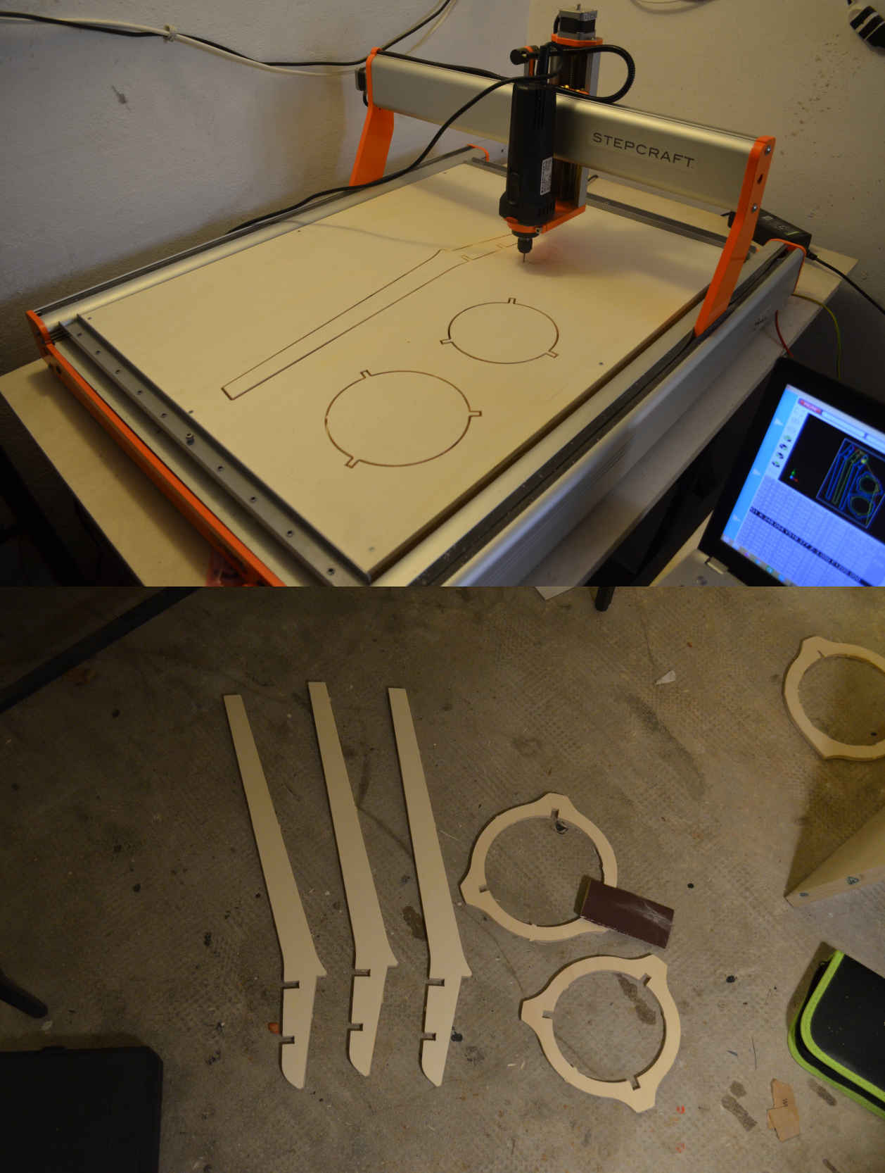
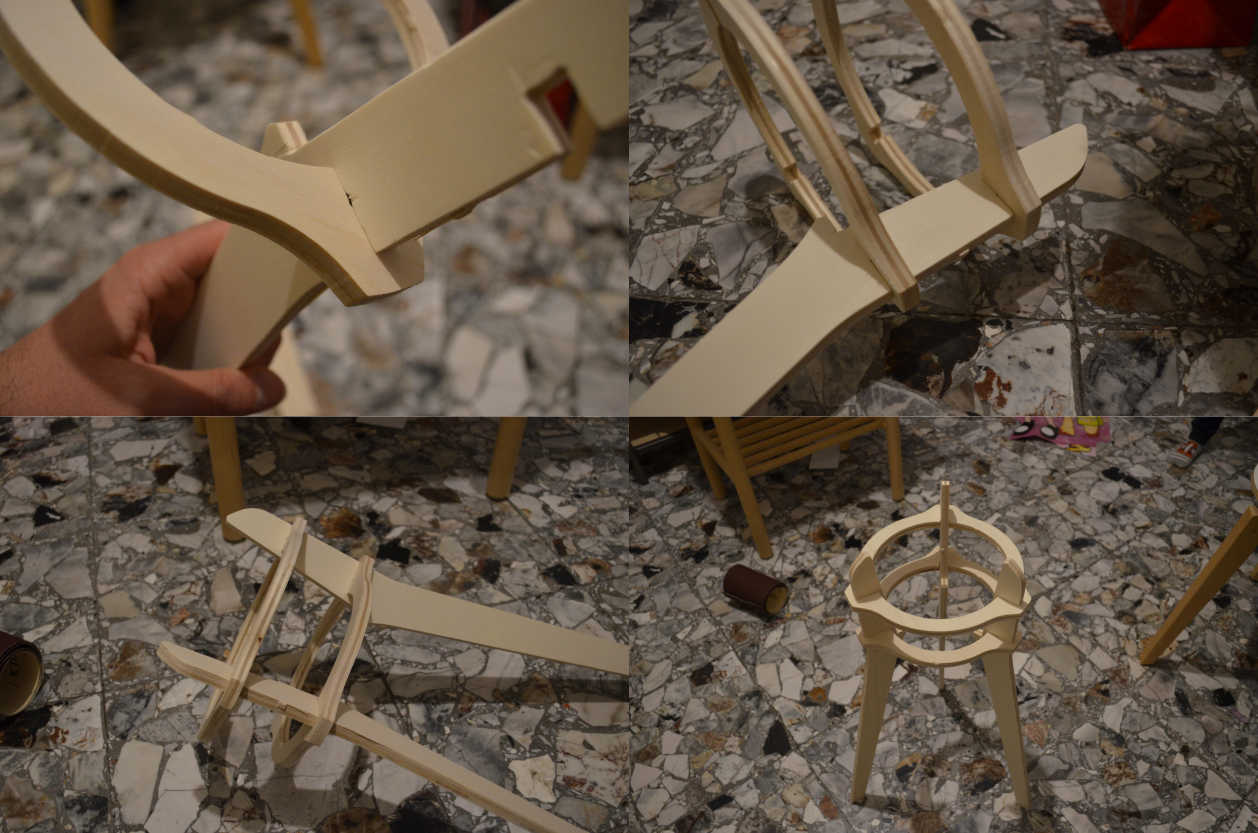
5 - Assembly
Last part of the plant holder building was to assemble it.
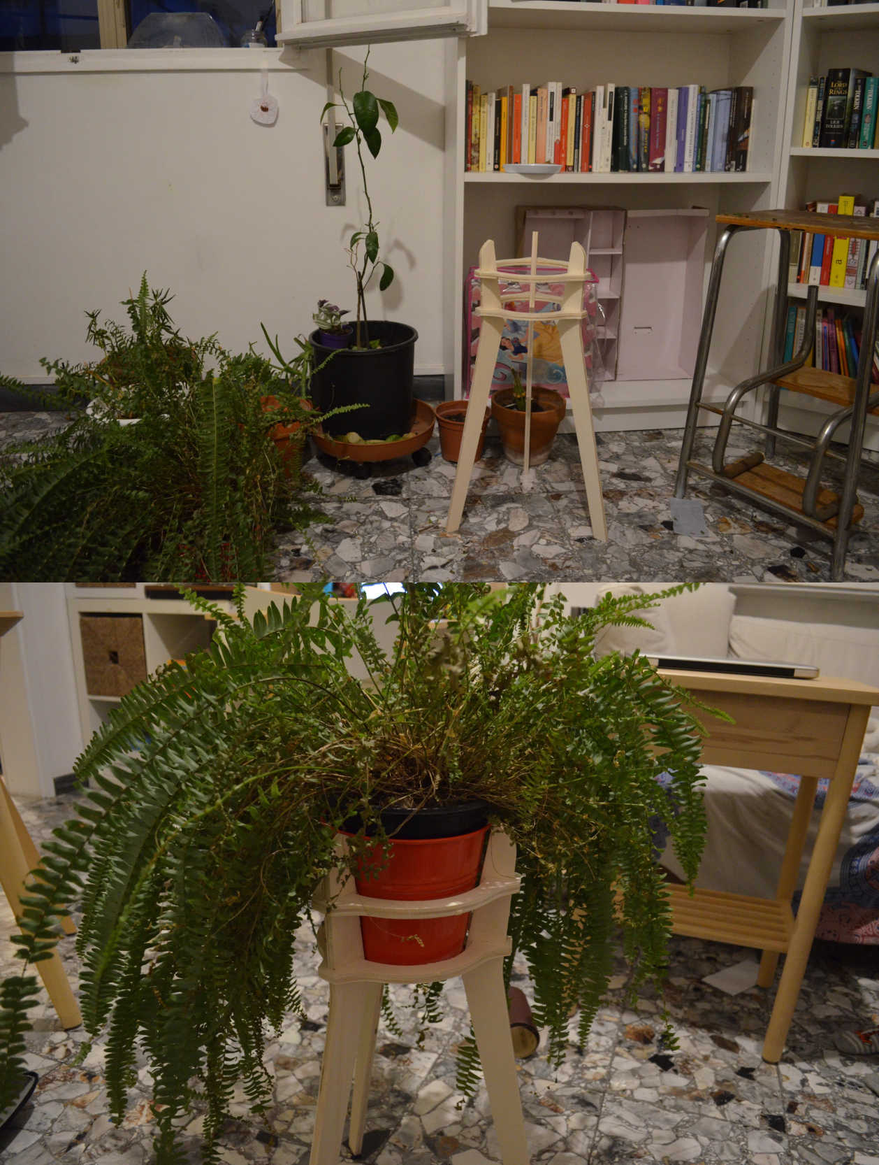
I designed the connections to fit perfectly, and the result was as expected:
The parts are easy enough to put together and they stay in place firmly. On top of that, the vase prevents the legs of the holder to move backward, and the piece it's therefore very steady.
I'm really happy with how this assignment went.
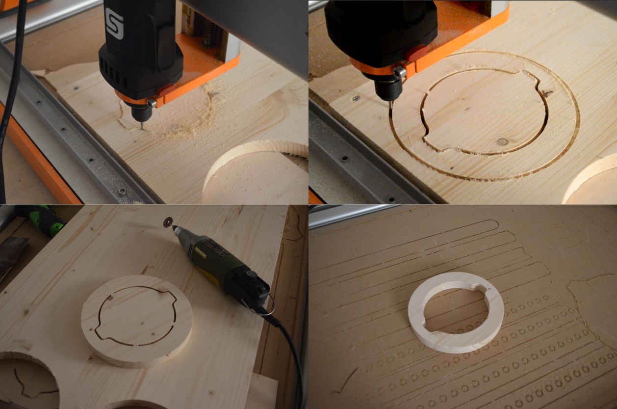
6 – Milling final project wooden element
After my plant holder, I went for the wooden element of my final project.
The piece I’m going to mill is a circular element that will function as a handle for my final project, The part will be milled out of a very nice piece of fir wood.
Just like I did for the assignment, I first set up the origin of the milling work, and then I sent the job to the machine, then I removed the tabs with a Proxxon and used some sanding paper to smooth it.
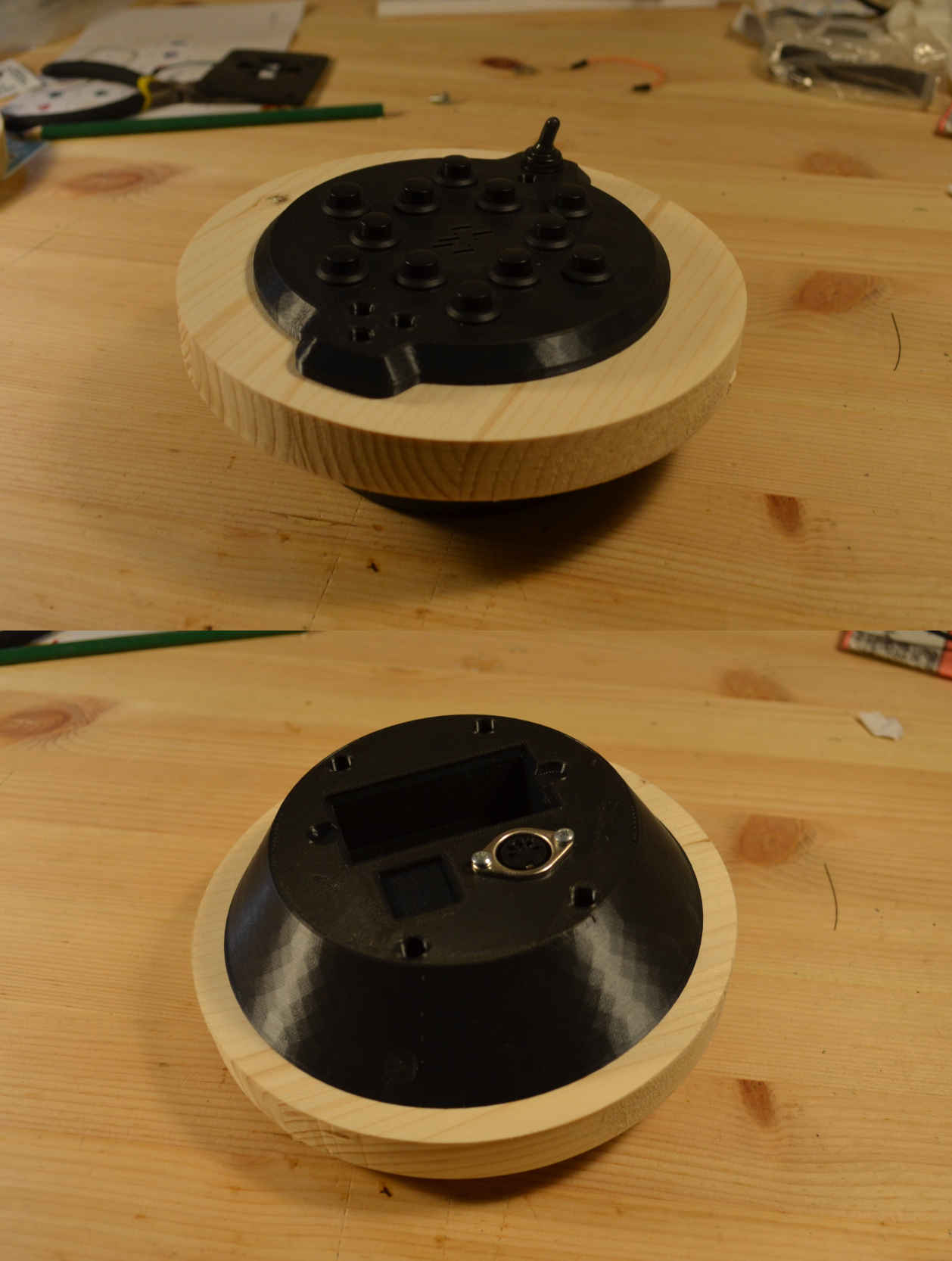
7 – assembly test for final project wooden element
The 3d printed shells perfectly fitted with the wooden element, and once it’s secured with screws it’s very firm and steady. I like very much the combination between the black plastic and the wooden element. I might try to color the wood before applying protective paint on it.
source files
Here are all the source files for the Electronics Design assignment:
1 – Plant holder 3D model
2 – Plant holder CAM
3 - Final project CAM