Assignment 13
Networking and Communications
group assignment:
send a message between two projects
https://fabacademy.org/2022/labs/ciudadmexico/embedded-networking-and-communications.html
individual assignment:
design, build, and connect wired or wireless node(s)
with network or bus addresses
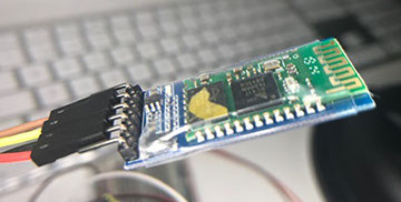
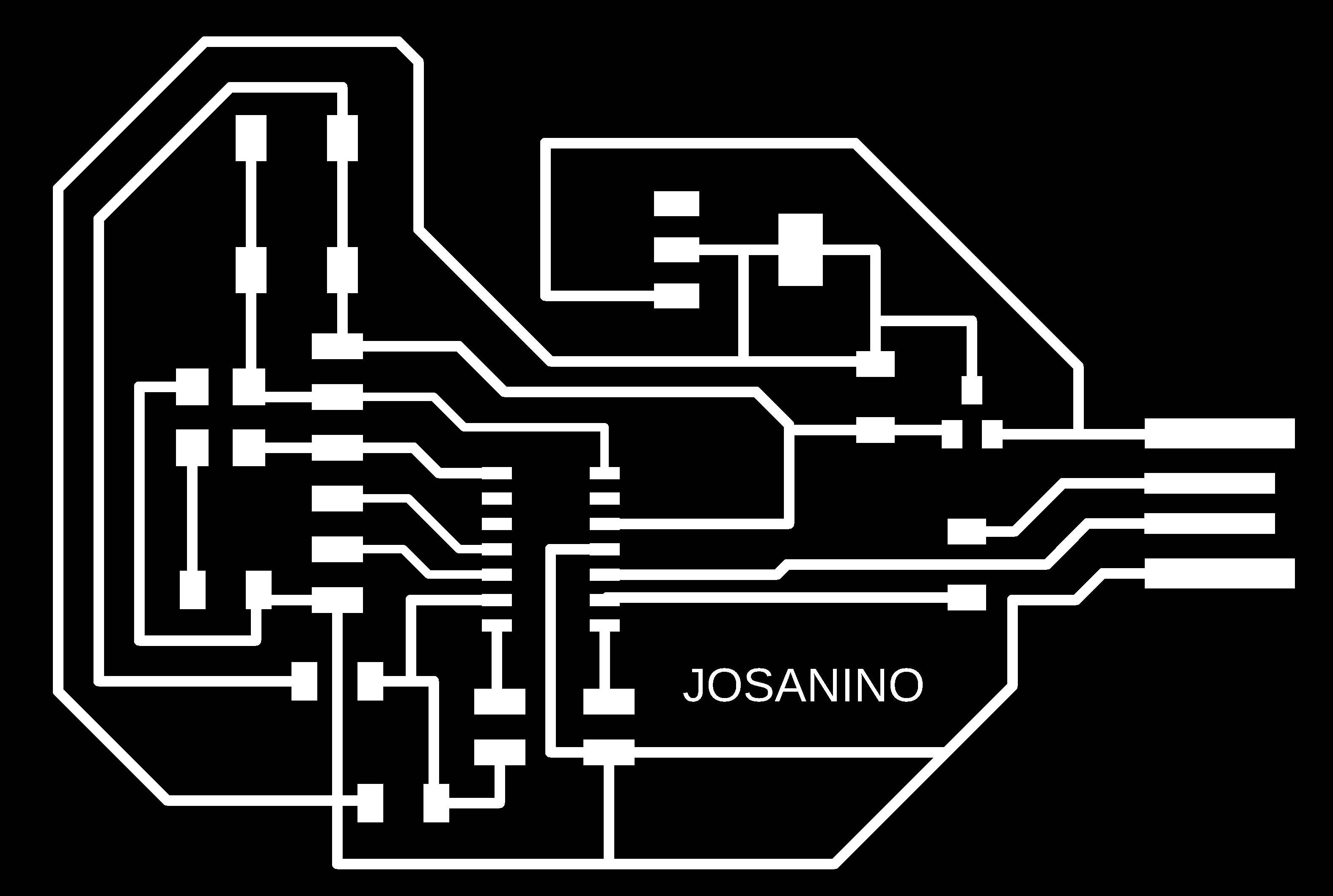
For this work I designed a card based on my original Josanino but I included a button and a led in addition to connecting the Atmel processor to the Two Wire Interface (TWI ) pins or also known as I2C which would be SDA (PA14) and SCL (PA15). Said pins are digital and will also help us to connect and program it with another card
The I2C is an inter-integrated controller. This is a serial communication protocol that can connect low-speed devices. It is a master-slave communication in which we can connect and control multiple secondaries from a single master. The I2C bus transmits data and clock with SDA and SCL.
For more specific information about I2C you can consult the following links
https://www.i2c-bus.org/i2c-primer/how-i2c-hardware-works/
https://content.arduino.cc/assets/Nano-Every_USB-Serial_Atmel-42363-SAM-D11_Datasheet.pdf
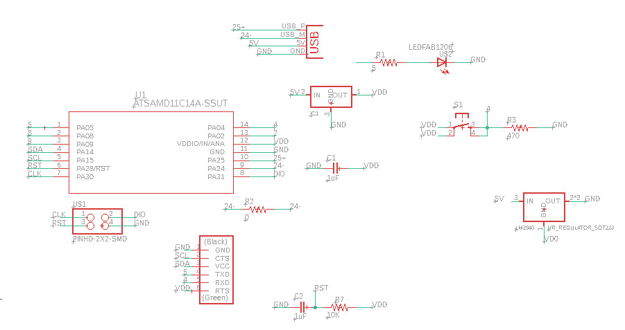
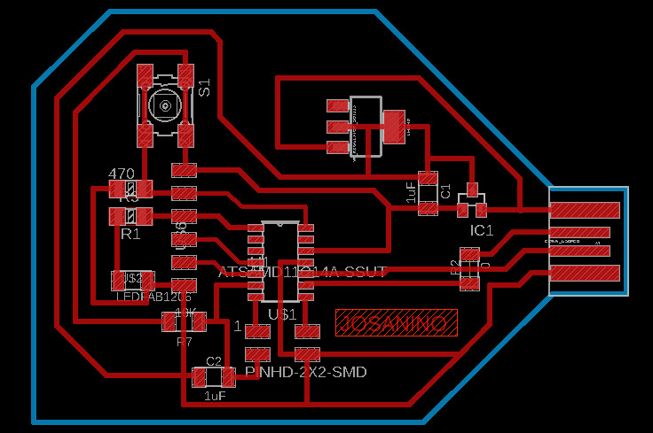
The schematic and the board are made in the eagle software


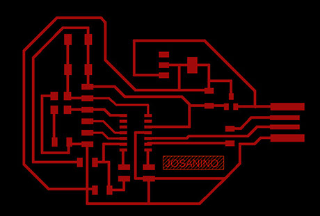
We export from eagle the image with .PNG format and in monochrome at 1200 dpi and with the window option where the origin 0,0 will be the lower left corner
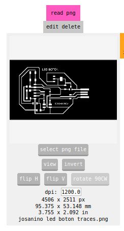
We export from eagle the image with .PNG format and in monochrome at 1200 dpi and with the window option where the origin 0,0 will be the lower left corner. We open it in the mods software
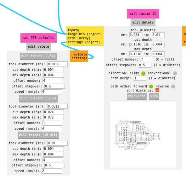
We select the mill traces button (1/64) to assign the cutter that will trace the tracks, we also assign the number 4 to the offset and the speed also in 4 so that the traces are milled without breaking.
Later we press the calculate button so that the machine calculates the route to be made on the copper plate of our PCB
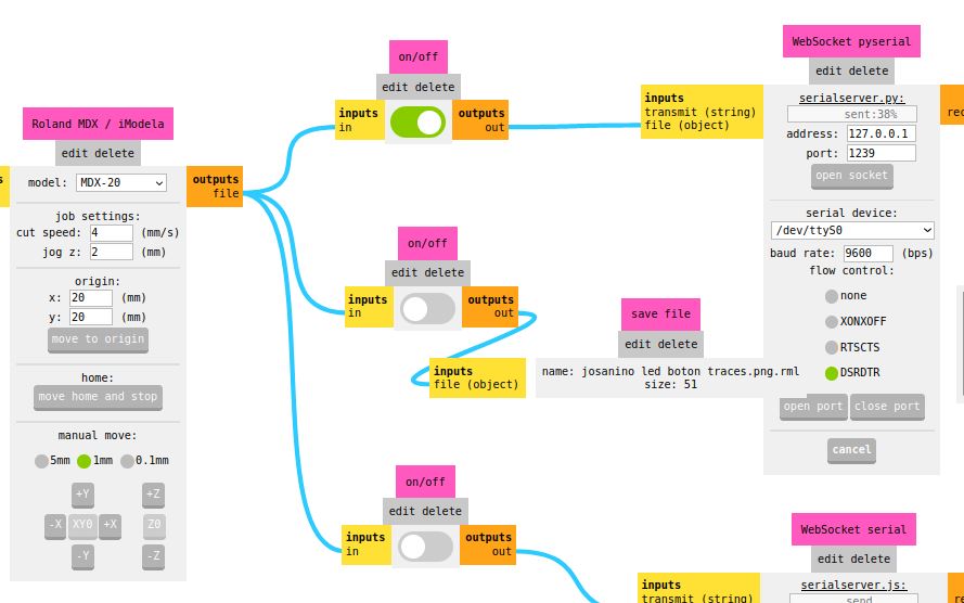
We verify that the MDX 20 model machine is selected and we assign the origin right at the corner of our plate placed on the machine, which in this case was the coordinate x=20 y=20. We turn on the first button and press the open port button so that the machine makes the correct connection to machine the PCB board.
Plate milling
-crop-u41648.jpg?crc=58615230)
Plate milling
-crop-u41640.jpg?crc=246459726)
Plate milling
-crop-u41689.jpg?crc=4241718729)
.jpg?crc=3825993986)
.jpg?crc=173720422)
Once our plate is cut, all the overlapping components are presented to verify that no component is missing and start welding
Welding electronic components
-crop-u41675.jpg?crc=282422988)
Welding electronic components
-crop-u41682.jpg?crc=245817113)
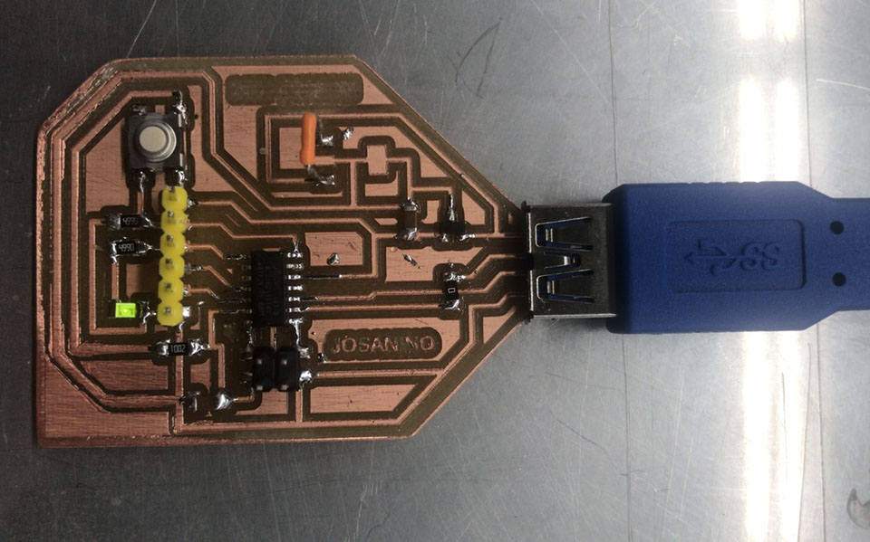
Board ready and with all the components already soldered
Button
-crop-u41740.jpg?crc=314763608)
Resistor 499.0 OHMS
Capacitor 10 uF
Regulador 3.3 -0.1 A
LED Red
AT SMAD IIC
Header
Resistor 0 OHMS
Resistor 10k OHMS
jumper
Capacitor 10 uF
Programmable header for our card
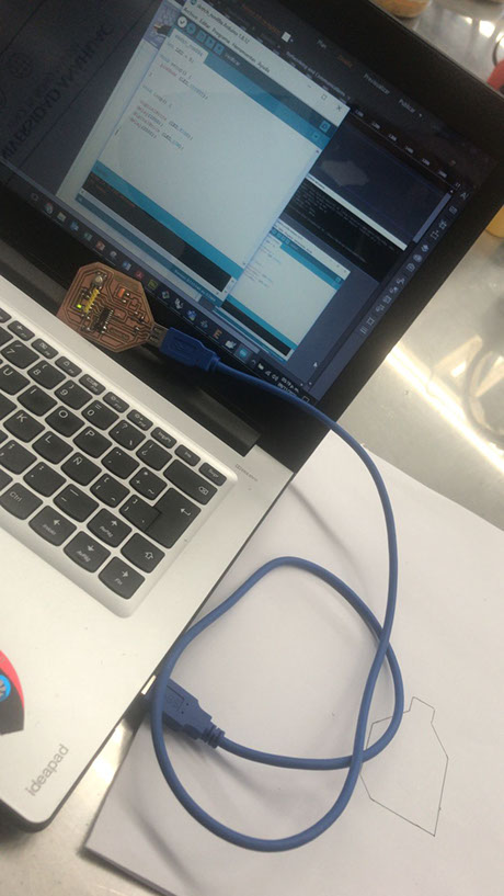
Once the pcb is ready with all the components, we program it with the help of another board and the Command Prompt program (Símbolo del sistema)
We locate in our system the EDBG folder
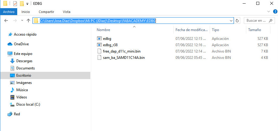
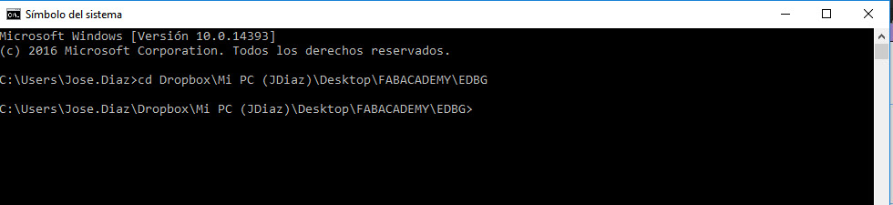
We change directory using cd space and then paste the address of the folder:
Dropbox\Mi PC (JDiaz)\Desktop\FABACADEMY\EDBG
We add the code we got from Adrian Torres' page at FAbLab Leon:
https://fabacademy.org/2020/labs/leon/students/adrian-torres/samdino.html#swd
Comando: edbg -ebpv -t samd11 -f sam_ba_SAMD11C14A.bin
NOTE: edbg It has to be the name of the program as it is in the folder (*.exe)
C:\Users\Jose.Diaz\Dropbox\Mi PC (JDiaz)\Desktop\FABACADEMY\EDBG>edbg -ebpv -t samd11 -f sam_ba_SAMD11C14A.bin
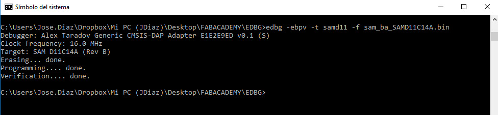
And everything is correct both programming and verification
int LED = 5;
void setup() {
pinMode (LED,OUTPUT);
}
void loop() {
digitalWrite (LED,HIGH);
delay(1000);
digitalWrite (LED,LOW);
delay(2000);
}
Once the PCB has been programmed, we upload the LED test as a check that the card works correctly.

We open the arduino software and in the tools menu we select the port with which it recognized our card COM13 (MattaiTech Xeno Mini)
The PCB designed by me was used as Master and another PCB from FABLAB as Secondary. In the arduino software, the programming of each of them is loaded and activated with the Serial Monitor. In this case, a boozer with the letter A is turned on and off with the letter S.
Master
#include <Wire.h> // Include the networking library.
//char c;
int led = 5;
void setup()
{
Serial.begin(115200); // Open the serial port
Wire.begin(); // It is not necessary to declare an address for the main board.
pinMode(4, OUTPUT); // This is the main board output.
pinMode(led, OUTPUT);
}
void loop()
{
digitalWrite(led, HIGH);
while (Serial.available())
{
char c = Serial.read(); // Read the character written through the serial monitor.
if (c == 'A')
{
//digitalWrite(led, HIGH);
Wire.beginTransmission(2); // This is a secondary board with address 2.
Wire.write('A');
Wire.endTransmission();
Serial.println("writing to address 2!");
}
if (c == 'S')
{
//digitalWrite(led, LOW);
Wire.beginTransmission(2); // This is a secondary board with address 2.
Wire.write('S');
Wire.endTransmission();
Serial.println("stop to address 2!");
}
}
}
Secondary
#include <Wire.h> // This is the library we will be using to allow the board to understand networking instructions.
byte own_address = 2; // This is the address assigned to the board, it will be used to differentiate it from the other boards.
int i = 0;
void setup()
{
Serial.begin(115200);
Wire.begin(own_address); // Declare that this is the board called by a certain address.
Wire.onReceive(receiveEvent); // Instruct what to do when receiving information.
pinMode(4, OUTPUT); //
pinMode(2, OUTPUT);
//digitalWrite(4, LOW); //
//digitalWrite(2, HIGH); //
}
void loop()
{
}
void receiveEvent(int howMany) // What to do when receiving information.
{
while (Wire.available()) // While it is being called.
{
char c = Wire.read(); // Read the character sent by the main board.
if(c == 'A') //
{
digitalWrite(2, HIGH);
i = 0;
do
{
digitalWrite(4, HIGH);
delay(500);
digitalWrite(4, LOW);
delay(500);
i++;
} while (i < 10);;
}
if (c == 'S')
{
digitalWrite(2, LOW);
}
}
}
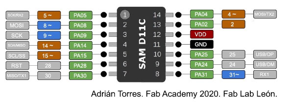
With the help of this scheme by Adrian Torres, we identify and confirm the pin where our LED is connected, which this time is Pin5
Programming is done, we verify it, upload it and execute
int LED = 5;
void setup() {
pinMode (LED,OUTPUT);
}
void loop() {
digitalWrite (LED,HIGH);
delay(1000);
digitalWrite (LED,LOW);
delay(2000);
}

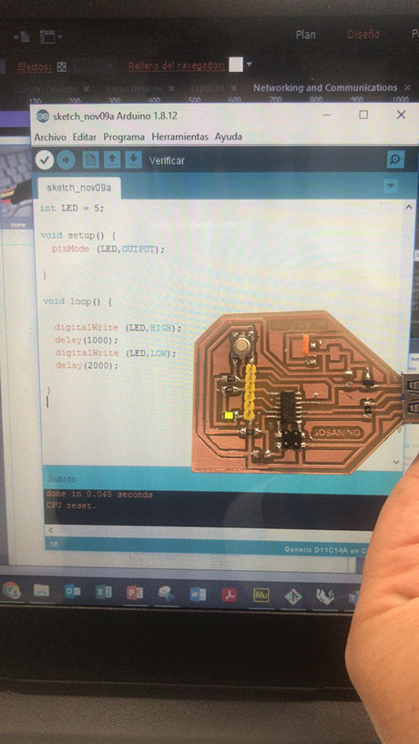

The program is executed correctly since, as indicated by the programming, the LED turns on and off after a few seconds