


Assignment 14
Interface and Application Programming
group assignment:
compare as many tool options as possible
https://fabacademy.org/2022/labs/ciudadmexico/cdmx_interface-and-application-programming.html
individual assignment:
write an application that interfaces a user with an
input &/or output device that you made
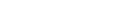
With the help of this scheme by Adrian Torres, we identify and confirm the pin where our LED is connected, which this time is Pin5
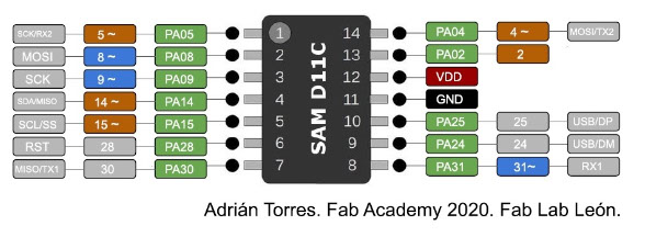
int ledPin = 5;
boolean on = false;
void setup() {
Serial.begin(115200);
pinMode(ledPin, OUTPUT);
}
void loop() {
while (Serial.available()) {
char c = Serial.read();
if (c == 'H') {
digitalWrite(ledPin, HIGH);
}
if (c == 'L') {
digitalWrite(ledPin, LOW);
}
}
}
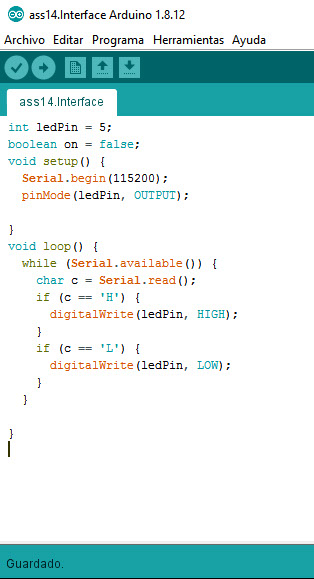
For this purpose, a connection from the computer to our board was made, using the arduino software and the processing software to load the codes. Basically it is to create a figure like the box in which it contains a circle and every time we pass the cursor over the small box it changes color and turns on the LED of our PCB Board.
The serial writing programming of the processing software was taken as a base and the shape, the frame, the colors were modified
import processing.serial.*;
Serial myPort;
int val;
void setup()
{
size(500, 200);
String portName = Serial.list()[0];
myPort = new Serial(this, portName, 115200);
}
void draw() {
background(255, 0, 0);
if (mouseOverRect() == true) {
fill(0, 255, 0);
myPort.write('H');
} else {
fill(0);
myPort.write('L');
}
rect(50, 50, 100, 100);
textSize(32);
fill(0);
text("led on!", 210, 100);
}
boolean mouseOverRect() { // Test if mouse is over square
return ((mouseX >= 50) && (mouseX <= 150) && (mouseY >= 50) && (mouseY <= 150));
}
Code
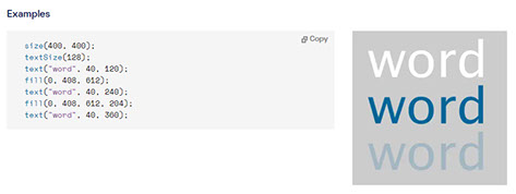
On this page we can support each other to program the typography within our figure
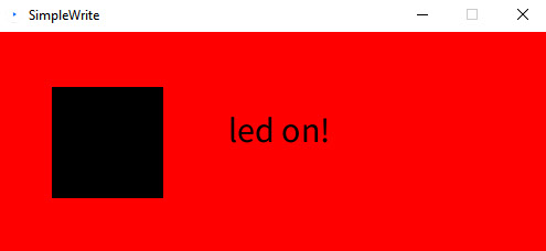

The box remains black and the LED off until we pass our cursor over it, it will change to green and the LED will light up
In the video you can see the arduino code to check the LED and the communication between the PC and our Board, then there is the processing software interface where we see the code that was loaded to the board to do the exercise