
Electronics design and production.
Characterize the design rules for your PCB production process.
For this assignment, we engraved a 100mm x 100mm PCB blank board using the tolerance test board.
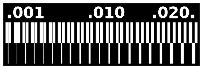
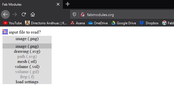
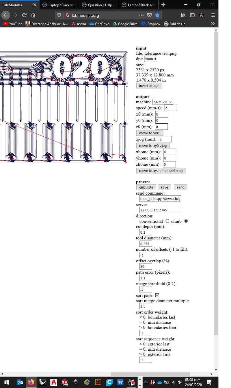
First, we imported the image to the FabModules inteface to set the minimum requiremnts in order to print and engrave.
Second, once the image is imported, we select the type of machine we would like to use.
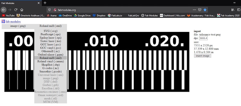
We look for the standard milling traces at PCB 0.010

Third, after setting the base points, we create a proof of print, with a single layer engraving path.
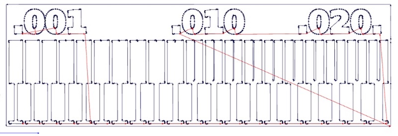
This settings will engrave just once, making something like this.

So, we need to set the proof of print to 5 passes to ensure the proper engraving.

To have something like this.

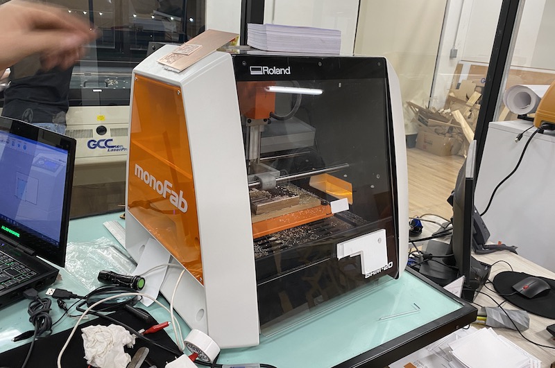
Fourth, we send the finished file from Fabmodules to the drilling machine
Roland Mill SRM-20 Technical specifications:
Work Area: 8" x 6" x 2.38"
Loadable Workpiece Size: 8" x 6" x 2.8"
Table Size: 9.14" x 6.17"
Max Tool Size: 1/4" or 6mm.
Spindle Speed: 3000-7000 rpm.
Operating Speed: 1.18 in/sec or 30mm/sec.
Mechanical Resolution: 0.00008in or 0.002mm.
Acoustic Noise Level: 45-65dB (A)
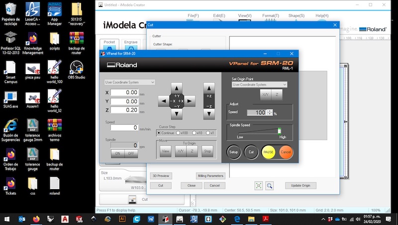
Now in the V-Panel program interface, for Windows®, we set de zeros and the logging to be able to engrave.
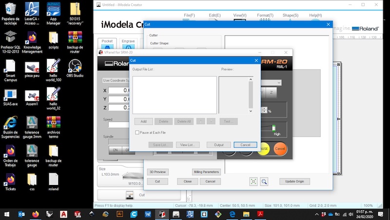
We open the window search to locate the file in the computer
We select the 1_offset settings
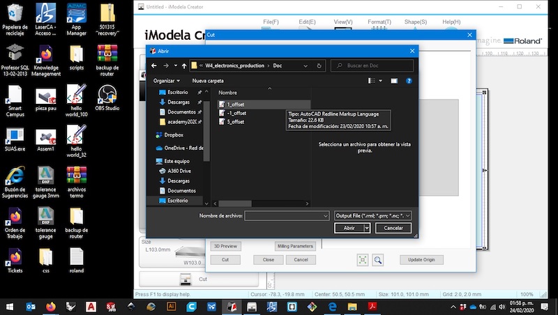
And chose the proper origin points and settings to finally send to engrave. We set the speed at 120, with a spindle of 8834 rpm.

As a final revision, we check that everything in Fabmodules is according to plan, from zeros to logging distance, as well as speed and size.
Then we have the finished engraving.
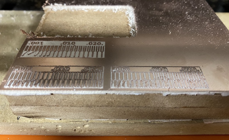
The main test proved to be quite harsh and we need a better drill, in order to ensure a better quality object.
However, the test at .010 proved to be a fair enough drilling task to have a basic circuit board.
We might try different test in the future with another drill.
For the next test, we observed the operation of a microcontroller circuit board.
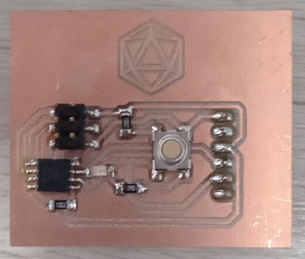
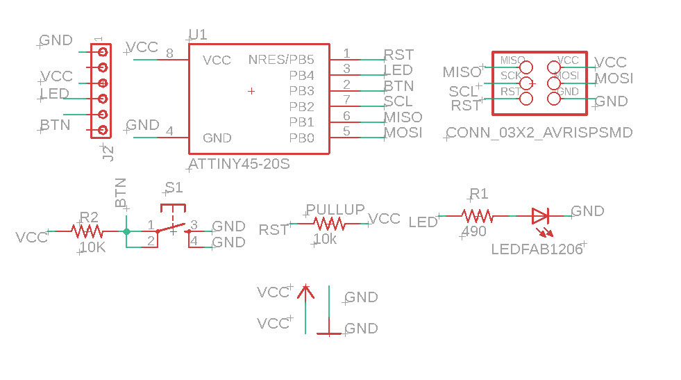
And this is the schematic of the board we just wanted to measure the dropage of voltage on the LED.
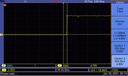
Here’s a screenshot from the oscilloscope we use on the right side of the screen we surveyed that it takes 1ms aprox to the LED to switch state.
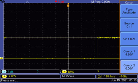
And here ,we can see that the voltaje on the LED is 4.8V this is because the voltaje used for the micro to opérate causes a litle drop from 5v to 4.8v.
