
A10
Mechanical design, Machine design
This week is collaborative effort with all our fellow students of the Node.
In this case, we as Ciudad de México FabLab, as a team, we decided to try designing a time lapse rail for a Smart phone, whether is an iPhone or Android, and integrate a myriad of printed, cutted and existent pieces.
The main background is based on a typical frame with an automated system.
Research:
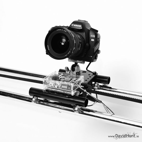
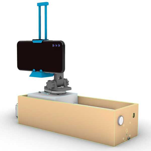
The original piece, is a time-lapse rail with a center timing belt that moves along an axis, and, the camera is attached to an articulated monopod mounted on a dolly.
Main specifications are:
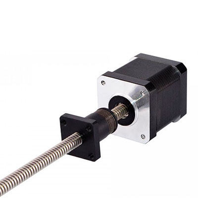
Nema 17 External 48mm Stack 0.4A Lead 2mm/0.07874" Length 300mm
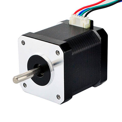
Nema 17 Bipolar 1.8deg 45Ncm (64oz.in) 1.68A 2.8V 42x42x48mm 4 Wires
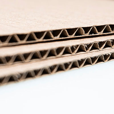
Single wall corrugated cardboard sheet available in brown, recycled and virgin papers, from SG to 55 ECT.
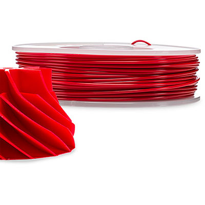
ABS 3d.printer filament (Acrylonitrile-co-butadiene-co-styrene Polyethylene terephthalate Polycarbonate)
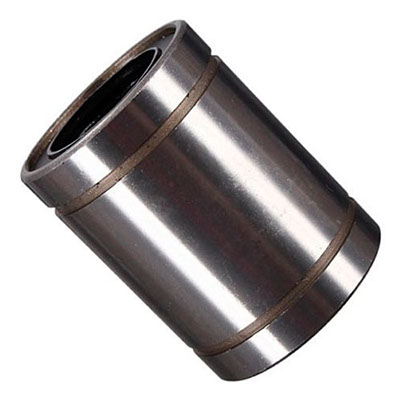
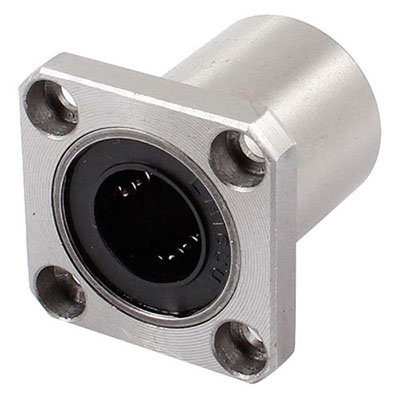
Horizontal bearing 1/4"
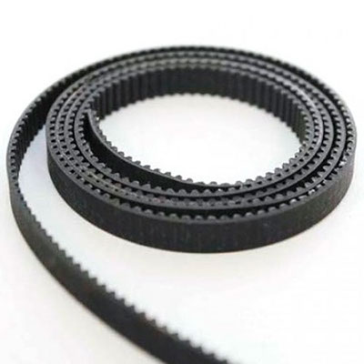
Timing belt 1/2" for printed dolly
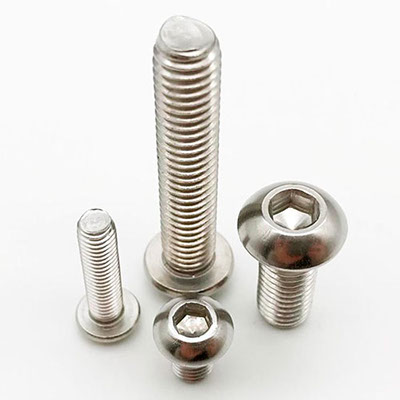
Socket head allen screw various diameters
Stainless steel Rod, 3/8" 2ft long
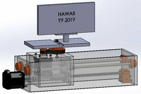
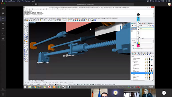
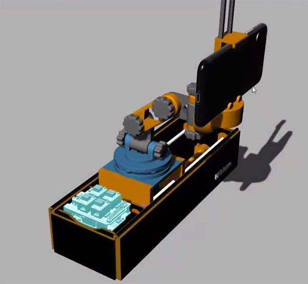
Main model was developed in SOLIDWORKS®, as a simple frame
Then, we translated it from STEP to Rhino and IGES files, for compatibility
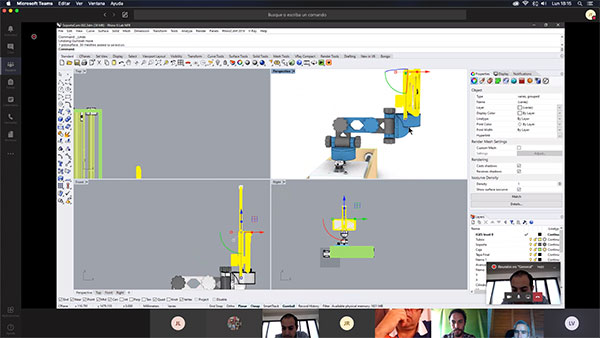
Here, is the process of fine tunning the whole model
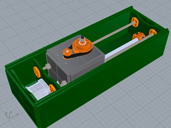
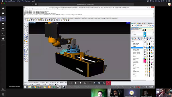
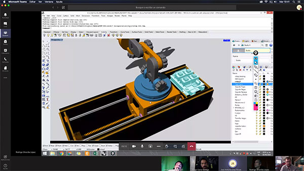
Here, is we are organizing the differnt pieces altogether tohave a perfect fit inside the box.
And here, we are collaboraing as a team.
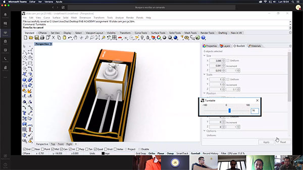
With this 3d model, we are measuring and defining the machine
We are using Solidworks and Rhino to achieve a better level of precision
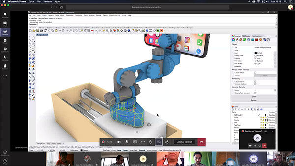
Not my field, however, we are considering a better anchoring to have better stability
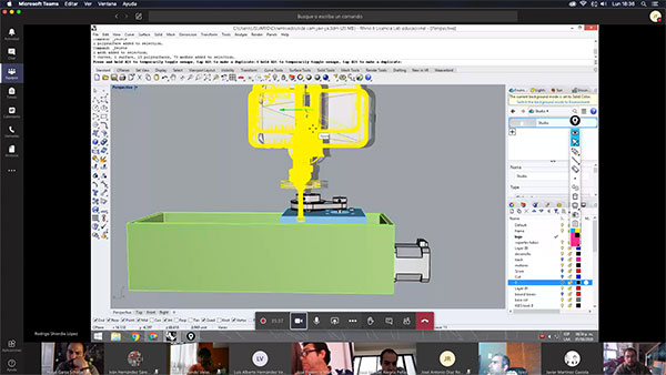
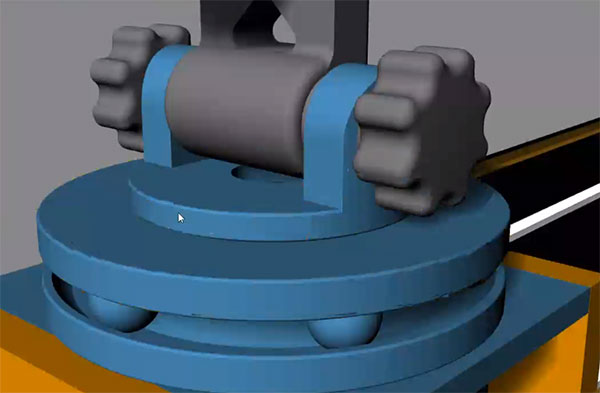
Here is a detail of the mounting piece
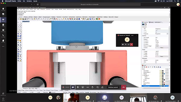
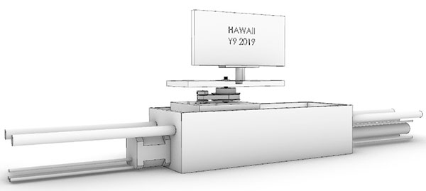
How to interconnect the rod bars and the moving lorrie
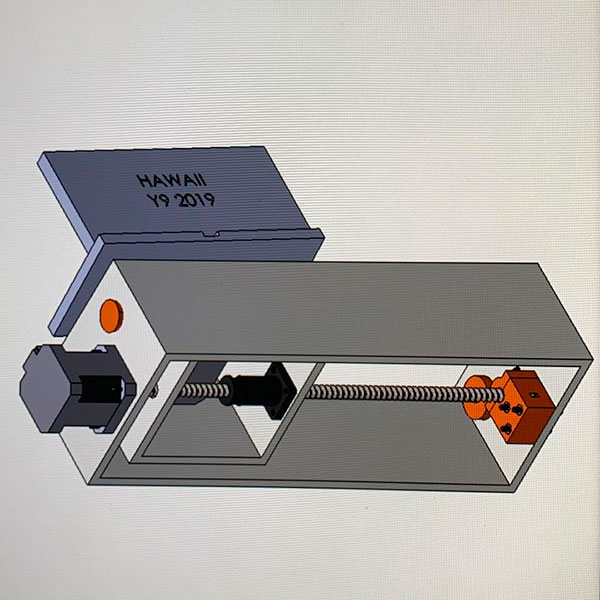
Exploded view of the rail
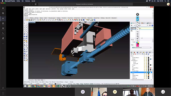
And how it is assembled in the 3d model.
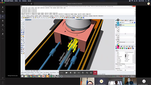
The detail of the final bearing system and mounting piece
The finished model waiting to be manufactured...
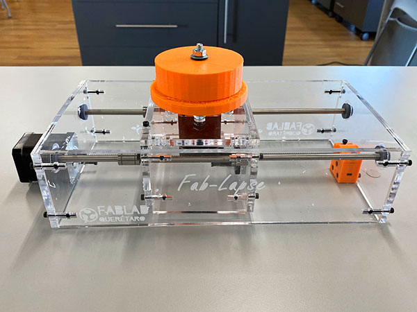
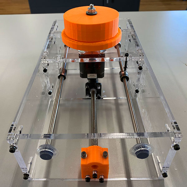
Now, after updating the main information, we decided to laser-cut the main body in acrylic to have a neat image, and a little bit of stiffness with the whole piece.
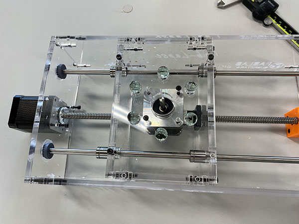
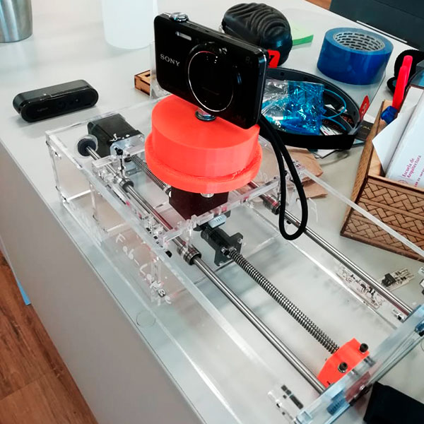
We finally, printed the camera base and put some bearing in the form of crystal-clear marbles
And let the lateral faces have some anchoring for the main board to be functional.
Art this moment, we are setting the programming and the code into de board to have along with ESP8266 wi-fi connector and through BLYNK software the main operation.
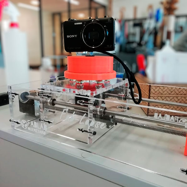
Partial conclusion:
This piece was developed in Querétaro, to have a second time lapse rail fully functional, we have partial access to the lab, will finish the task with a little different specifications and finishing the settings for programming.
