Jose Alegria - Fab Academy
![]()
![]()
![]()
![]()
Computer
Controlled Machining
ASsignment
wHAT iS THE ASSIGNMENT ABOUT?
Make (design+mill+assemble) something big.
Group Assignment:
Complete
your labs safety training
Test
runout, alignment, speeds, feeds, and toolpaths for your machine
Document
your work to the group work page and reflect on your individual page what you
learned
1st Step. Finding
an opportunity/necessity
The first
step is to find something big to build. The importance of the size in this
assignment is to make something that cannot be done with the laser cutter. So,
I was in the search for something that was big enough to be done with the CNC
and that could be assembled without any external help (i.e., without nails or
glue).
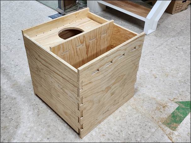
In
our Fablab, we needed something to keep the students
blueprints safe while rolled up, so I decided to make a container (600 mm x 600
mm) with space for papers and the rolled blueprints.
2nd Step –
Designing parametrically
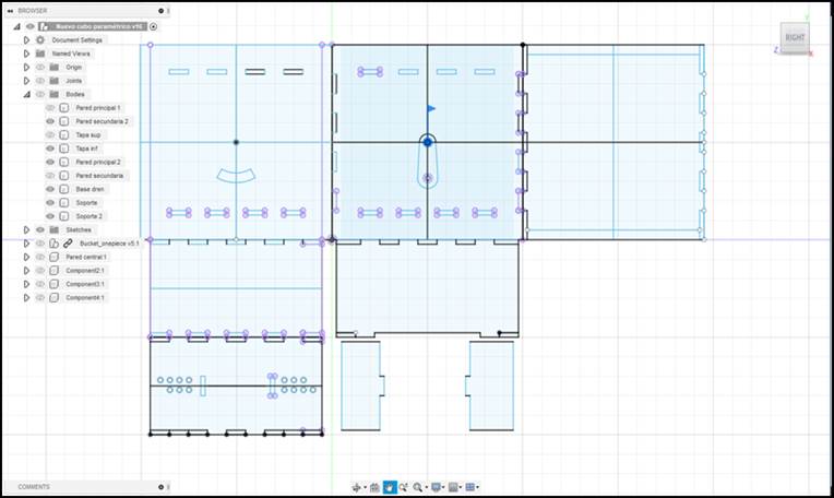
As I was going to design a container,
my needs were similar to the ones I had while designing a container for my
Final Project. While that was a case with special needs such as having dry
areas for the PCBs and wet areas designed to allow water through it, the
container I need for this assignment is a lot simpler. I decided to use my
original design as an origin for the new design, using the parametric settings
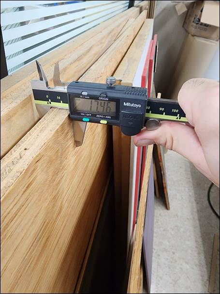
made in Fusion 360, I had to change the size of the panels from 100 mm to 600
mm and the size of the joints according to the material thickness, for I was
using a 3 mm acrylic for the final project case, and now I am using a 17 mm
pine wood sheet for my assignment.
After that, I had to consider the
differences in the cutting characteristics, for example, in the laser cutter I
had to be aware of the kerf changing the width of the joints, thus rendering my
press fit design harder to achieve. Here, in this assignment, the kerf could be
taken of the equation by designing in such way that the CNC cuts the wood
through the outside of the area to be used.
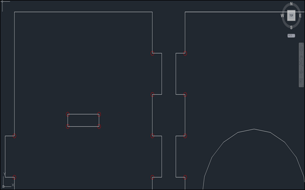
After changing the parameters
according to the new needs, I exported the design to Autocad
and made the final changes. For instance, getting all the pieces to fit in a
1.22 by 2.44 m wood panel.
3rd Step –
adjusting the design for the cnc cutting software.
After changing the parameters
according to the new needs, I exported the design to Autocad
and made the final changes. For instance, getting all the pieces to fit in a
1.22 by 2.44 m wood panel.
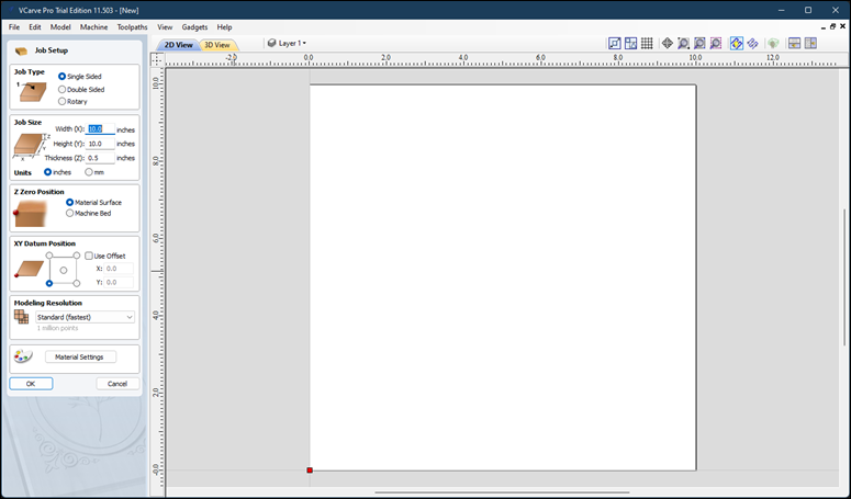
After that, I had to adjust the
parameters in the CNC Controller Software. I was using VCarve
to create a file that the machine could read. The first thing is to import our
DWG file to the Software.
There were three different jobs that
I had to create to cut the container: The first one was a set of borings made
to create a dogbone effect and allow the parts to fit
properly. I designed them to be just a hole with a diameter set by the tool I
was going to use (0.25 in).
The second and third jobs were the
main cutting procedure and was divided into two parts: the first passes and the
final cutting to split the parts from the main board. These are explained
ahead.
Inside the software I had to set the
parameters which were:
Job type
-
Single Sided
-
Job Size: 1220 x 2440 x 18.5 (mm)
-
Z Zero Position: Over the material
surface
-
XY Datum Position: 0, 0.
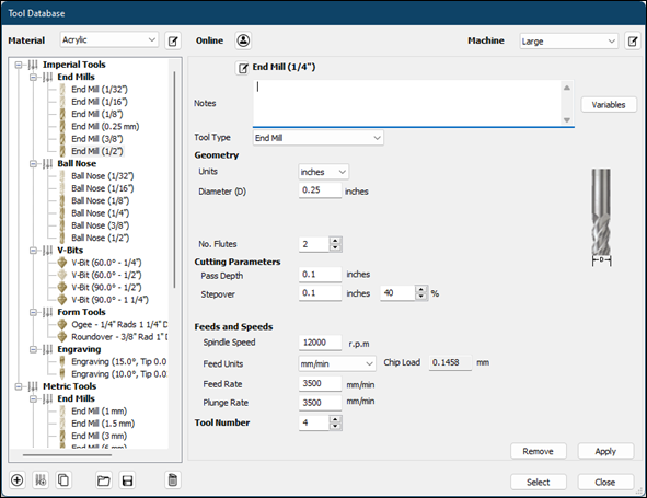
The
next step is to set up the cutting tool I was going to be using:
Tool
name: End Mill
Size:
0.25 in. or 6.35 mm
Spindle
Speed: 12 000 RPM
Feed
Rate: 6 500 mm/min
Plunge
Rate: 3 500 mm/min
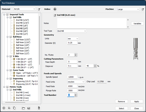
Cutting
parameters: our cutting will be done with a step depth of 5 mm (It was
programmed for three main passes with a depth of 5 mm, and a final pass of 3.5
mm).
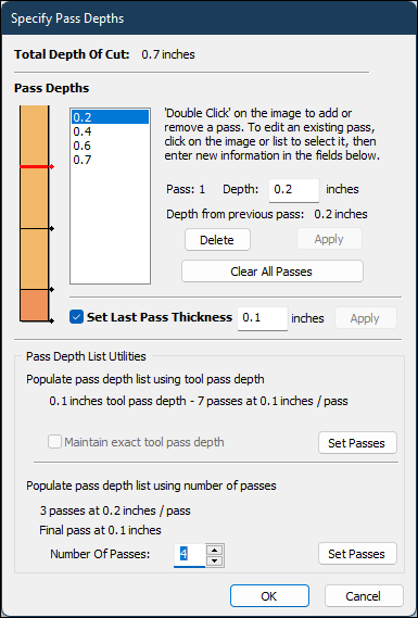
This
setting allowed me to set a faster Spindle Speed (6 500 mm/min) for the first
passes, the last pass of 3.5 mm had to be programmed for a slower Spindle Speed
of 3 500 mm/min to avoid the material to be moved once it gets separated from
the main board.
Once
the parameters are set, I let the software to provide the optimum cutting path
and it shows it with a diagram
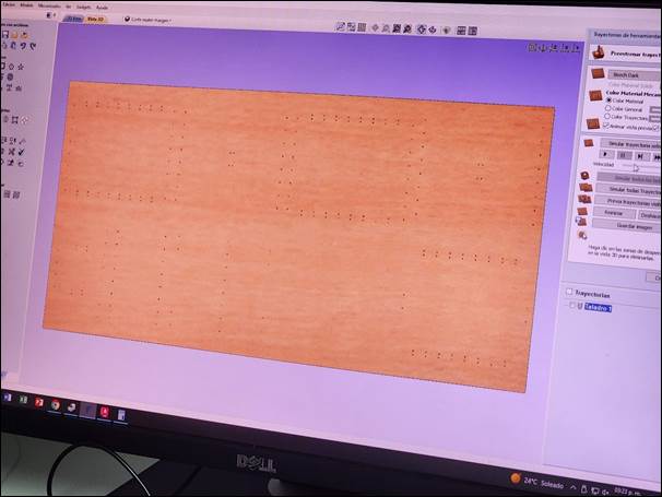
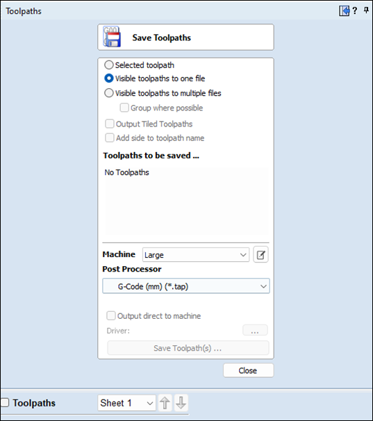
Now, we only need to export the
settings as a gcode file that can be send directly to the CNC.
5th Step – Setting
up the Machine
To
set up the CNC I needed to insert the cutting tool (0.25 inch cutter) and set a
few parameters before starting the process:
-
Set the lowest point to cut into
(Function 24).
-
Set the material thickness (Function
20).
-
Set the origin coordinates (Function
10).
These
parameters are set through the CNC Remote Control:
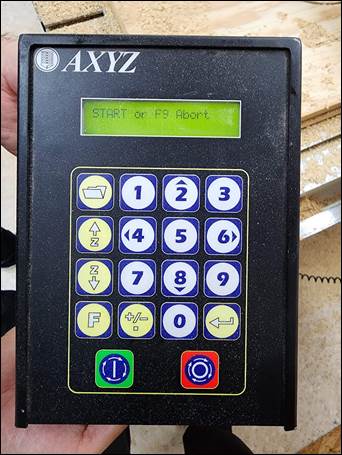
6th Step – Cutting
The next step
is to start cutting, I sent the instruction to allow the machine to drill all
the dogbones before cutting, this was working fine
until there was a problem with the cutter and it was broken during the process.
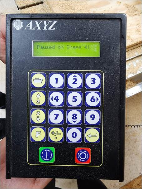
I changed the instructions to cut first and then drill, this allowed me to get
to know a different function: the machine can restart the job wherever you tell
it to. The machine displays where it is currently working when you pause the
job.
After that
incident, the process went straight forward:
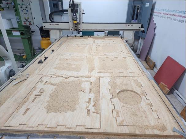
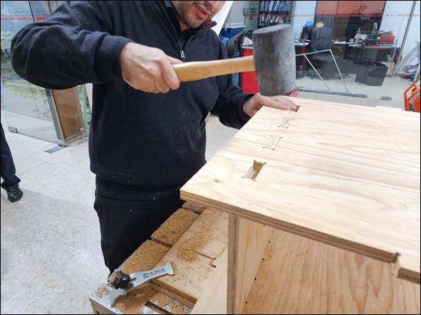
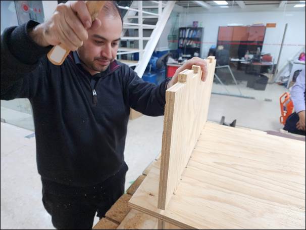
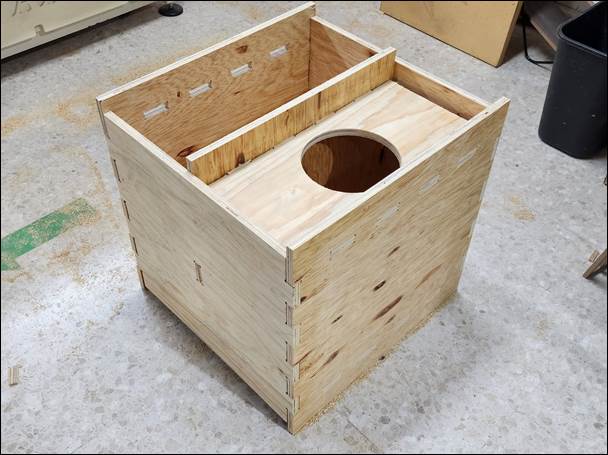
7th Step –
Assembly
In order to
assemble the container, I took off the parts that had been cut and started
cleaning them from burr by using a file, just to leave the assembly joints
clean enough to be assembled. Then, I assembled it using a mallet and nothing
else.
1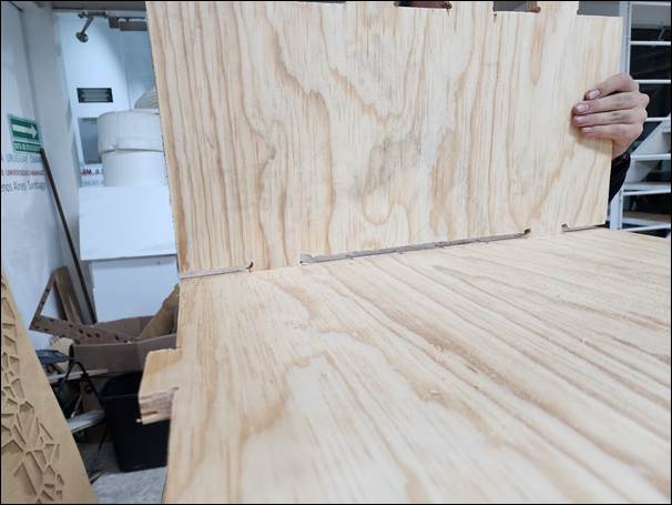

Conclussions
This was the last assignment I
completed. It was difficult to start the design but once I got the idea of what
to do I was able to solve the main problems that happened without suffering as
much as I predicted.
Original
Files
If you wish
to see or download the original files, click on the following links:
Nueval
Checklist
ü
Linked to the group assignment page
ü
Documented how you designed your
object (something big)
ü
Documented how you made your
CAM-toolpath
ü
Documented how you made something BIG
ü
Described problems and how you fixed
them
ü
Included your design files and hero
shot photos of your final object.
2022