Jose Alegria - Fab Academy
![]()
![]()
![]()
![]()
3D
Printing and Scanning
Assignment
wHAT iS THE ASSIGNMENT ABOUT?
This is the first approach to 3D printing and
scanning. The goal is to create something by ourselves.
1st Step. Group
Assignment
The group
assignment was to characterize the 3D printing machinery available in our
fablab. We got one 3D printing test file and printed it with all the 3D
printers in each of the different labs.
·
Assignment
3. Group Assignment. 3D Scanning and Printing.
We
worked with one of the printers for each one of the students in Mexico City.
2nd step. Using
the printer
Once the
local equipment was characterized, we could start making the first tests to be
able to understand the logic behind the 3D printers. This was a very important
step, because while we were doing the group assignment only one person at a
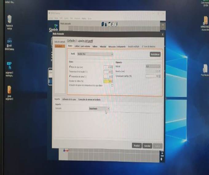
time can control the equipment. So, the first thing I learned was that the
equipment we have in our Fablab there are two standard setup menus: basic setup
and advanced setup. The basic setup has a few default settings whose main goal
is to ensure the correct execution of typical work, while the advanced setup
gives us the chance to modify certain parameters to achieve one or more of the
following goals: a reduction in material usage, a reduction in time of
execution, and/or to develop figures or geometries which the basic settings
will not do, mainly through the construction of custom supports or bases.
3rd step.
Designing process
We were told
that the assignment was to be able to print a design that was not achievable
through a subtraction process (i.e., cutting), so I started visiting webpages
to learn what has been done with 3D printers, and to understand the reason to
use this process and not laser cutting. During this research, I found that one
of the functions that I could not find in our laser-cutting assignment was to
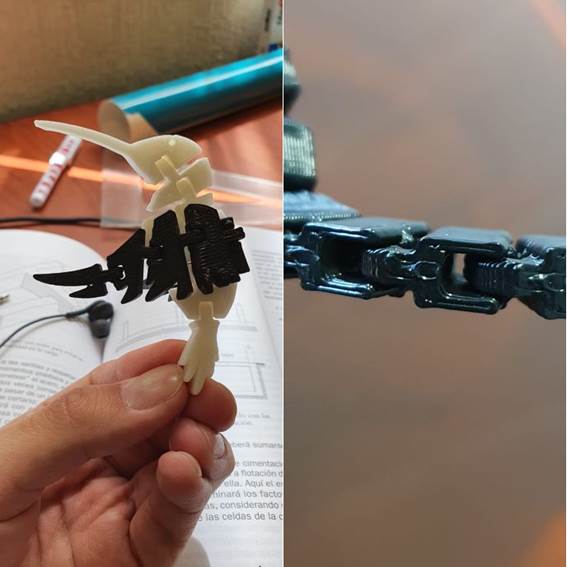
achieve joints that were able to move, and that there are hundreds of examples
where people can get their models to move through this joint. To understand the
process behind these pieces I printed one model that I downloaded from the web.
With this, I accomplished two objectives, to use the printer and get to know
the consequences of moving the parameters and settings, and to check how did
other people had built these joints.
4th step. Making
my own design
Once I knew
what I needed to do, the next step was to start making the design of my own
prototype. The goal is to continue testing different materials to build the
bridge I designed the last assignment:
·
Assignment
3. Laser-cutting.
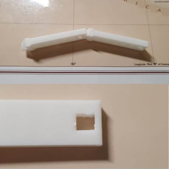
I had
to develop new joints for the bridge, this time they were made using
3D-Printing. Using the information obtained from the last example (the
hummingbird), the beams were designed thinking in letting them move freely in
one axis, just as the truss elements work in larger designs.
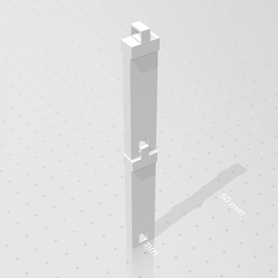
Once
the design requirements were defined, I started designing them in Fusion 360.
The beams were designed to be interlocked to deter movement in two axis and to
provide free movement in the other one. As with every design made for this
course, the design has parametric constraints to allow size changes to be done
without any difficulties.
5th step. 3d
Printing
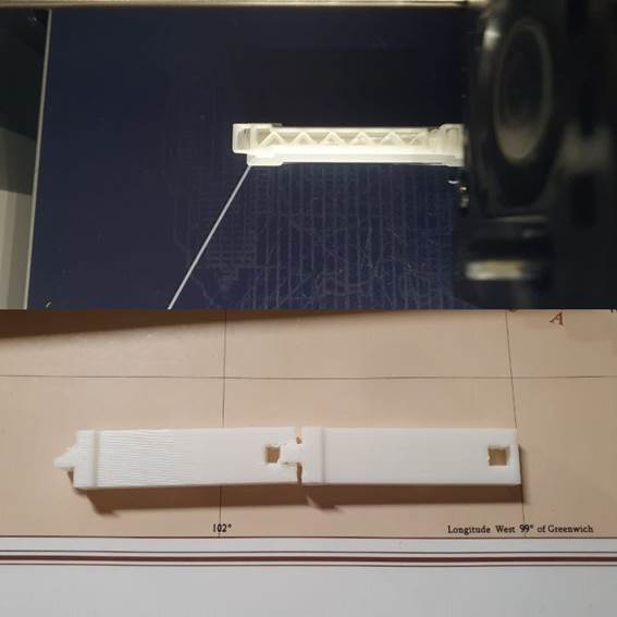
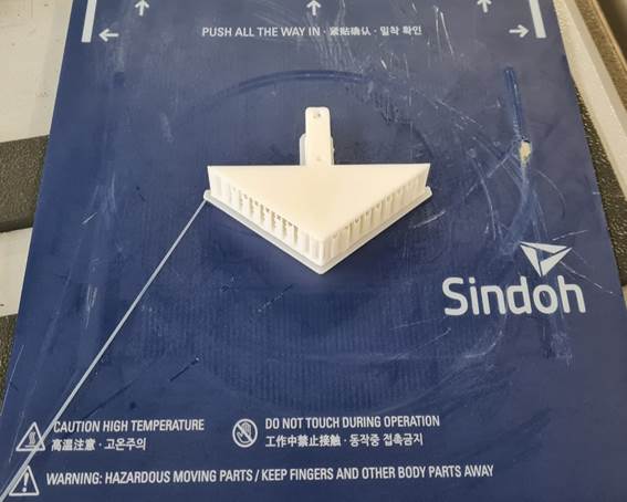
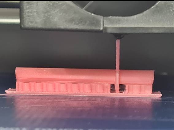
Finally, I had the joint design
ready. Then, I converted the file into a format that the printer would
recognize [stl] and proceeded to print. There were a
few problems at the beginning because the model wouldn't stay up, After
evaluating using different kinds of internal supports, The main axis was rotated
so that the plastic had time to cool down and gain resistance, so finally it
worked and the model was printed.
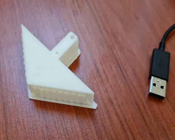
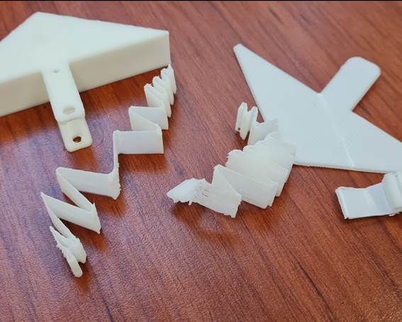
6th step. Further
changes
Once
it was printed, I noticed that my design can be upgraded, for example, I could
fillet the edges so each piece could rotate freely without bumping into the
next piece, and that I could change the joint into a circle so the design would
not require any more support that I had to take away after the printing.
I
will make these upgrades during the following days so I could get all the
pieces together and build the truss bridge.
7th step. Final
project 3D Printing
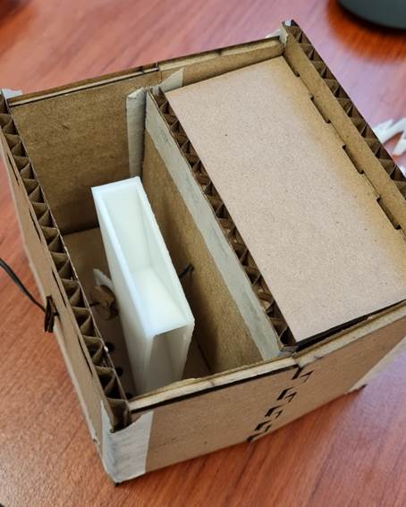
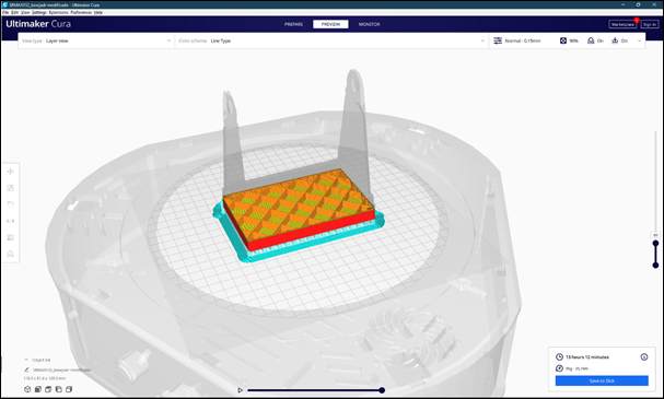
For
my final project, I have two components which are going to be 3D printed: a
bucket and a device to translate the movement from the bucket to the sensor,
these two components have different needs, mainly because one of them is larger
and made with a square design, the other one is not only smaller, but it needs
to be completely round and of an exact diameter.
The
first part was easily printed in the 3DWOX printer, which is the most used
printer in the lab, and having good overall results.
The
second component was printed in the same printer, but as the diameter is not as
precise as expected, it became very difficult to assemble once in the main
project.
The
fastest solution was to use an Objet 3D Printer, this
is a different technology printer as it uses a PolyJet
technology to print with a fluid material instead of using a filament thus
rendering possible to create an almost perfect circle in the small diameters I
am using (1 mm – 1/24 in.).
8th step. Scanning
Scanning
is a process where we can convert any object into a 3D file to be able to work
with it or simply to print it. This process may be achieved with different
kinds of scanners that are available in the market. Each scanner is optimized
for an specific purpose, so, when choosing the scanner to be used, you should
take this into account (in this case is even more important than in any other
equipment available in the Fablab).
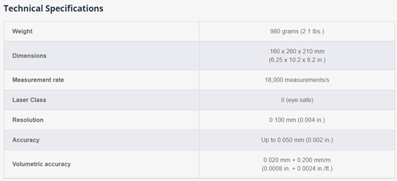
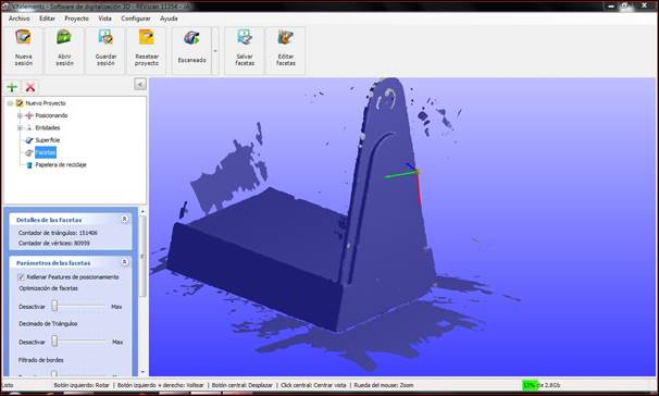
My
first approach was with the Creaform Revscan Scanner. This is a reverse engineering and design
applications dedicated scanner. This means that we will have a very high
resolution file, but that limits the size of the object to be scanned.
It
starts with defining the size of the file you will be getting after the
scanning process, that will help to set the resolution that you are going to
need, this is very important because with this equipment you can get large
files that will become difficult to manage.
Once
you define the resolution, there are two ways to make the actual scanning:
1.
Grid of points: You should tape or
paste all over the object to be scanned a grid of reflective points that will
help the scanner to navigate around the object, allowing you to start in any
position and pause the scanning process without having any troubles to finish
the work later. Once you have made a pre-scan to let the scanner make a map of
the reflective points, you can start with the thorough scanning process, which
will be automatically adjusted into the reflective points map. This process is
easy and effective when scanning an object that lets you paste the reference
points.
2.
Direct scanning: If you cannot paste
the reflective points, then you can still make the scanning but without a
reference grid that allows you to restart the scanning process at any point.
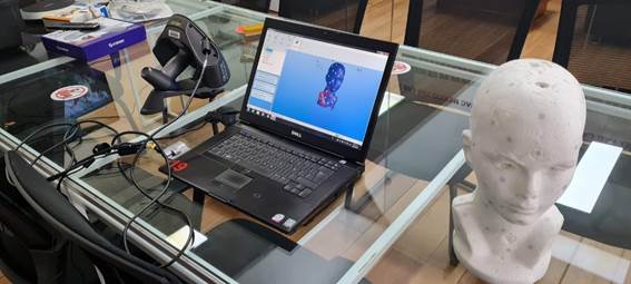
For
this assignment we decided to scan the lower base of my colleague Jose Antonio.
I followed the same steps:
1.
Use the position features to allow the
scanner to navigate around the object:
2.
Scan
the surfaces and create an object within the system.
3.
Correct the surfaces by erasing the
areas not intended to be part of the 3D object.
4.
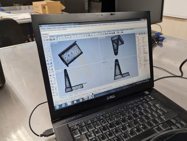
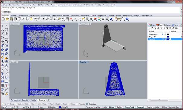
Export the file and modify it by
adding the second part of the object. I did this because it was a symmetric
object that could be easily get finished with Rhino. If not, we could just finish
the scanning process.
5.
Export the final object as a stl file.
Conclussions
It was important to learn that there
is no perfect technology to create something, the PolyJet
is more expensive but has a higher precision, on the other hand the Filament 3D
Printer can help me to easily create different versions of the object I am
trying to design, allowing me having different versions and analyze the
advantages of each one.
Original
Files
If you wish to see or download the original
files, please follow the links:
1.
Fusion
360
2.
STL
File
Nueval
Checklist
1.
Linked to the group assignment page.
2.
Explained what you learned from
testing the 3D printers.
3.
Documented how you designed and made
your object and explained why it could not be easily made subtractively.
4.
Documented how you scanned and
prepared an object (for 3D printing).
5.
Included your original design files for
3D printing (both CAD and common format for 3D printing.
6.
Included your hero shots.
2022