Jose Alegria - Fab Academy
![]()
![]()
![]()
![]()
Computer
Controlled Cutting
ASsignment
wHAT iS THE ASSIGNMENT ABOUT?
The goal for
this assignment is to develop a way to parametrically design a project to cut
it with the laser-cutter, and finally to report the learning process.
Group
Assignment:
Characterize
your lasercutter’s focus, power, speed, rate, kerf,
and joint clearance.
While
doing the group assignment I learned:
·
The machines have different functions
we will not be using during our fabacademy projects, nevertheless
we should at least know what they do and where we can find the information in
the case we need to learn more about them later. For
example, the engraving features of our laser cutter.
·
The same will happen with some of the
parameters that the machines allow us to change, even if we don’t inquire about
them for now.
·
While making the cardboard
parameters, I found that different materials need to be treated differently
because of special conditions, for example: if I tried to engrave over the
cardboard a different letter font, what I would get was a few holes over the
first layer of the cardboard.
1st Step. Vinyl
Cutting
For this week's
assignment’s first part, I have decided to use the vinyl cutting machine.
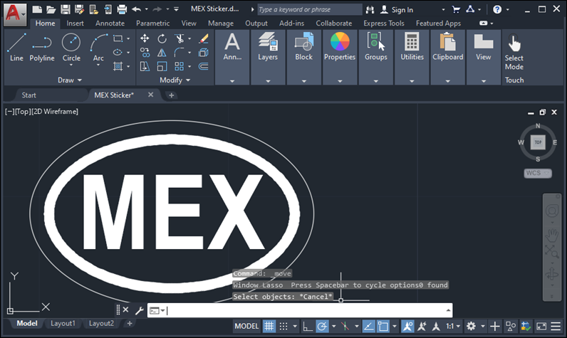
I made a very
simple drawing in Autocad, an international oval ID
sign displaying MEX to make a sticker, I saved the drawing as a DXF file in
order to be able to export it, and use it in the machine, as I was suggested,
prior to get into the machine's software, I made a copy of my drawing in a
different file format, so I've got a .eps file, as well as a .plt one using Corel to make this changes.
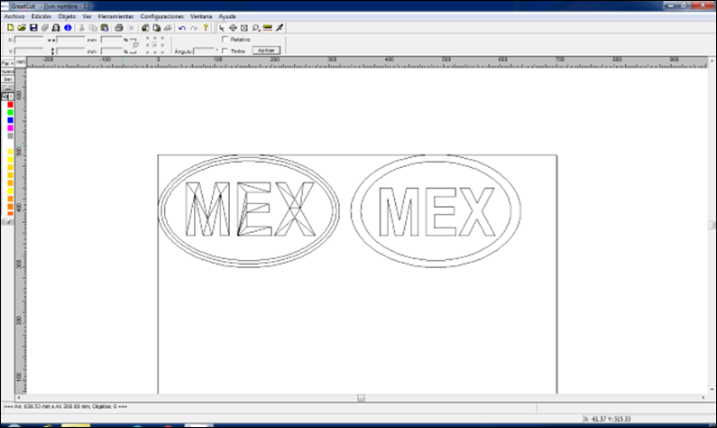
Then
I have got into the vinyl cutting machine software. It's called GreatCut, and it's essentially a blank canvas where you can
import the different files.
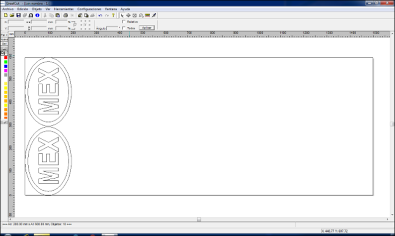
At
first, I tried with the DXF file, but it was rather not compatible as it showed
a distorted image of what I have
drawn,
then I used the eps which changed the drawing by splitting the vectors into
triangles, so at last I used the plt file which
displayed the image as it was intended to be.
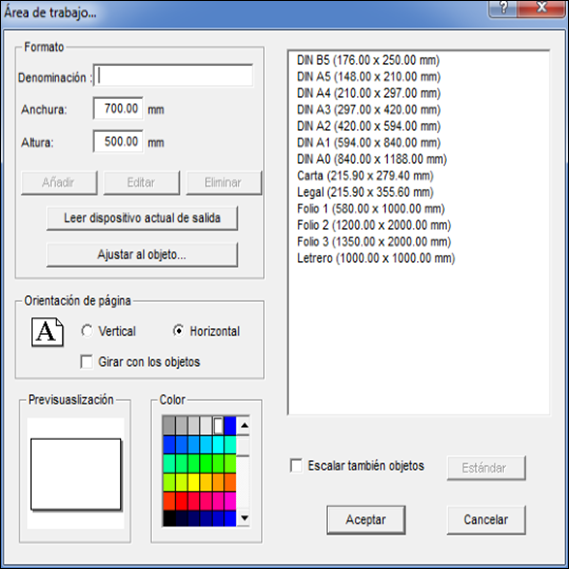
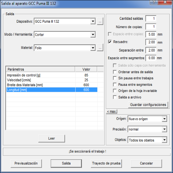
Then,
you must set up the machine with the vinyl or the material you're going to use,
setting the sheet dimensions, and finally you get to the tool's menu where you
should specify the parameters you need the machine to use, as the speed and
force, and for some reason, you must set again the material dimensions.
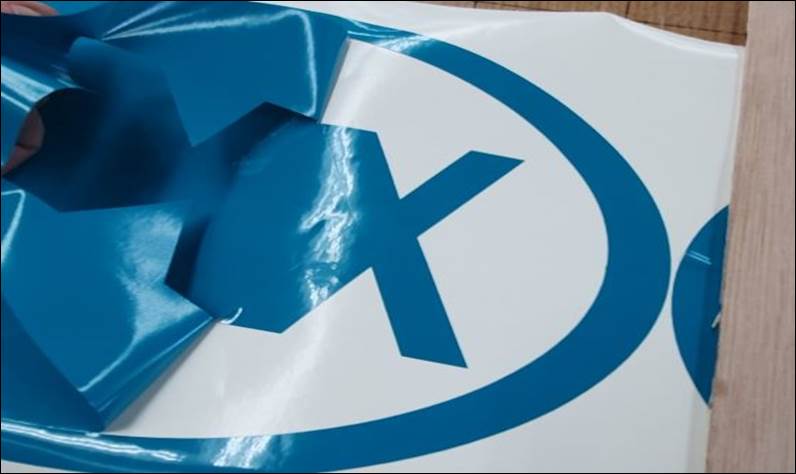
Once
you're over that, you must get the material into the machine and click OK.
2nd Step –
Designing For Laser cutter
The assignment was to make our own
construction kit with the laser cutter.
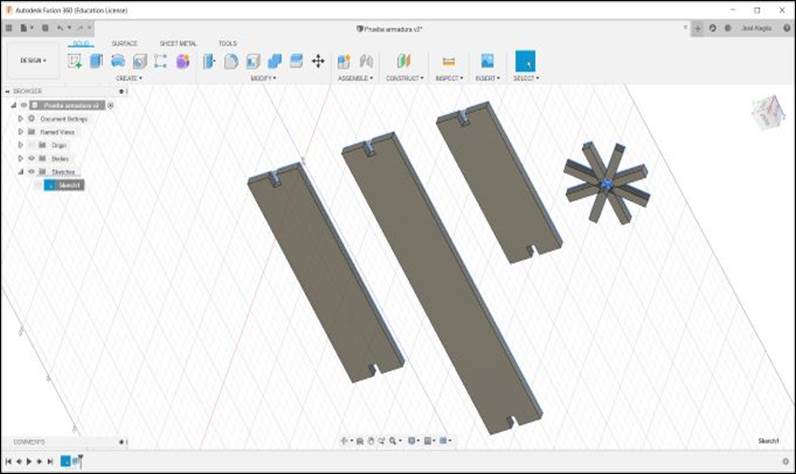
I designed a truss bridge that could
be made as long or tall as wished. The first part was to design the pieces, so
I used Fusion 360 to make a parametric design in which I could change the
dimensions of the bridge pieces as I wanted and they
should stay aligned in a way that made the construction possible.
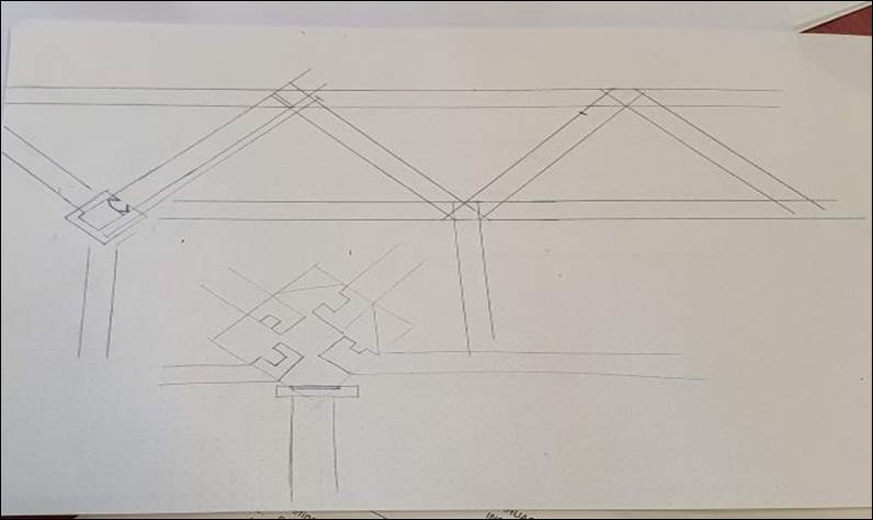
I made a draft to try to design the
main components of the bridge, the most difficult part was to design a joint
that would keep the different components in their place.
I came up with an idea in which all
elements should be compatible with the joint. Once I had the design made, I
made a DWG file with the pieces I was going to cut.
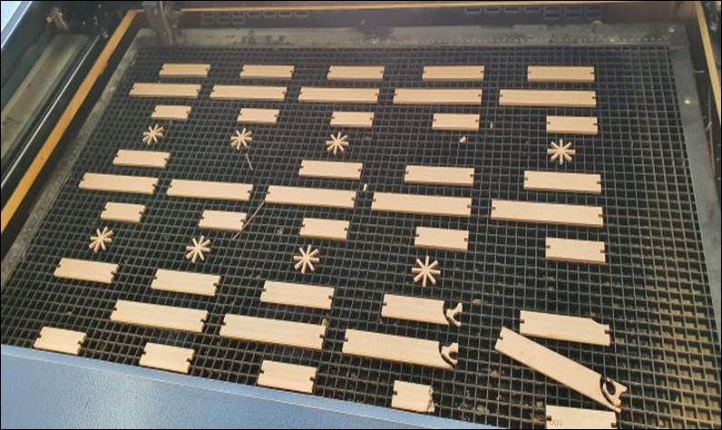
3rd Step – cutting
with the laser-cutter
As we did the
group assignment before the individual assignments, I already had the
laser-cutting parameters needed to cut all the pieces I needed.
So,
the task was half done, I only had to set the parameters and then I was able to
cut.
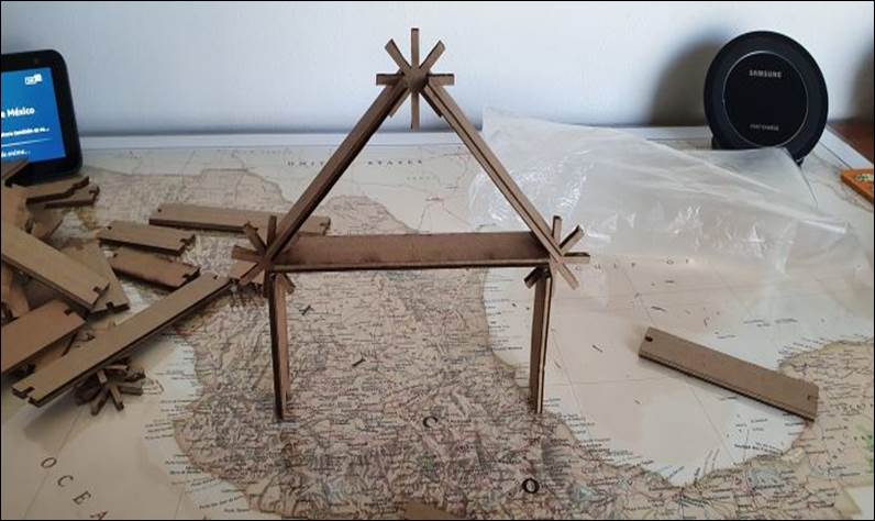
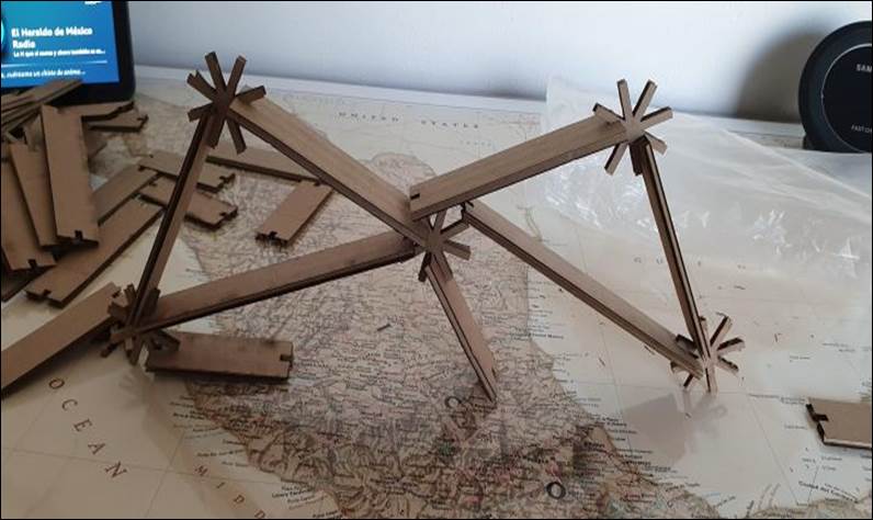
4th Step –
Assembly
Having
cut my construction kit, I started building the truss bridge. The cardboard
wasn't as rigid as I thought so the small joints I cut
weren't able to keep the structure up, I think the design could work if I
repeat the assignment with a stiffer material, maybe I could use MDF for the
next attempt. I'm posting here the structure as I was able to assemble it.

5th Step – New
Design for the final project
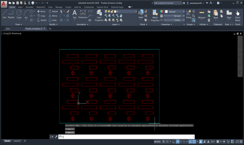
For
the final project I tried a new approach to the parametric design. Using Autocad for parametric design proved difficult and slow,
due to the constraints needed to be used, so I tried to design with Fusion 360.
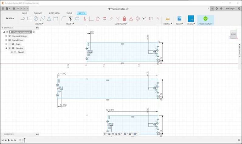
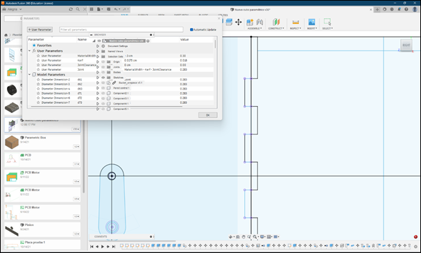
First,
as I explained in the last assignment, if designing in Fusion you should start
by making 2D sketches of the bodies that you will be using. This
sketches should be thought to be converted into bodies by extrusion, so
when you cut certain material in the laser-cutter it will become the parts you
want to assemble.
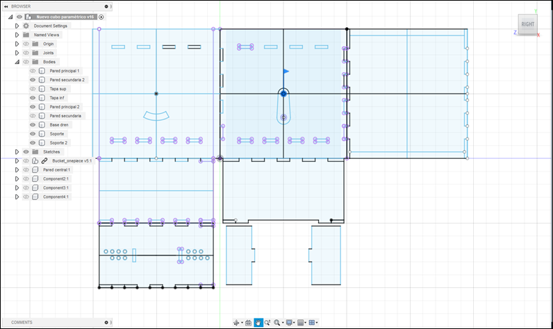
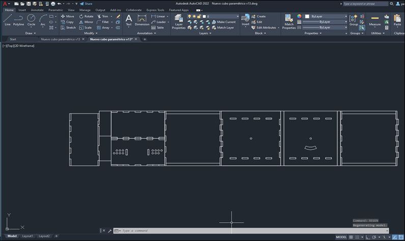
These
are the parametric sketches I made in Fusion 360, they have parametric measures
that helped me to cut in different materials, mostly changing the size of the
tabs accordingly with the material thickness, also to change the size of the
container to make different tests and redesign the container as I discovered
new needs to be considered.
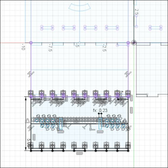
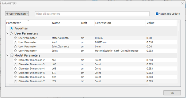
To
accomplish this you should take kerf into account. The
Kerf value is the width added to the cut by the laser during the cutting
process. This value is characteristic of the material being used and the method
of cutting.
To
take that value into account you should add it to the parameters you are
designing with. For example: in this case I parametrized the size of the
notches in my container to be the result of the material width minus the kerf.
If the adjustment is not tight enough you can add another adjustment setting.
This
will help for easier parameters change if you should modify your project.
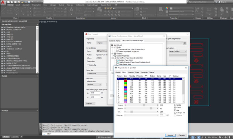
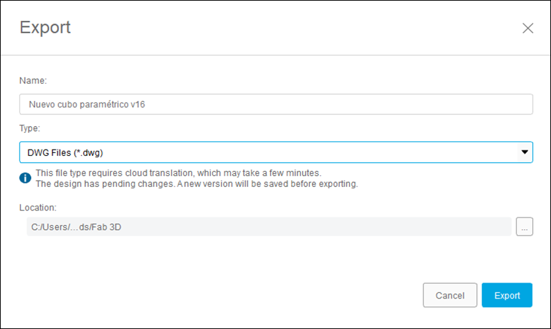
After
designing in Fusion, I exported the drawing to a dwg file to be used with the
laser-cutter machine. It is not as straightforward as I thought it would be,
but it is not as difficult to use as it was to design directly in Autocad.
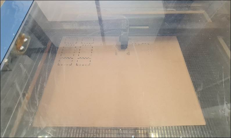
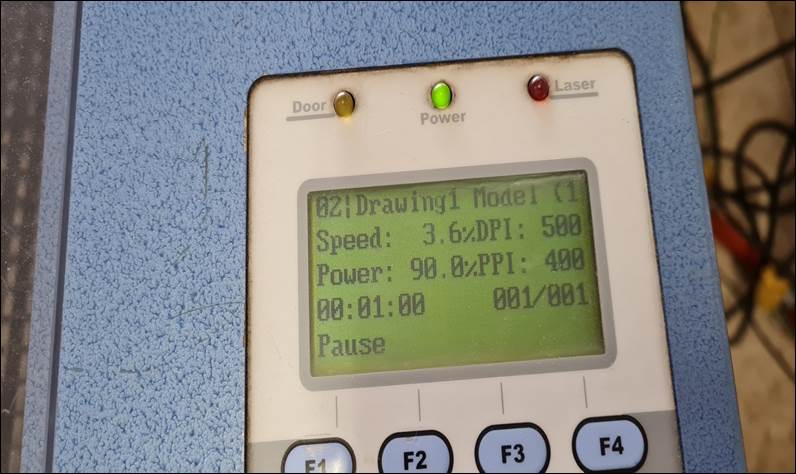
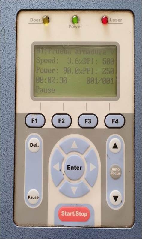
The cutting parameters for the first material
where as I stated them in the first part of the assignment, I cut the design in
cardboard to test it and find any detail that could be missing from my original
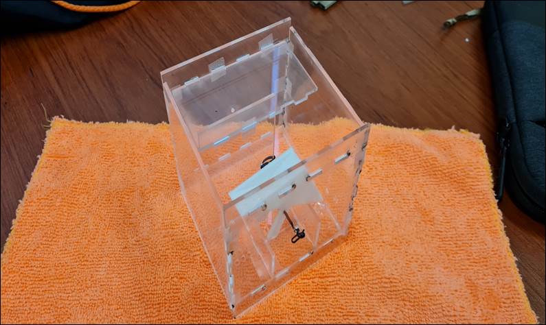
design. After a few revisions and a few new versions (exactly: 14) I finally
got to my final design and cut it in acrylic (instead of cutting at a 3.6 in/sec
90% power setting, I used a 0.7 in/sec 70% power setting).
|
Material |
Speed |
Power |
|
3mm cardboard |
3.6 |
90% |
|
3 mm acrylic |
0.7 |
70% |
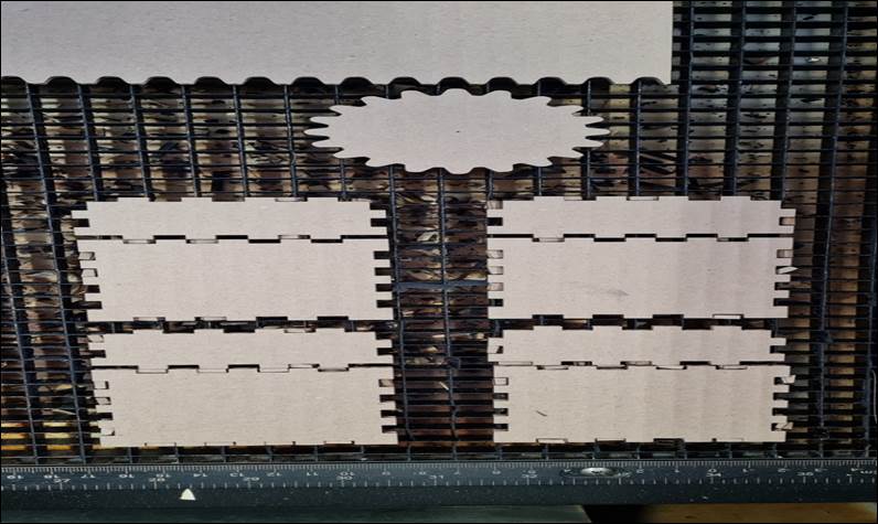
Here
is a photograph of the different versions cut and assembled.
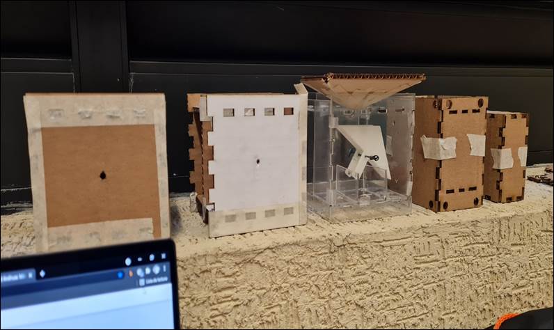
After
so many versions, I made extensive use of the timeline feature within Fusion
360. This feature helps to know when you started changing a certain part of
your project and what were you doing with it.
Conclussions
This assignment importance was to design
a webpage to keep track of our work, and to be able to demonstrate the steps we
would have to follow to replicate each assignment.
Original
Files
If you wish
to see or download the original files, click on the following links:
4.
Fusion
360. Cubo parametrico
Nueval
Checklist
ü
Linked to the group assignment page
ü
Explained how you parametrically
designed your files.
ü
Documented how you made your
press-fit kit.
ü
Documented how you made your vinyl
cutting.
ü
Included your original design files.
ü
Included your hero shots.
2022