Jose Alegria - Fab Academy
![]()
![]()
![]()
![]()
Computer-Aided
Design
Assignment
wHAT iS THE ASSIGNMENT ABOUT?
The goal for
this assignment is to create anything using a parametric design.
1st Step. Tool
selection
There are
many different CAD designing options. For this assignment I selected two
different and quite opposite designing options. The first one was Autodesk's
Fusion 360 which I could use by downloading the student version, and the second
option was using an open-source program: FreeCAD. I
had not worked with either of those before, so I will have to face the same
learning curve for both.
There is a
wiki quick guide with a few instructions and tutorials, it really helped me out
to start the new designing progress.
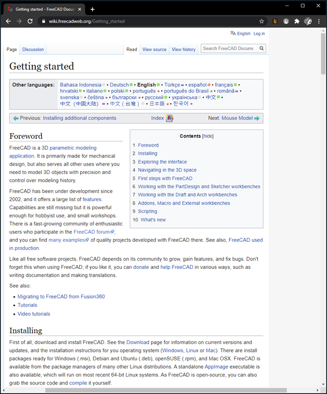
Despite
having the quick guide and a few references on how to start designing, the
learning curve for starters is steep. So, I tried out the second option.
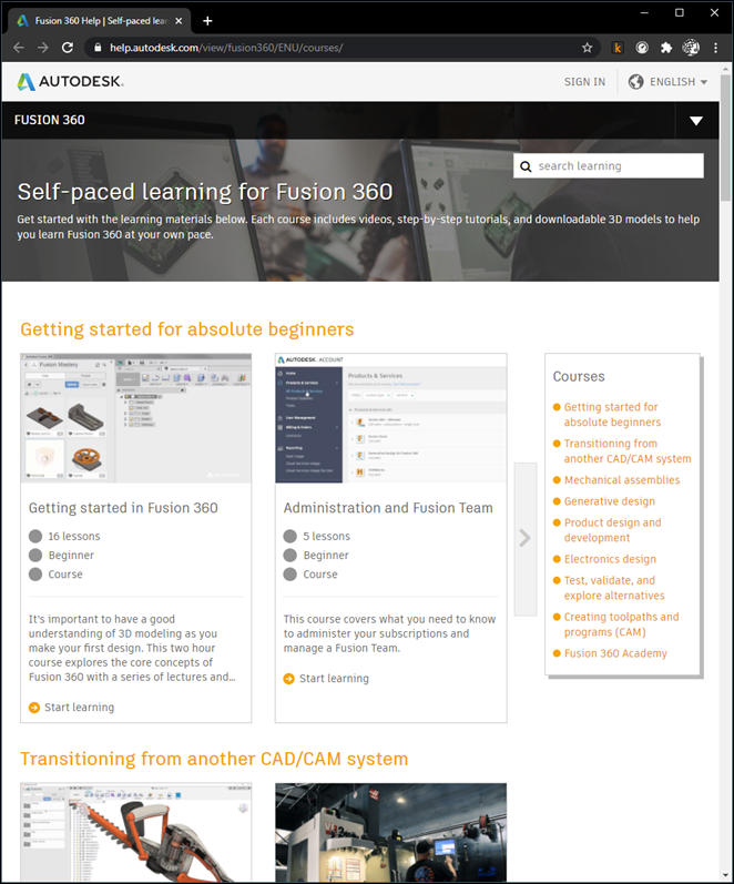
I started
working with Fusion 360, hoping it was going to be as easy to use as Autocad. The first thing I did was to try to draw something
in the canvas but as I was trying to connect the first two elements I draw they
kept merging into one object. So, understanding that it was not going to be
that simple, I watched some videos that Autodesk has in it's
website where they explained the importance of using components and bodies in
order to be able to turn the elements on and off, as required. This had another
important consequence, I was able to join the different bodies I was drawing
and still have two objects with different properties.
2nd Step.
parametric Design logic
The process of modeling in Fusion 360
gets easier as you understand the logic beside it.
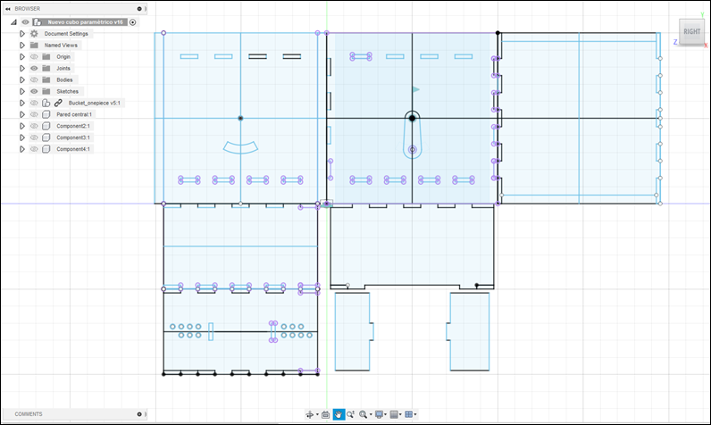
The first thing you must do is to
separate the object you are trying to model in its component parts, in my
project, where I was going to build a traffic signal, the first thing was to
model each of the lights as separate objects, to only replicate them as needed
(e. g. two build a single light beacon, or a protected left turn four lights
system). After that, I had to repeat the process of dismantling the object into
smaller component parts until I found myself only with simple objects that
could be modeled as one.
Then you must make a 2D sketch of
what you want to see in 3D, the program gives you the choice between the 3
axes, and changes to a flat drawing canvas when you set your choice. There, you
should draw a flattened 2D version of what you are going to transform in a 3D
object via extruding, or revolving.
Finally, you should be able to change
the physical properties of the object, such as material or color.
Once you have your objects drawn and
linked with each other, now you must replicate them, I used the command
Move/Copy to make exact replicas that will have the same properties between
each other so I could make a change in one of them and all its equal objects
would change with it.
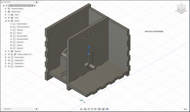
3rd Step. Starting
a new Design
I restarted
working with Fusion 360 when I changed my final project, there are some
considerations to be considered if you want to develop a project in this
software:
a.
Design layers:
To make a successful model you must design it
while thinking of small pieces that will merge when the design is over.
These layers must be:
a.
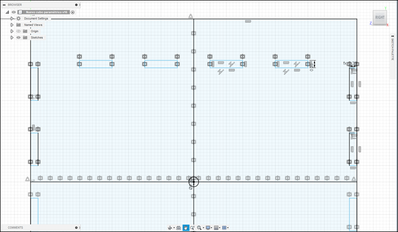
Sketches:
These
are the simplest way to design in Fusion 360. You will be designing over a flat
canvas which allows you to use basic drawing tools.
If
you want to make a parametric design this is the level in which you can make
the constraints needed to control the parameters of your design.
b.
Bodies:
These
are the second level designed objects in Fusion 360. A body is any continue 3D
shape. Sketches can become bodies by extruding or revolving around the flat
surfaces you drew while sketching. In this level you’re allowed to give the
objects a material and other properties. If you copy/paste a body, each one of
them will be independent.
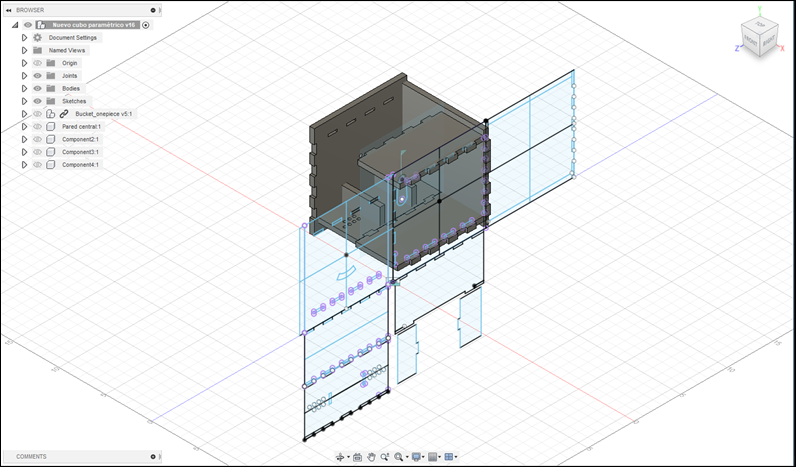
c.
Components:
Once
you design a body or group of bodies that will be made as one part, you must
transform them into components. Components are capable of motion and keep track
of the objects that became the component (i. e.
bodies and sketches).
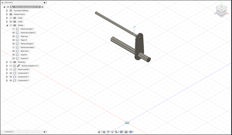
Components
may be exported and used in different projects or designs. They will be
affected if you make changes to the original component.
You
can join different components with joints and set up a particular movement
between them, allowing you to understand how the design will work when
manufactured.
d.
Ensemble:
An ensemble is a group of components working
together, this is what will make your design upper level. Different components
will be joined by joints which will limit the way in which two or more
components interact.
4th Step.
Rendering
Fusion
has a rendering tool that makes it possible to create a more realistic image of
the design you are working on. It has two different levels of production, a
quick render called in-canvas render that can produce a quick image where the
materials are simplified. This could be useful to make sure what you are doing
will have the results you are looking for. This is great for basic materials
and rapid jobs.
v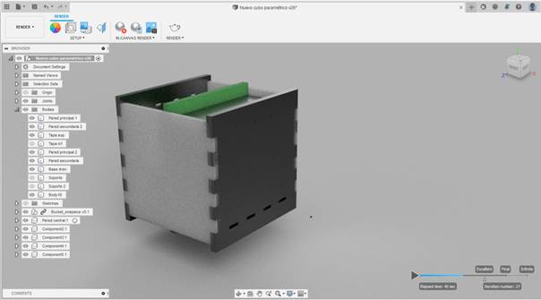
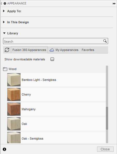
You
can select from a variety of materials that are in the Fusion 360 library,
which range from plastics, metals, glasses, and a few more options. They can be
located by using the function Appearance within the render menu.
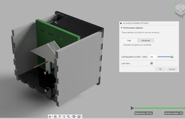
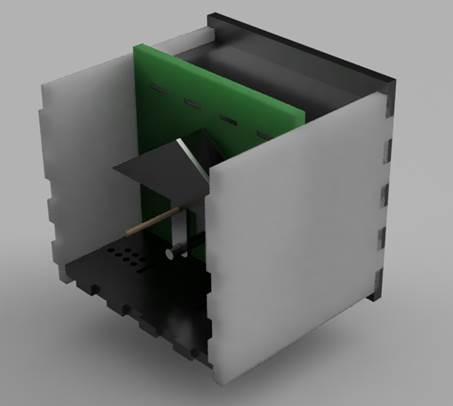
For a professional job, you can send
the document to be rendered by a cloud rendering service that will work
remotely and make a more complex render based on user-defined settings. I tried
it and got this as the simplest of the results:
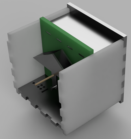
This
is another try with the options set to high quality, took 10 minutes to be created:
Extra Step. Raster v. vector
For
the last part of this assignment, I tried two different ways to create a
digital image: Raster and Vector.
Raster
recreates an actual object by arranging a series of pixels one after another
and giving to them the characteristics needed to become (at the distance) the
image of the object to be displayed. Having this into account gives us the
chance to change this properties and modify the image, this is the principle
behind the image editors.
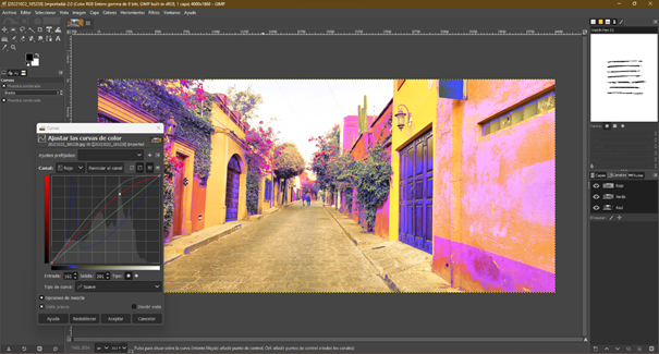
To
illustrate this, I started working with a raster image editor: GIMP. This
software gives you the opportunity to make a lot of modifications to a raster
image, to try this software s capabilities, I followed a few of the tutorials
that are in this webpage: https://www.gimp.org/tutorials/
Here
are some of the results:
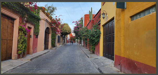
Original
image:
There
are some settings and tools that are suited for beginners like me, such as
cropping, changing the Size of an image or rotating it.
Most
of the other tools are thought for professionals (at least more advanced users)
with functions as Color curves, lighting, and other forms of editing.
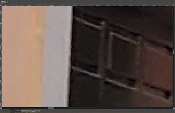
The
most important thing of raster image is that you should know that it is limited
by the pixel size and if you want to resize an image the pixels would become
more apparent as the size goes to the bigger side. For instance, this is a 10x
close up to one of the doors in the above image. You would struggle to find out
what it is if you did not have any context.
The
other image type is vector, it is saved as a .svg
file which stands for scalable vector graphics. This kind of files store the
images through a series of points and lines, this allows the images to be made
as big as you want to without losing quality.
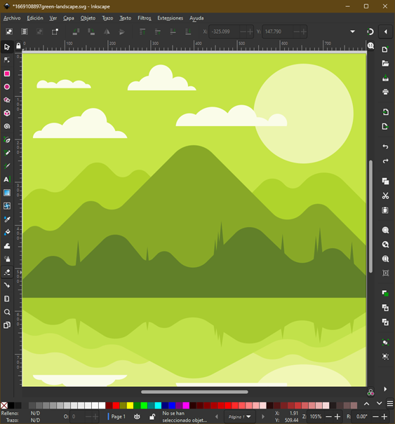
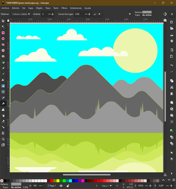
To
work with this, I tried a software called Inkscape which allowed me to explore
the options to modify this type of file, I did not use one of my pictures
because I needed something that was previously vectorized or directly created
with vectors.
I
downloaded a file and followed a few tutorials from the Inkscape official page
to start learning how to take advantage of the vector images:
https://inkscape.org/learn/tutorials/
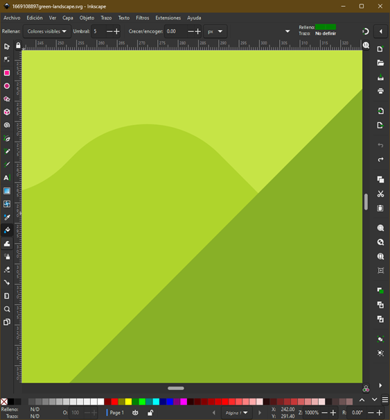
Nevertheless,
the most important part of this is the ability to create larger images from the
same file, as the image is made by lines and points and not from a series of
pixels, the image remains steady as you change the size, you can see it in the
image below with a 10x close up, just like the one I did with the raster image
above.
Conclussions
This assignment importance was to
make a choice for one parametric design software to start working final project
with. My first choice, an open-source software was proving itself more
difficult to use than the Autodesk software. I think this was because I have
some experience using Autocad. For this assignment,
and overall, my project, this is a plausible choice because I have a student
license. Nevertheless, if I must make a choice for a future work software, I
will have to learn how to design in an open-source software.
Original
Files
If you wish to see or download the
files to replicate this assignment, follow the link:
2. Nuevo cubo parametrico v18.iges
Nueval
Checklist
ü
Modelled experimental objects/part of
a possible project in 2D and 3D software
ü
Shown how you did it with
words/images/screenshots
ü
Included your original design files.
2022