

The focus of this week is to design our own PCB board and running AVR program with the board. To do that, we have covered circuit design, components and symbols, PCB CAD software and AVR programming.
The assignment this week is to recreate the Hello World circuit, attaching a LED and a button on the board and running the Hello World program.
Here are the components on this board:
First, I have designed the circuit of the Hello World Board in KiCAD. In the schematics window, add all the components that will need for the hello world board.
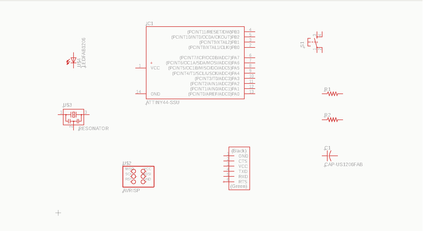
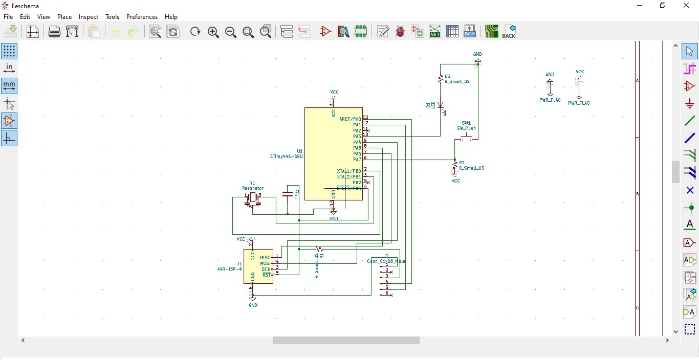
Once all the components and wires are added, here is how it looks like:
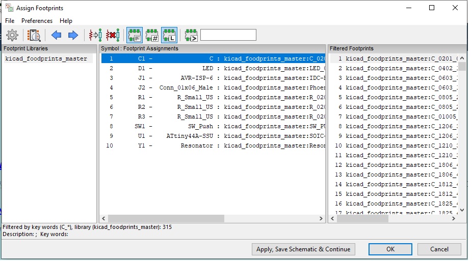
Hereafter need to assign the footprint in to all the components
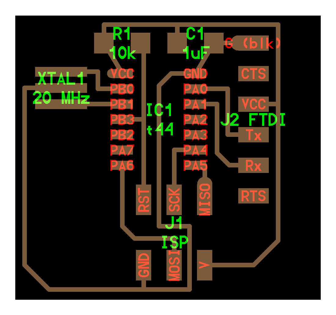
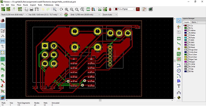
Then, switch the circuit to pcb layout and need to route the traces on the board. The final circuit design is looks like:
The milling of PCB is unable to complete due to the technical issue in SRM-20 machine in our lab. This issue is under processing for fix and once it’s complete I’ll do further.