5.
3D Scanning & Printing
Assignments
group assignment
test the design rules for your 3D printer(s)
individual assignment
design and 3D print an object (small, few cm3, limited by printer time) that could not be made subtractively
3D scan an object (and optionally print it)
Download files
Download all the files from this week's adventure.
Download all filesTable of contents
Test the design rules for your 3D printer(s)
Link to Tue's group documentation
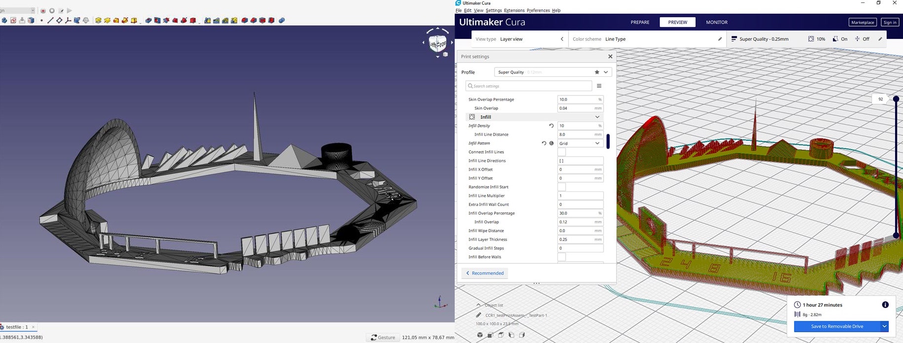
Here it is. Tue printed a benchmark design found here on Thingiverse. She sliced it in Cura using the (relevant) settings seen below.
Settings used for the printing
Layer Height 0.2mm
Print Speed
Infill Speed 60.0 mm/s
Wall Speed 30.0 mm/s
Travel Speed 150.0 mm/s
Wall Thickness 0.8 mm
Wall Line Count 2
Infill Density 10%
Infill Line Distance 8.0 mm

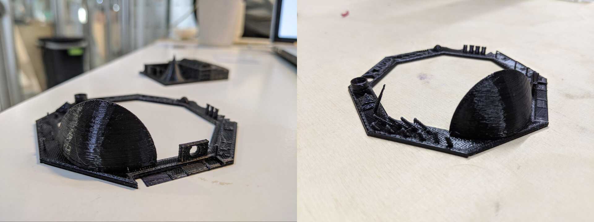
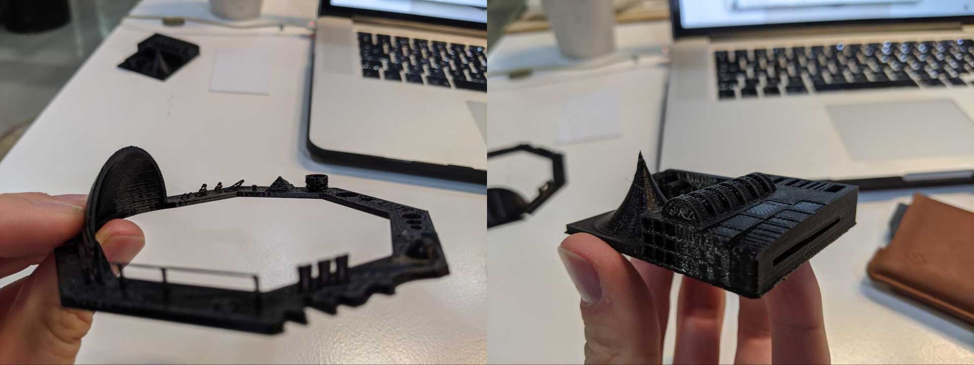
Here is the result of the print.


I played with the settings myself.
Conclusion of the test
Layer Height
When 3D printing the layer height defines the resolution of your print. The smaller the layer height the more detail you get, but at the same time the longer the print takes. You have to find the right balance in between those two.
In our case you can see that there isn't very high level of detail when using a layer height of 0.2mm. The layers are easily distinguishable, and doesn't allow for high precision overhangs and briges. At the same time, a thicker layer height might allow for a more solid bridge / overhang.
Print speed & temperature
You have to be careful with print speed and temperature when it comes to overhangs and bridges.
If the speed is too high there is a higher change of the printer stretchign the filament, therefore making it thinner, and more chance of it to sag down.
If the temperature is too high it takes longer for the filament to cool down and solidy, and therefore once again giving it more change for it to fall.
Accuracy
Some printers have higher accuracy from others, so it is important to test before printing, if your piece needs to fit with other objects.
Scanning in Skanect
I needed a guitar holder for my bedroom, so I decided to scan Bruno’s arms and make a guitar holder out of it.
Using the Fab Lab’s PC we connected the Kinect by Microsoft to the computer and launched Skanect. The interface is pretty easy and straightforward. The only problem was the stability of the program. The Kinect would get detected but then the software froze and vice-versa.
In Skanect there are a few tabs:
Prepare where you select the size of what you will capture (for example Body = 1m³ or Object = 0.6m³). I chose Object as I only needed the arms.
Record where you actually capture the geometry through the Kinect’s technology: IR project and sensor and RGB cameras.
Reconstruct which helps rebuilding the geometry when you are done recording
Process where you make the final tweaks, such as cleaning up
Share where you export and save your file (and optionally can send to Sketchfab)
Capturing the geometry
Recording is straightforward. You have to keep an ideal distance of 1m from the object you are scanning. The bottom screen shows red when the object is too close.
I turned around Bruno’s as he was keeping his arms back. I made sure to go under the arms and far enough at the back. It ended pretty nicely, except the top of the arms that have holes.

Processing the geometry
To clean up the messy scan there are a few simple steps.
First, head to the Move & Crop and get rid of extra geometry needed. I decided to keep everything and edit later in Rhino if needed
Second, go to the Remove Parts. It allows you to delete those floating geometries depending on their size. If they represent less than, let’s say 15% of the geometry, then delete it.
Finally, the geometry is not watertight so let’s head to the Fill Holes tab where you can use different strategies to close the gaps. I used the default Watertight strategy and Medium Smoothing.

Exporting the geometry
In the Share menu there aren’t too many options. Or save the project and come back to it later, or Export the geometry.
I exported the geometry to STL and OBJ extension, to be safe.

Editing the object in Rhinoceros
Cleaning up the model
Now I have the arms, I simply need to import the STL file in Rhinoceros and Boolean Union it with a block to screw it in the wall.
I tried to Split it with a Surface but it didn’t work for some reason.

Actually editing in Blender
As I didn’t seem to be able to split it on Rhinoceros, I tried with Blender. We had a course with Victor about using Blender for 3D printing.
Importing the model
In Blender I clicked Import > Stl (.stl) but I got an error…

Luckily in Skanect I exported the model in .stl and .obj files, and when I imported the .obj file, it worked fine… phew.

Fixing the geometry
When importing it was in the wrong scale, so I scaled it down to something manageable. The space between the two arms support the guitar neck, which is 40mm wide, so let’s scale down to this.

Then I created a few cubes that covers the part of the model that we want to get rid off. I wanted to keep only the arms, so I covered the rest.

Then Boolean Unioned these cubes together, so it becomes one object for the next operation.
While having the model Activated I went to the Modifiers Tab and chose the Boolean Modifier. I kept the Operation as Difference and selected the previous steps’ object as the Object to subtract with.

There are few extra vertices being left over here and there, so deleted them in the Edit Mode page. It isn’t essential as in the end I am adding a block that joins the two arms together to be able to screw the piece in the wall.


Again, this is not essential for the same reason as above, but I was following the tutorial Victor was giving us live.
In Edit Mode use the edge select tool and click on an edge while holding the Cmd key down. That’ll select all edges that create a loop. In this case the model is very messy so it stopped at some point. I simply had to do the same operation while keeping the Shift key pressed to add it to the selection.

Then tapped F to fill the surface that is defined by the Edges.

Finally I created a cube and scaled it here and there to give it a rough shape. Done.

3D Printing
Why it can't be done subtractively
This piece cannot be made subtractively because there overhangs where the arms are.
Slicing with Cura
To 3D print, first you have to slice your file. I used Cura as it is what the lab uses. As I was the last one in the lab I authorised myself the cheekiness of using a layer height of 0.1mm, so the print took quite a while, but I wasn’t there to witness all of it. Nobody was actually.
My settings for this print are below.
Print Speed
Infill Speed 60.0 mm/s
Wall Speed 30.0 mm/s
Travel Speed 150.0 mm/s
Wall Thickness 0.8 mm
Wall Line Count 2
Infill Density 20%
Infill Line Distance 2.0 mm
Infill Pattern Tri-Hexagon
I also decided to use support for the hands, but only at 5% density.
Let’s Save to file on an SD card, head to the Anycubic Kossel Plus printer and set it up.

I chose the Tri-Hexagon infill pattern for its strength, as it will be needed to carry the guitar and not break. We can see the holes for the 3 screws.

You can see the supporting walls here, in blue.
Setting up the Anycubic Kossel Plus
-
As the printer had been used before with the same material (PLA) I didn’t have to change it’s settings.
- I simply pressed on the knob to enter the menu and did Prepare > Preheat PLA
- Into the menu again and select Print from SD card
- Select the file I exported earlier
and there it goes!

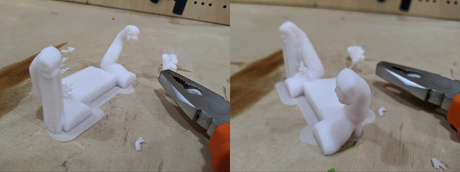
After letting it overnight, here’s the result. I used some claw to break off the supports.
