Electronics Production
Group Assignment
- Characterize the specifications of your PCB production process
Individual assignment
- Make an in-circuit programmer by milling the PCB, then optionally, trying other processes.
Learning outcomes:
- Describe the process of milling, stuffing, debugging, and programming
- Demonstrate correct workflows and identify areas for improvement if required
Have you:
- Shown how you made and programmed the board
- Explained any problems and how you fixed them
- Included a 'hero shot' of your board
Group Assignment
Go to the group assignment page
Individual Assignment
This week I will be making an ISP (In-system programming) or in-circuit programmer.
I chose to do Brian's ISP. I chose it for its simplicity and cost as it is stripped down to a bare minimum of components.
The process will be split in phases: Milling, Stuffing/Populating, Debugging, Programming:
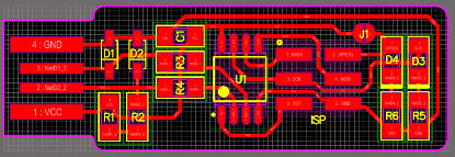
Milling
In this phase I will be using the following:
Fab Modules
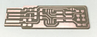
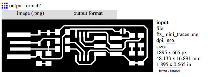
- I started by downloading the Traces (1000 dpi) and Outline Cutout (1000 dpi) of the circuit provided in Brian's tutorial.
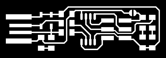

- At Fab Modules
I selected the option "image (.jpg)"
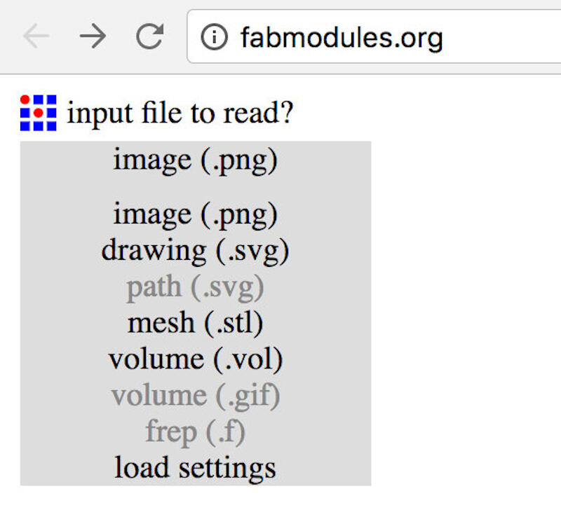
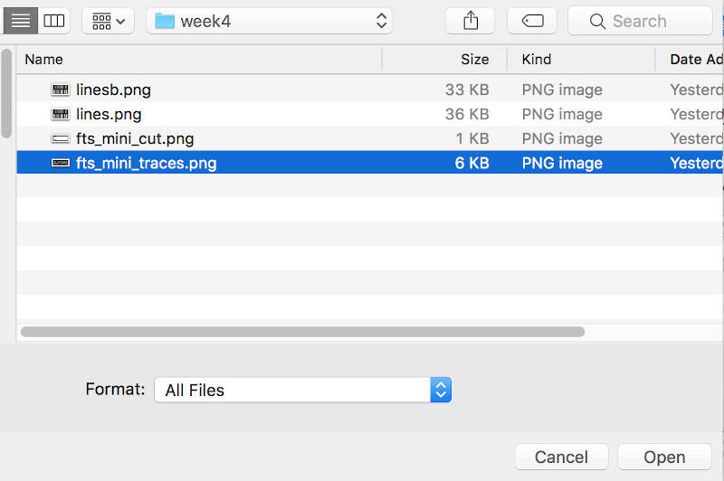
I chose the image file
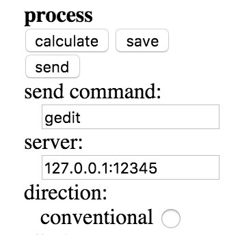
Once the image is loaded, I selected "output format" and then "G-codes (.nc)"
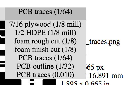
In Process, I selected "PCB traces (1/64)"
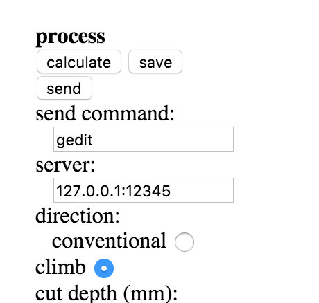
Before calculating, I changed the cut depth to 0.05, half of the default value, as I was being a bit cautious.

Then I pressed calculate
After calculation, I proceeded with an inspection of the tool path to make sure that all traces were covered. By holding the left mouse key, I was able to move the image, and with the wheel button, I could zoom the image to better check the tool path.
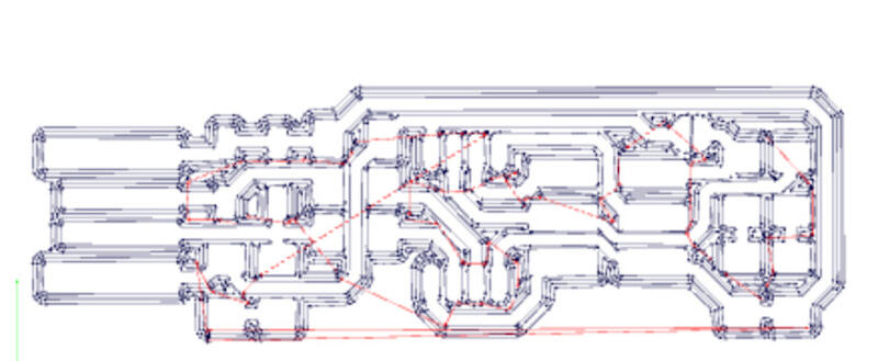
By holding the right mouse key, I was able to even see it with a different perspective.
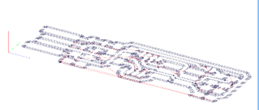
Lastly, I saved the file for the milling process.
To outline, I followed the same steps as before, except I chose "PCB outline (1/32)" instead of traces.

2- Mach3
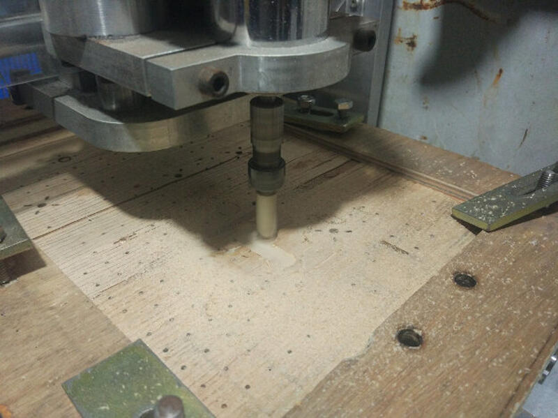
I started the preparation of the CNC by milling a pocket the size of the blank PCB (76x50x1.5mm)
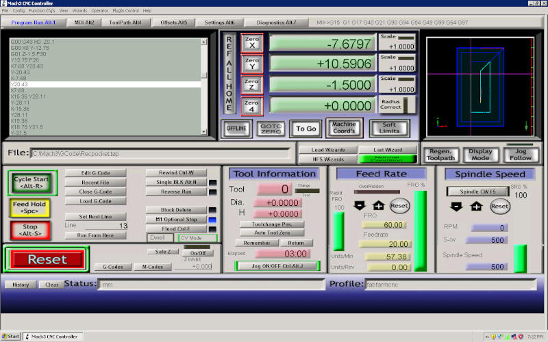
Milling the pocket
Finished pocket
Gluing double-sided tape on the FR1 board
The end result is this.
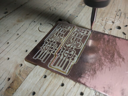
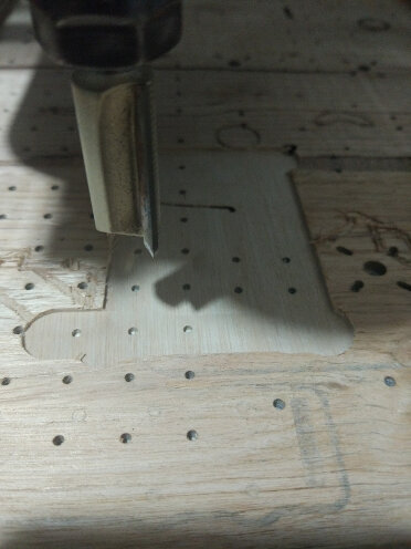
Milling the cutout of one of the ISPs
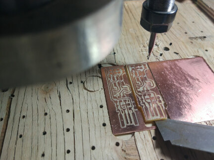
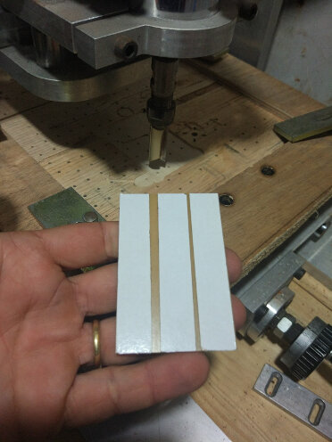
Removing the PCB from the pocket.
I used a blade and sandpaper to remove shavings left from the milling process.
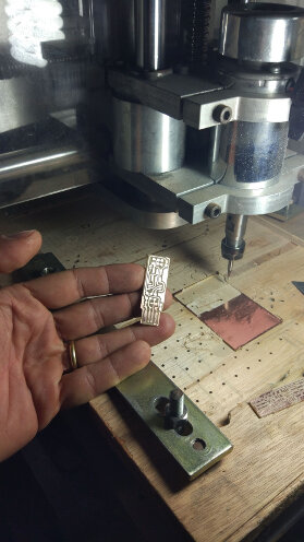
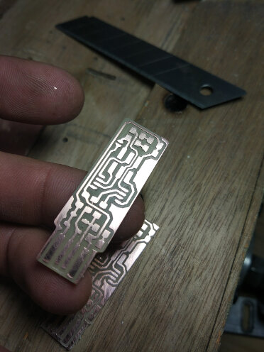
Removed the double-sided tape from behind the PCB.
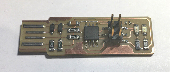
3. Stuffing
Based on Brian's ISP's page tutorial, I started by creating a spreadsheet with the components and their positions.
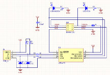
BOM
|
Components |
Location |
Digikey or Mouser Part number |
Manufacture Part # |
|
- ATtiny45 or ATtiny85 |
U1 |
ATTINY45V-10SUR |
|
|
- 2x 1kΩ resistors |
R1, R6 |
RC1206FR-071KL |
|
|
- 2x 499Ω resistors |
R2, R5 |
RC1206FR-07499RL |
|
|
- 2x 49Ω resistors |
R3, R4 |
RC1206FR-0749R9L |
|
|
- 2x 3.3v zener diodes |
D1, D2 |
BZT52C3V3-7-F |
|
|
- 1x red LED |
D4 |
LTST-C150CKT |
|
|
- 1x green LED |
D3 |
LTST-C230TBKT |
|
|
- 1x 100nF/0.1uF capacitor |
C1 |
C1206C104KARACTU |
|
|
- 1x 2x3 pin header |
ISP |
71600-006LF |
After that, I proceeded to solder all components in place.
3- Pre-Debugging
I started with a visual inspection.
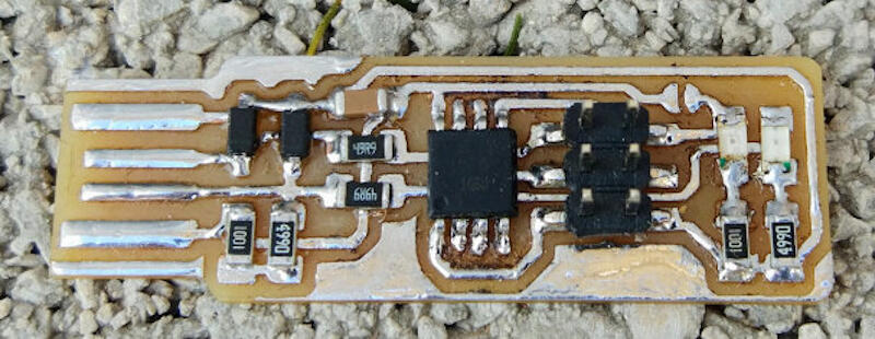
OK, I need to clean a bit more.
With the multimeter, I looked for shorts and nothing was detected, especially between Vcc and GND.
Overall, the board seemed fine, so I proceeded with the programming.
4- Programming
In order to program the fabricated programmer, I made use of a hardware called UsbASP. Extracted from Thomas Fischl's website, he describes it as:
"USBasp is a USB in-circuit programmer for Atmel AVR controllers. It simply consists of an ATMega88 or an ATMega8 and a couple of passive components. The programmer uses a firmware-only USB driver, no special USB controller is needed."
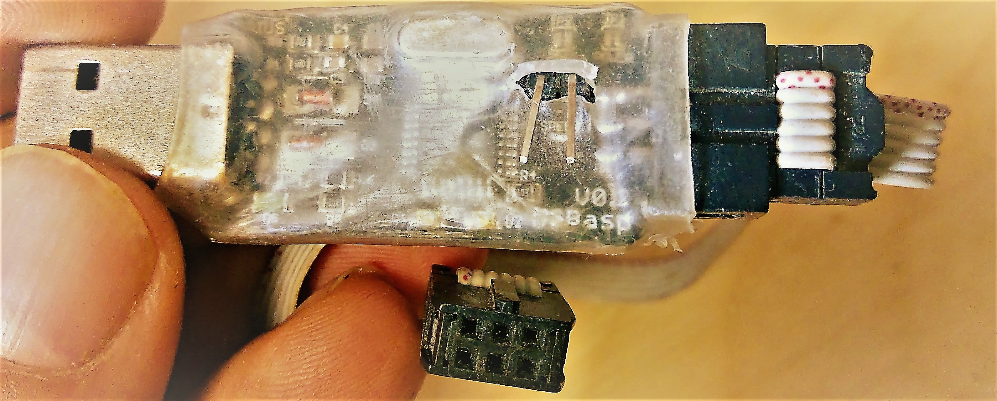
You use it just like the tinyUSB.
The header poking out of the transparent plastic cover is to program at 8 or 16 MHz. The USBasp I have does not detect speeds automatically, so simply install a jumper to change speed modes. This is necessary, for example, when programming the ATTINY44 or 45 (slower speeds) while with an IC like the AT90USB1286, it can be programmed at 16 MHz. The new firmware on these programmers usually can detect the speed of the chip automatically, like the ones sold today at Aliexpress for less than 2 dollars.
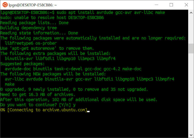
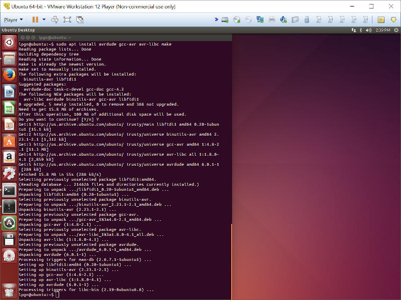
So going back to the software, under Ubuntu for Windows 10 (Linux Windows Subsystem), I started by installing the programming environment with the code sudo apt-get install avrdude gcc-avr avr-libc make
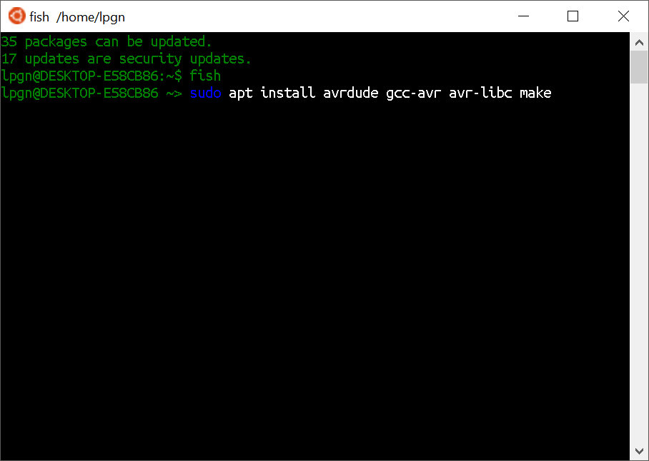
With the prior command, the programs got downloaded.
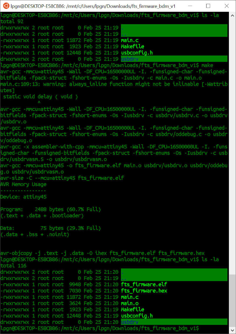
I then downloaded the firmware source to a directory. Following that, I ran the command make
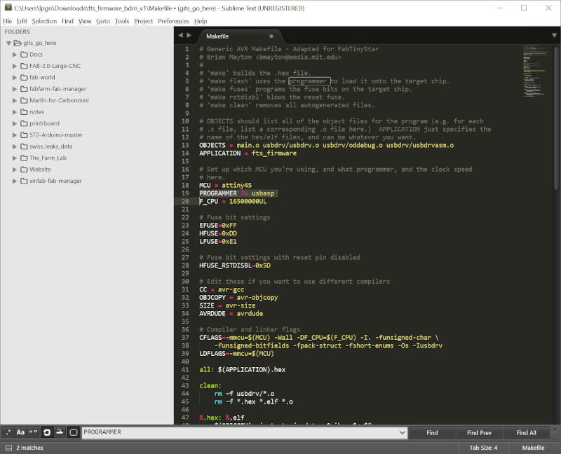
Using Sublime Text, I edited the makefile file and replaced the entry "PROGRAMMER ?= usbtiny" with "PROGRAMMER ?= usbasp".
As explained before, making a USBtiny, I did not have a programmer other than the USBasp, so that's why I replaced the code with the one compatible with my device.
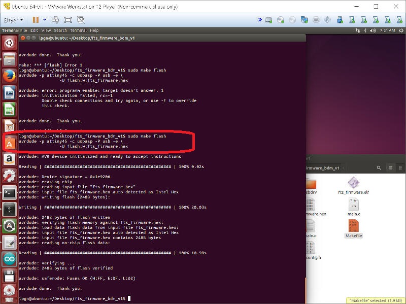
I then ran
make flash
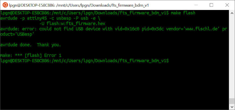
But no success. So I ran lsusb to get the list of available USB devices.
And I got a message "unable to initialize libusb: -99"
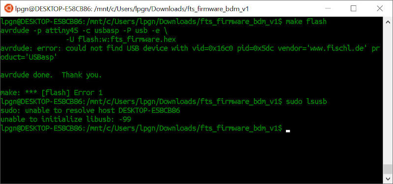
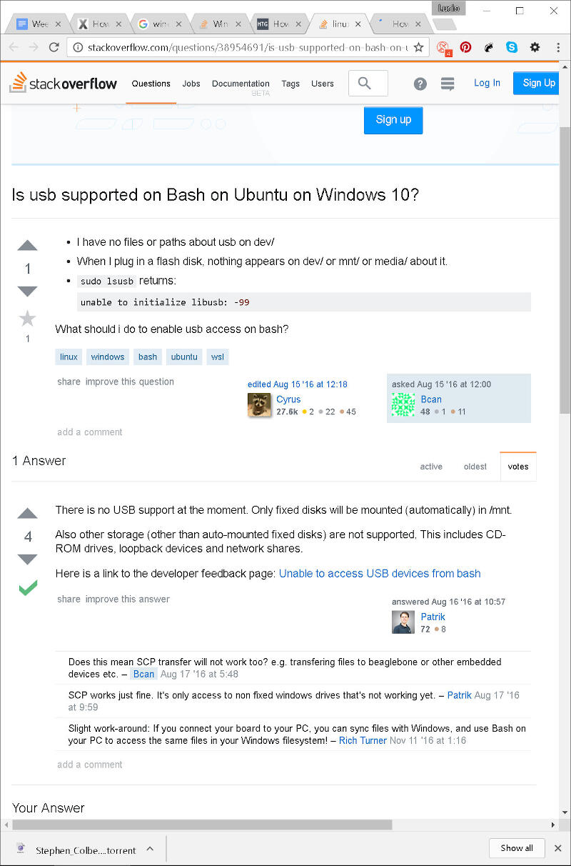
After a quick search on Stack Overflow, I found out there is no support for USB under Windows 10 Ubuntu shell yet! Argh!
Note: I haven't confirmed yet, but apparently in 2020, USB is supported in Windows Linux Subsystem OS, but not at the time of making these exercises.
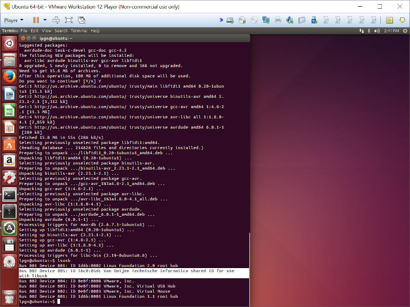
Then I gave up on Ubuntu Bash for Windows 10 and ran a copy of Ubuntu under VMware Player. At Ubuntu, I ran:
sudo apt install avrdude gcc-avr avr-libc make
This time, after running lsusb, I could see that the device is present.
I ran
make
in order to compile the firmware.
I then ran
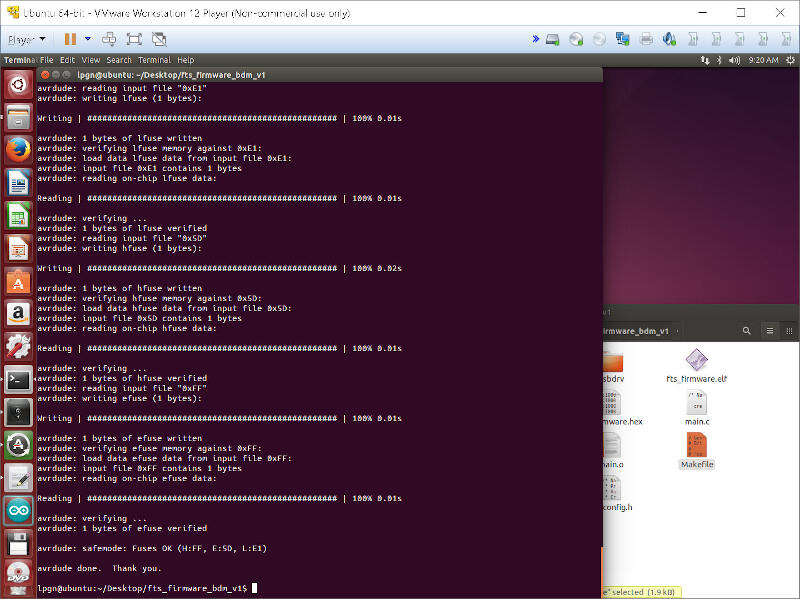
make flash
But again, I got an error message.
I realized that Brian's ISP has to have a jumper installed in order to program the ATtiny45, and yes, I forgot to solder the jumper.
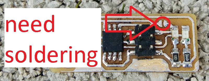
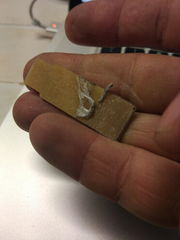
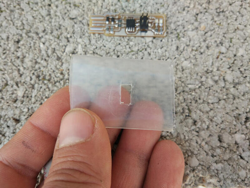
That made me remove the shrink tube I had installed prior.
So I did it!
And it works!
Next, I ran
make fuses
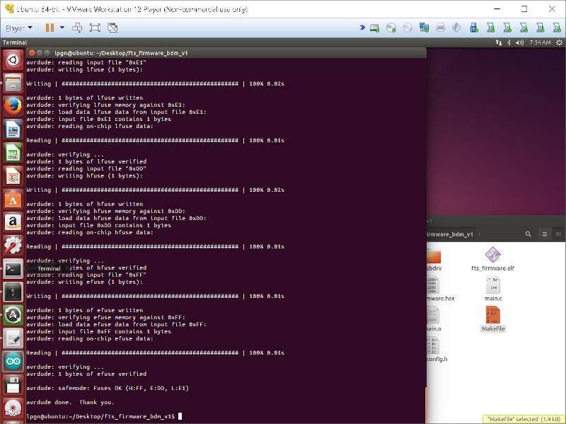
After having the firmware uploaded and fuses burned, my new ASP would not be recognized.
So back to debugging…
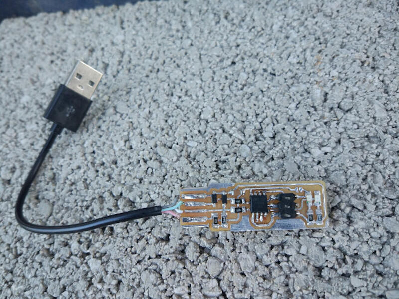
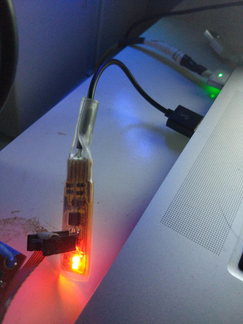
I ended up measuring each resistor value and replacing the ATtiny with a new one. With a multimeter, I found out that the R1 1K resistor was not working. I replaced it, and voila! Board detected!!! Oh, also, I decided to install a USB connector I cut from an old cable, and after some washing, that's how it looks.
Final command make rstdisbl
It worked! Now I remove the jumper!
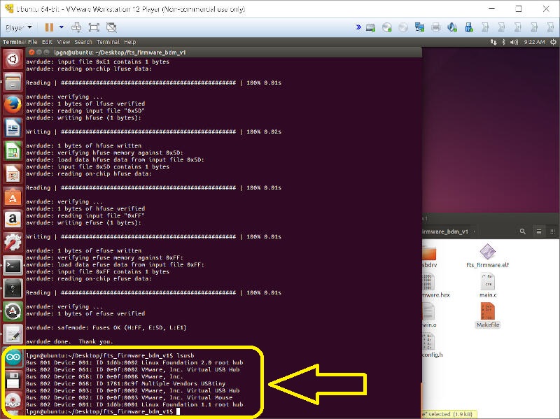
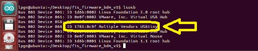
It works! That is proved by the detection of the USBtiny by the Linux command lsusb as shown in the picture above and zoomed below:
5- Final Test
Not tired of changing platforms, I decided to test Windows. Here I print how I load the driver for my USBasp. I use this very useful software that makes installing drivers on Windows 10 less traumatic.
Loading the driver on Windows, I use the tool "Zadig_2.2.exe"
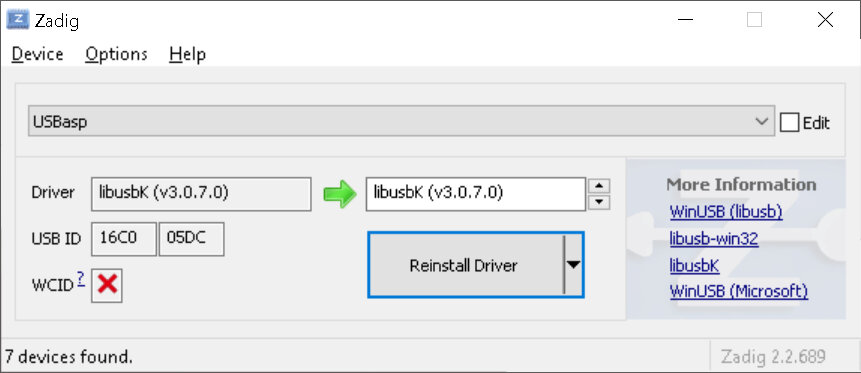
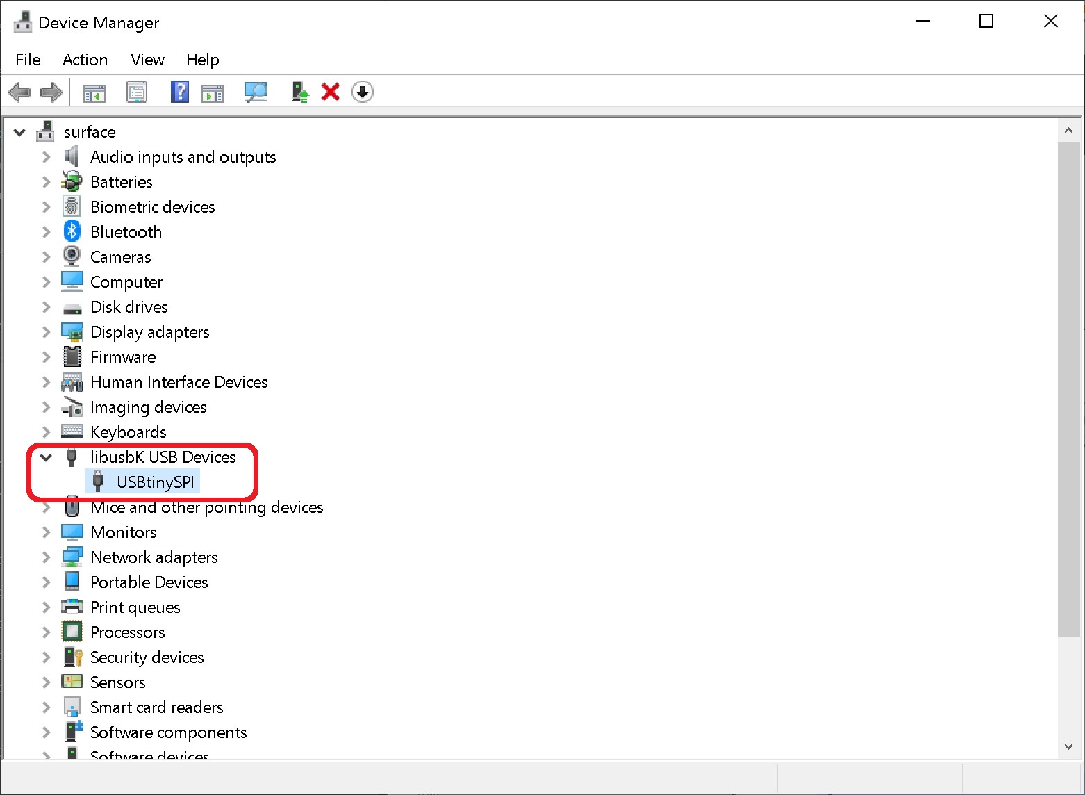
Here I show a recent print that proves the USBtiny is detected under Windows. Since I have done this exercise years ago, I do not have the driver installation procedure outlined for Windows, but I have shown its detection before on Linux as well as now on Windows.
After the driver installation, I tested under Windows the burning of my 3D printer board's firmware. The firmware I burned, as just outlined, was the firmware for a Printrboard I made years ago with the open-source plans.
In the terrible footage below, you can see this happening with the code avrdude -c usbtiny -p at90usb1286 -U flash:w:BootloaderHID.hex:i -U lfuse:w:0xDE:m -U hfuse:w:0xdb:m -U efuse:w:0xF0:m
To eliminate confusion about whether the fabricated USBtiny burns or not, let's dissect the code above:
- The first part
avrdudeis the name of the program. - Then
-c usbtinydefines the programmer name, "usbtiny" is the fabricated programmer name. - Next
-p at90usb1286is the target IC to be programmed, here the AT90USB1286 that is installed on my Printrboard. -
-U flash:w:BootloaderHID.hex:idefines the name/location of the firmware to be loaded, in this case "BootloaderHID.hex". -U lfuse:w:0xDE:m -U hfuse:w:0xdb:m -U efuse:w:0xF0:mis the part of the command that burns the fuses.
The above-mentioned is shown in the terrible footage ;-) below
All working!