6. 3D Scanning and printing
This week the group assignment is to test the design rules for our 3D printers. And the individual assignment is to design and 3D print an object (small, few cm3, limited by printer time) that could not be made subtractively. In addition we have to 3D scan an object (and optionally print it).
Files, planning and tools
Files
- Leaf for 3D print
- Voronoi leaf
- Chinese Lantern
- Scanned branch with leaves
- Scanned files
- 3D printer test
- STL files of Branch and Lantern
Planning
- Test the design rules of one of our printer
- Compare the test of the different printers
- Learn how the Sense scanner works and scan something
- Try out some 3D-scan apps and scan something outside
- Create a 3D design
- 3D print my design
- Get an understanding of the difference between subtractive and additive
Tools
- Prusa Prusa i3 M3
- Ultimaker 3
- Ultimaker 2+
- uPrint
- Sense scanner
- Qlone scan app
- Trnio scan app
- Blender
- Fushion 360
- Dimension
- Cura
- Wave wash support cleaning system
- Voronoi script
Link with final project
This week I want link this assignment to my final project spiral experiments which related to the shape of my project. My first goal is to create a leaf as this is the basic shape of my final project. However a leaf can also be made subtractively therefore it would fit the assignment. Therefore I would like to see if I can include a tree like shape in my design as well.
Research and inspiration
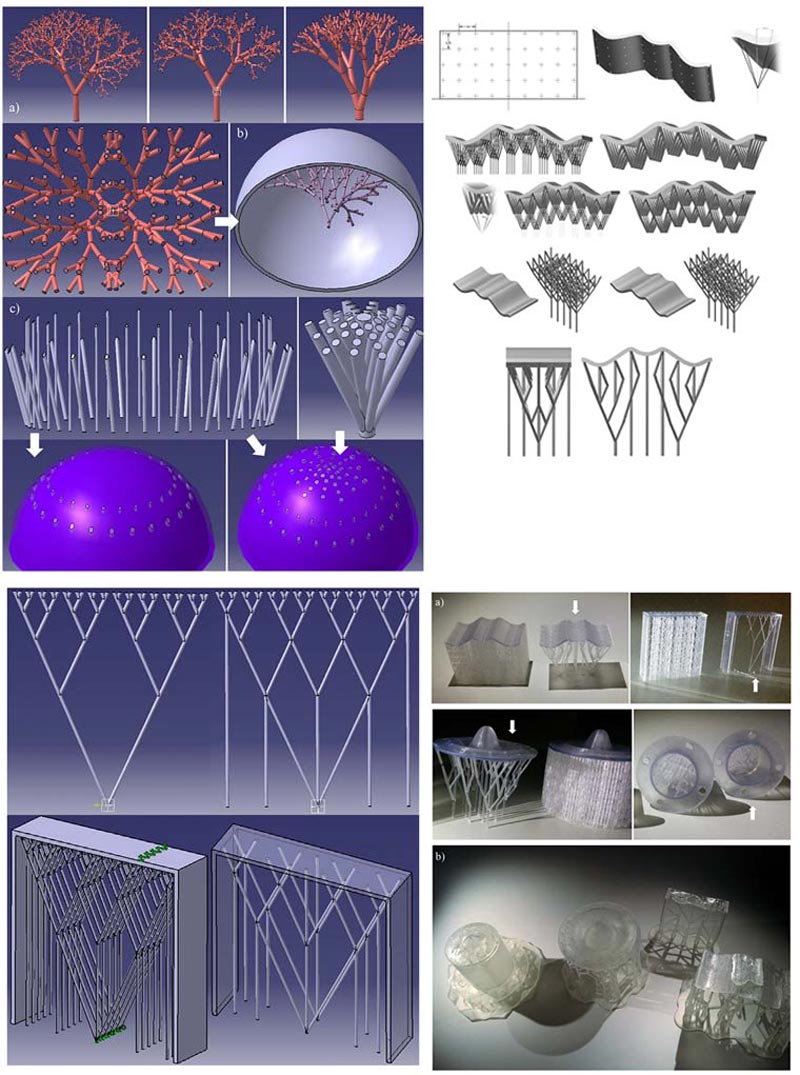 “Design and Performance Assessment of Innovative Eco-Efficient Support Structures for Additive Manufacturing by Photopoymerization” (Lantada et al., 2017)
As I though a leaf on its own would not fit the assignment I research more about additive design and I found an interesting article on “Design and Performance Assessment of Innovative Eco-Efficient Support Structures for Additive Manufacturing by Photopoymerization” written by (Lantada et al., 2017). In this article Lantada et al. describe how they design the support of the design as well, in their case to make it more Eco-efficient. In my case I want to see if I can use this to create a additive design where I combine my leaf with fractal trees.
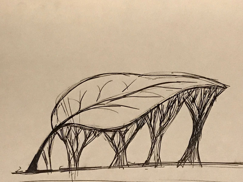 I first made a sketch of the idea I had inspired by this article
links used for Fushion
- Cura
- Modifying a High Poly STL in Fusion 360 by Desktop Makes(2017)
- “Test your 3D printer! v3” file by ctrlV
- Autodesk Fusion 360 - Using Voronoi Sketch Generator by Travis Davids
- Voronoi sketch generator - 3d printed sheet metal lamp - fusion 360 tutorial
- Fusion360 Voronoi script by Hans Kellner
- How to install an ADD-IN and Script in Fusion 360? -fractal tree generator by AutoCad
links used for Blender
- Blender
- Blender Essential Training by Lynda
- How to Create Branches and Leaves in Blender by Computer Clan
- Blender Grow Kit
What we did – Group assignment step-by-step
First we had to calibrate and compare the printers at the Waag Fab Lab. I worked together with Taco, who works at the Waag and joins our classes because he wants to learn how the machines work. I wanted to test the Prusa i3 MK3 because I’m already used to the Ultimaker and I was curious how this printer would work and what kind of quality it would have.
Step 1: prepare the file with Cura
As a group we decided to use the file “Test your 3D printer! v3” by ctrlV on Thingiverse. We all used the same file so we could compare the end result of the three 3D-printers at the Waag with each other.
We used Cura to set up the print file and generate a gcode that can be used in the 3D-printer. Taco and I decided that we would also like to test what the influence of the layer height would be on the end result. We wanted to test three different versions: 0.6, 0.4 and 0.15. However due to a lot of trouble shooting we only managed to print the 0.15 version.
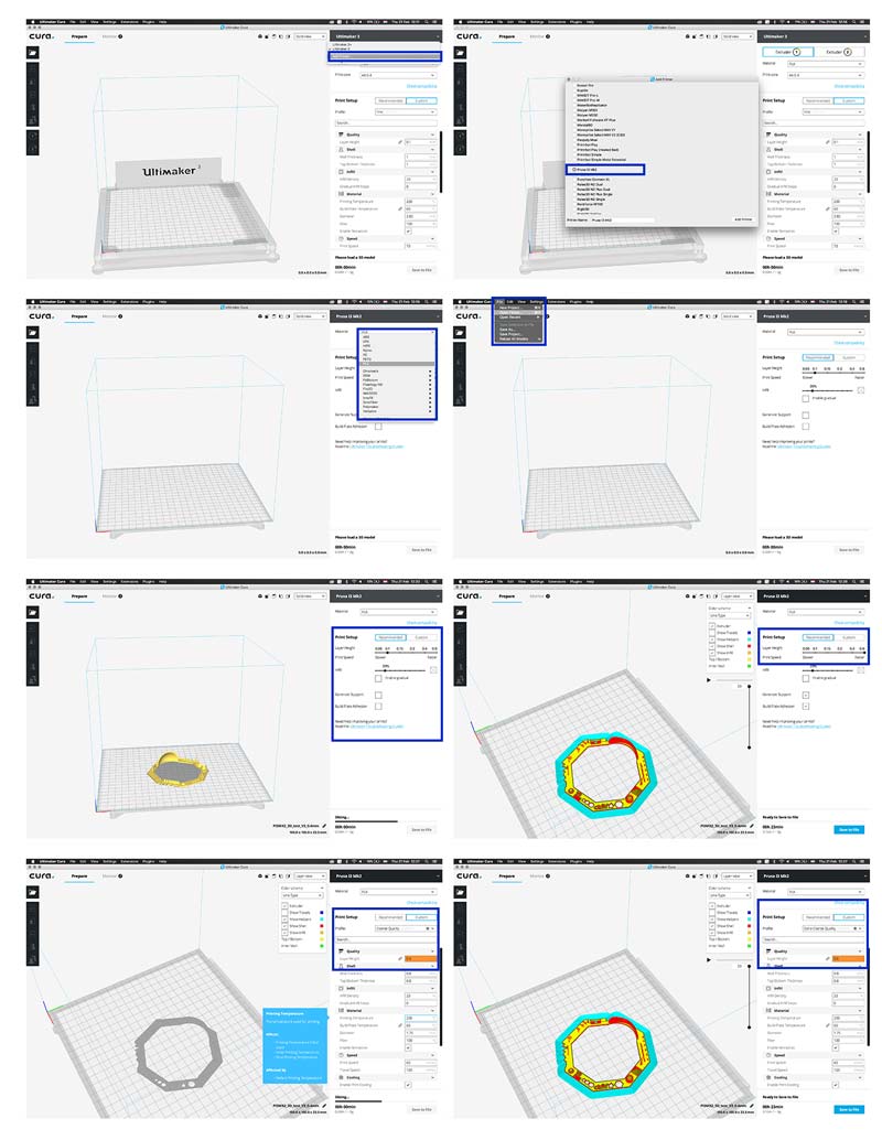 Preparing our file in Cura
- Open Cura > add printer > select the Prusa i3 MK3 from the list. We select the MK2 because Cura is not updated yet with the MK3 but it should work the same.
- Select material > PLA. We use PLA for this print.
- Recommended settings > Often it’s best to keep the recommended settings as those often work the best. However when you want to experiment with different qualities and settings you can select the custom settings in Cura.
- Custom settings> we selected the 0.6 and 0.4 layer height because we first wanted to test what the difference would be in quality and how far we could stretch the material.
- Once all the settings are the way you want press ‘save to file’ and save the file on the SD-card. This is needed to get the file on the Prusa.
Step 2: prepare the Prusa i3 MK3
After we prepared the file we went to the Prusa i3 M3 to set up the machine for printing. We had a struggle setting up and preparing the printer. First we thought it was due to the change of material. However in the end it turned out to be the cleaning of the bed. More details on the trouble shooting can be found in the “what we did wrong section”.
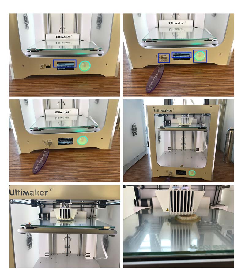
How to unload and load material
First we wanted to change material, to find out how to switch filament on the Prusa.
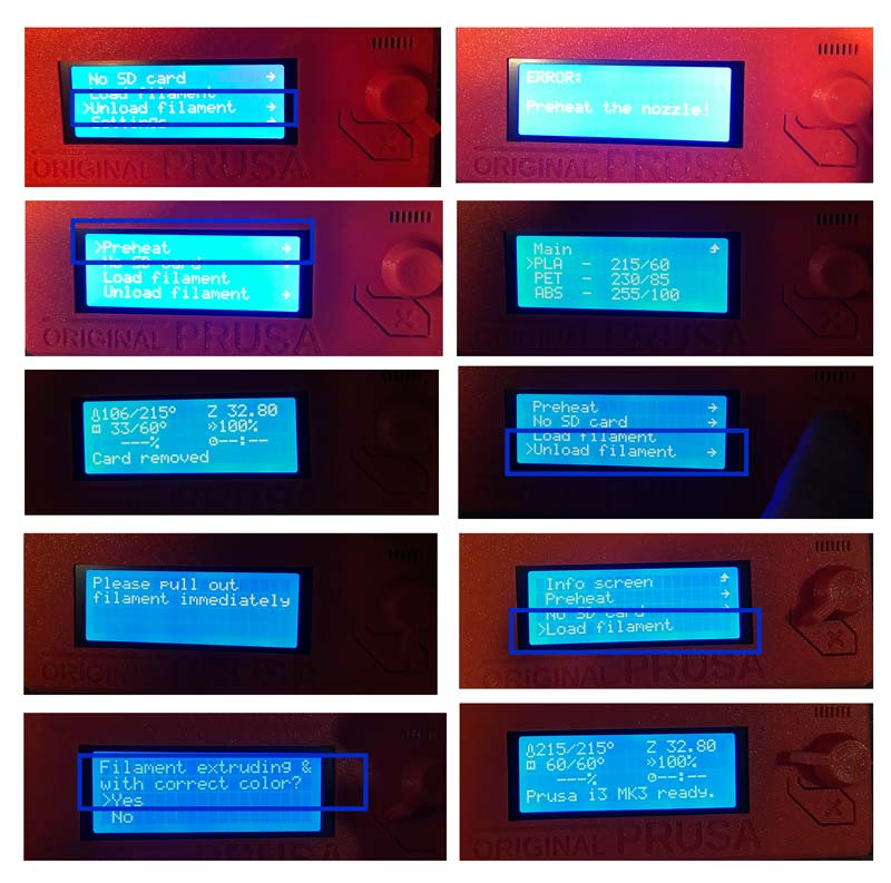 Unload filament on the Prusa
- Go to unload material
- Error message: preheat
- Go back > select preheat > select PLA
- The Prusa is now preheating till it’s at the right temperature for PLA.
- When it’s at the right temperature it is possible to remove the filament. So remove the filament.
- Change spool.
- Select load filament > follow the instructions on the screen.
- When the right material is coming out you know everything is set. The machine tells you as well. Now we can print.
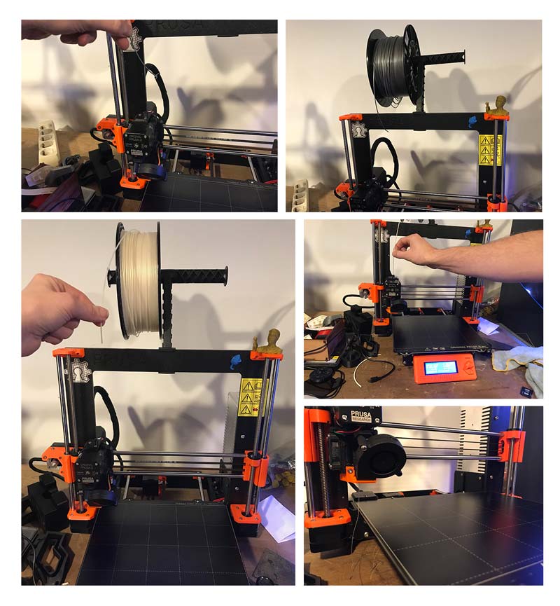 Unload filament on the Prusa in pictures
In the end we changed the material back to the gray because we had a lot of problems when we started to print.
How to calibrate the Prusa
Because our ‘first layer calibration tests’ gave messy results we decided to do a full xyz-calibration. We followed this process two times with still messy results in the ‘first layer calibration test’.
 XYZ-calibration on the Prusa in pictures
- Go to calibrate
- select ‘xyz-calibration’
- follow the instructions on the screen
- For each corner use a piece of paper for the calibration (the Prusa also mentions this)
- It checks all the corners, all the nine points
- When it’s done you still need to adjust the z-axis move it to about -560 for the right distance between nozzle and bed.
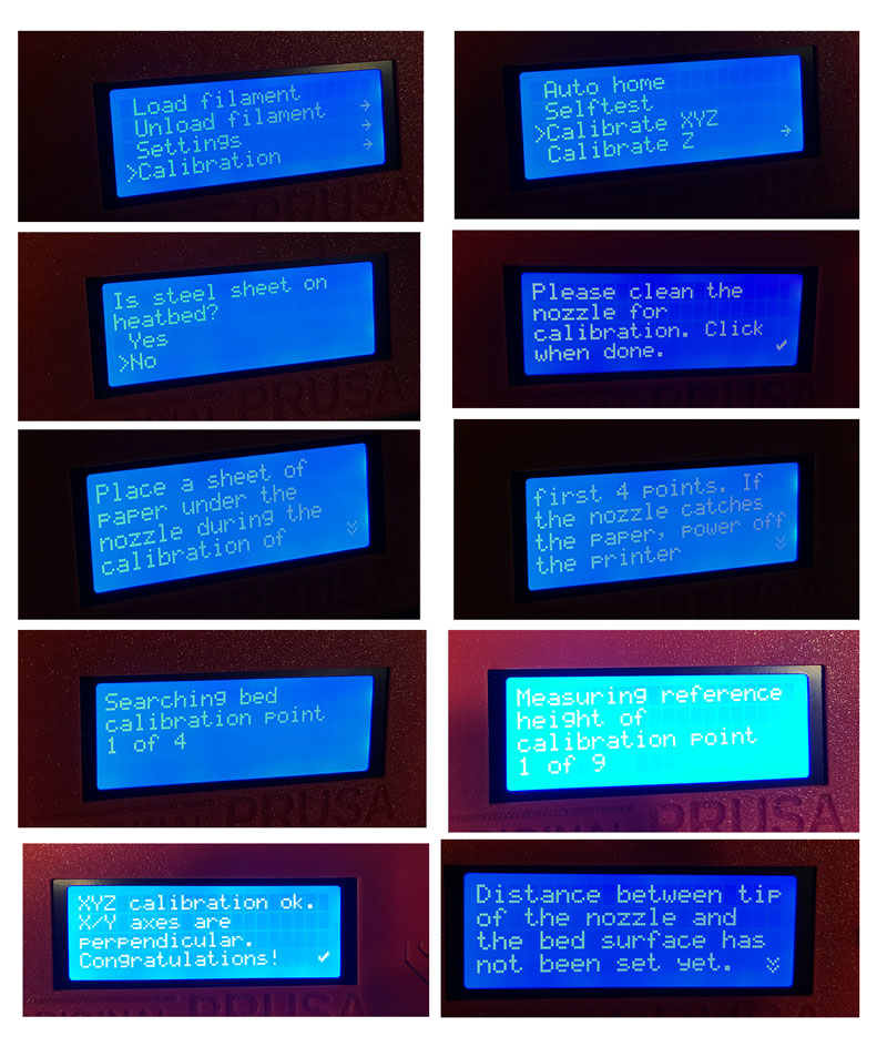 XYZ-calibration steps in Prusa, follow the steps given by the machine
Step 3: compare the end results with the other printers
After we found the mistake with the bed cleaning and we realized the adhesion of the first layer was the problem, we were able to print our test file. This went smooth and fast. It took and hour and fifteen minutes.
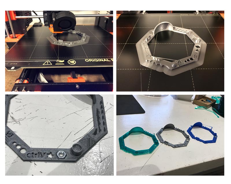 Prusa end result test file
When our print was finished we compared the end result with the result of the two other groups.
- Grey print: Prusa i3 MK3 with a 0.4 mm nozzle and 1.75 mm filament
- Green print: Ultimaker 2 with a 0.6 mm nozzle and 2.85 mm filament
- Blue print: PrinterBot with a 0.4 mm nozzle and 1.75 mm filament
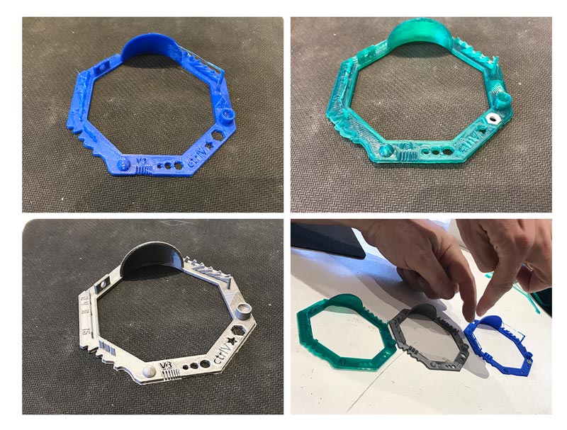 Group end result test file
When you compare the three the print from the Prusa is more detailed and refined than the others it was also one of the fastest. However it’s difficult to compare this version to the one from the Ultimaker as the Ultimaker used thicker filament and a different size nozzle.
What I did – step-by-step
My focus and goal of this week was mainly to get more familiar with 3D design. I iterated my design a couple of times to get more used to Fushion 360 and to the idea behind 3D. I still notice that I don’t use the time line as much as I should,which made my file fairly heavy to process. In the end I designed 5 different 3D-files and I printed 4 object.
First I printed my main the design: the Chinese lantern plant, I used the uPrint for the real size version and the Ultimaker 3 for the smaller version. When I send the file to Cura I realized I didn’t pay attention to the size of my design. To get a better understanding of the difference I printed two versions
While the uPrint and Ultimaker 3 were busy and started the Ultimaker 2+ to print my 3D-scanned file: the branch with two designed leaves added on. For this print I experimented with different sorts of filament.
Step 0: Using Blender
Because I wanted to try out different 3D program I started to research and look into Blender. As Rutger mentioned and I noticed after research that Blender is better or easier to use with organic forms than Fushion. So I installed Blender and looked at different tutorials related to creating trees or a leaves in Blender, like How to Create Branches and Leaves in Blender by Computer Clan. My mind was a bit dazzled as there are lot of tree-related tutorials for Blender because it is used for 3D-modeling in films and animation and in the end I wasn’t sure if this would be useful for 3D-printing as I’m not sure if this creates solids that are easy to print. Time wise I decided that I rather use my time to get more familiar with Fushion 360, as I’m new to that program as well. Maybe if I have time in the future I will try out the Lynda training program for Blender
Step 1: 3D design
With 3D printing I am familiar with the Ultimaker 2, 2+ and 3. I really like the Ultimaker 3 because you can print with two materials. It’s especially nice to use PVA, which is water soluble, as support material. I helped a lot of students how to use the 3D printer but always with their design never my own. Therefore my focus this week was on the design of a 3D object related to my final project.
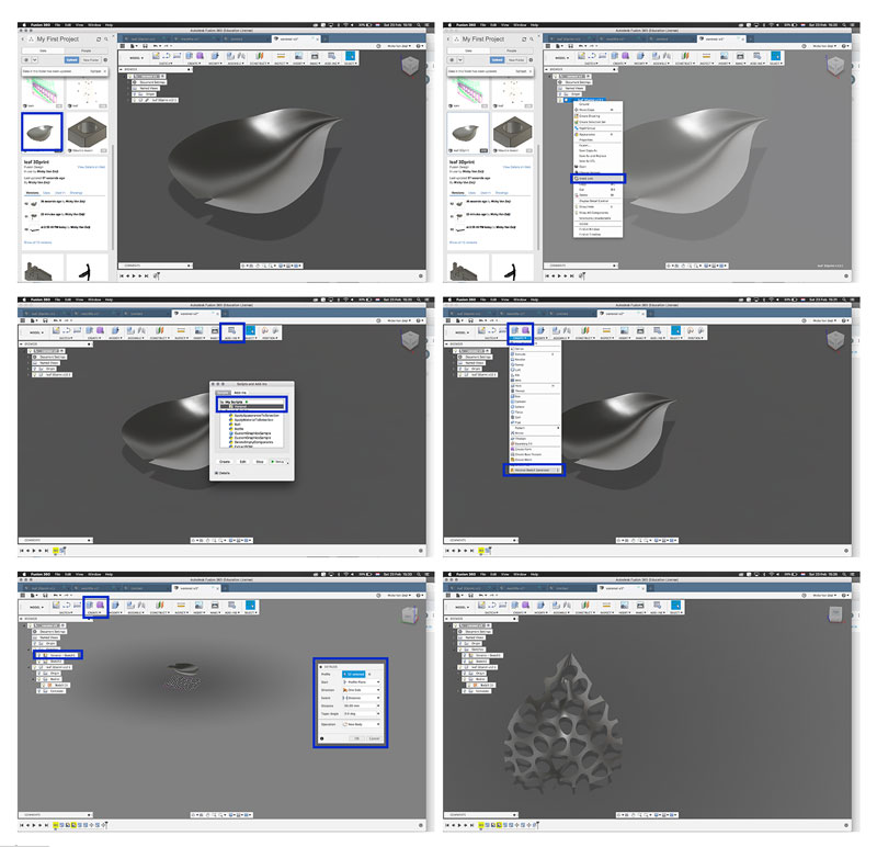
Design 1: a leaf
My first idea was to design a leaf in the skulpt mode of Fushion 360. I designed a parametric version of a leaf in week 4 but this time I wanted to make a more organic shape and use skulpt mode. The images and description show the steps I took:
- Go to Create > select create form
- Select plane > I experimented with the plane function till I got the plane I wanted > 5 in width and 2 in length.
- Go to edit form > I moved the dots around till the plane looks like a leaf in 2D
- After I had a 2D shape I liked I move the dots in the z-axis to make it 3D.
- Go to create > select thicken > I thickened the leaf symmetrical with 0.2 mm. It gave an error when I added more thickness.
- Next step was to create the twig in the sculpt mode.
- Create form > select box > this was more difficult than the plane function. I added and removed edges until I had the shape I wanted.
- Next step is to combine the leaf and the twig. Go to Modify > select combine > select both bodies and combine.
- Right click on the new body and click ‘save as stl’
- I opened this stl-file in Cura to find out how the support would turn out. But the object was really small. So I changed the scale of the leaf and checked the support.
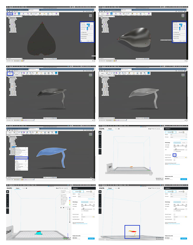 Design 1: leaf
Design 2: fractal trees as support
The leaf I designed does not fit the requirements for this weeks assignment which is to design and 3D print an object that could not be made subtractively. This was not the case with only a leaf therefore my next step was to design the support in the shape of fractal trees. This would give it an additive manufacturing process because it creates more in between spaces. At least that was the idea I had about it.
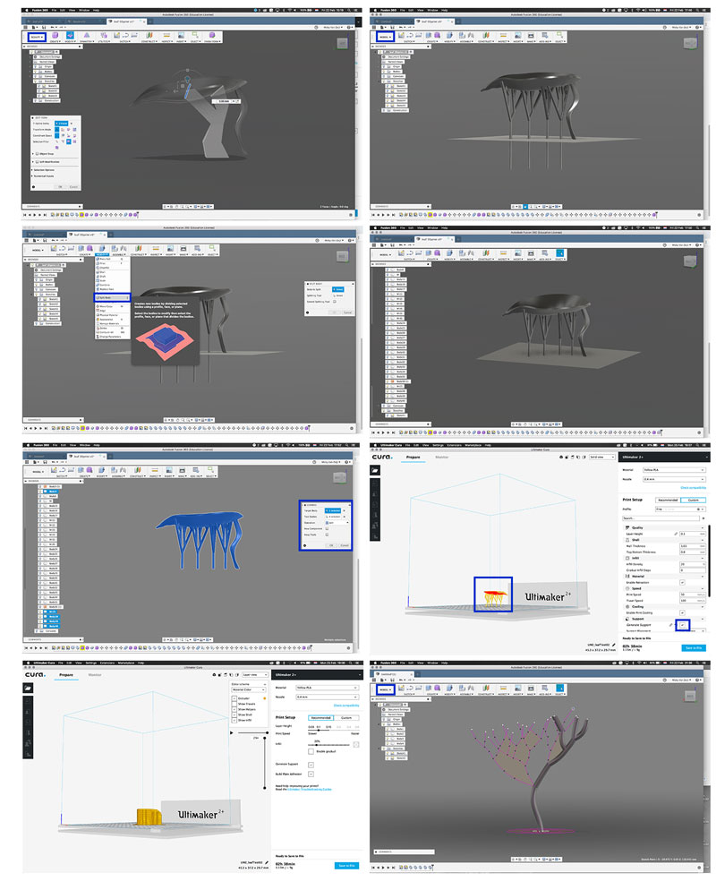 Design 2: leaf with trees
- First I started in skulpt mode but this didn’t work to create the fractal tree. I went back to Model mode. I thought it should be possible to generate a tree as fractals are a mathematical principle. I did find the fractal tree generator by AutoCad but this only worked on windows. In the end I decided to designed the tree by hand.
- Go back to Model Mode > new sketch > select vertical plane
- Select line tool > With the line tool I drew a tree based on the fractal principles.
- Add a new sketch > select horizontal plane
- Draw a circle with the truck as the mid point at the center of the circle.
- Finish sketch
- Go to Create > Sweep > select the circle as profile and the branches as lines.
- I did step 6 for all the branches
- Modify > combine. I combined all the branches into one tree.
- Select tree press ‘m’ > copy > move the copied tree on the right place below the leaf.
- After I had four trees I save the file as stl-file to check in cura if this would work with the support the way I imagined. It turned out it didn’t.
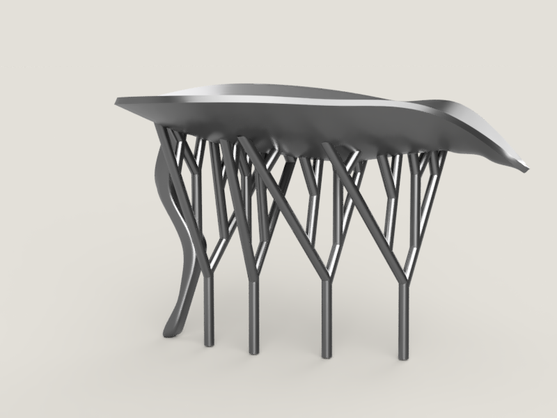 Design 2: end result leaf supported by trees
While I tested my design in Cura I thought again about the difference between additive and subtractive design. And I realized that this version can also to be made subtractive because it doesn’t really have difficult angles, holes, or inside connections and mechanics. It might be more difficult that a tree and delicate when its small but in the end I think this design doesn’t fit the requirements of this weeks assignment.
Design 3: Voronoi diagram leaf
So I started from an new angle and I used the idea behind the Voronoi diagram. Because I thought this pattern, at least if placed on the outer shell of a 3D object which makes it hollow, is for sure an additive manufacturing process.
Therefore my main goal was to use Voronoi diagram to create a pattern for the outer shell. But I still wanted to use the design of my leaf and combine it with my final project iterations. I talked about it with my friend Annemieke and she had a very good suggestion. The Voronoi pattern and the design of the leaf made her think of the Chinese Lantern plant (Physalis Alkekengi). I used her idea as inspiration for my next iteration.
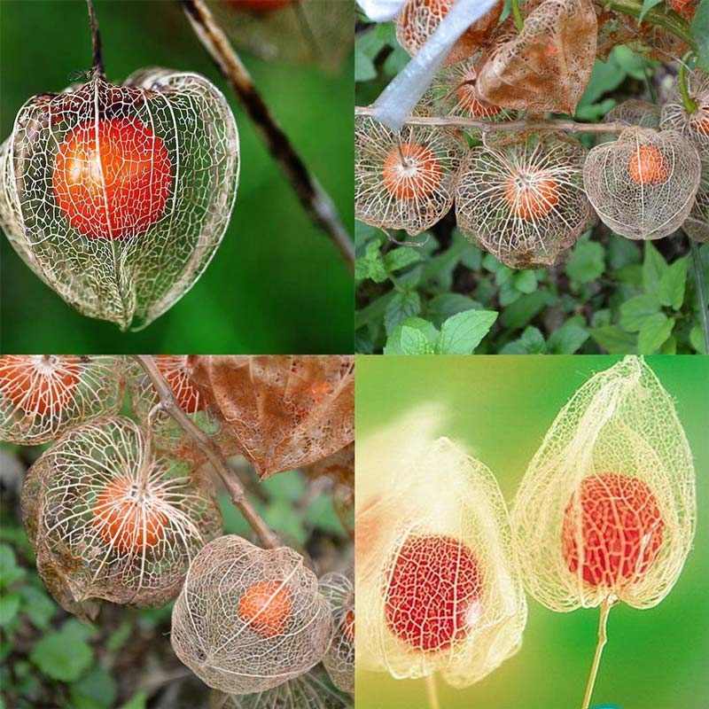 Physalis Alkekengi or ‘Chinese lantern’
How to install voronoi script in Fushion 360
I researched how to use the Voronoi Diagram in Fushion 360 and I found that there is an app in the Autodesk app store that you can use to generate a pattern, but somehow this app didn’t want to install when I downloaded it and started the installer. Together with Annemieke I looked into this problem and figured out that we could download the script on git hub. So we followed the instructions on the Autodesk website how to install the script and I used different tutorial to get it to work. In the end it was easier than I thought it would be.
- Download zip at git hub: Fusion360 Voronoi script by Hans Kellner
- Follow the readme file and the Autodesk tutorial: How to install an ADD-IN and Script in Fusion 360?
- Copy the right file from the zip folder and paste it in the right folder.
- Restart Fushion 360.
- Go to add-ins > click on it.
- Pop-up opens and click on My scripts > Voronoi > Run.
- Now go to Create > and click on Voronoi Sketch Generator
- I first follow some tutorials from Youtube, like: Autodesk Fusion 360 - Using Voronoi Sketch Generator by Travis Davids and Voronoi sketch generator - 3D printed sheet metal lamp - fusion 360 tutorial before I started my own design.
- I used the design of the leaf > Voronoi sketch generator
- Default settings > OK
- Move the Voronoi sketch in line with the design of the leaf, use ‘m’ from move for this
- Create > Extrude
- Extrude > Intersect option > extrude the Voronoi sketch over the design. And now the leaf had a Voronoi pattern on it.
 Design 3: leaf test with vonoroi script
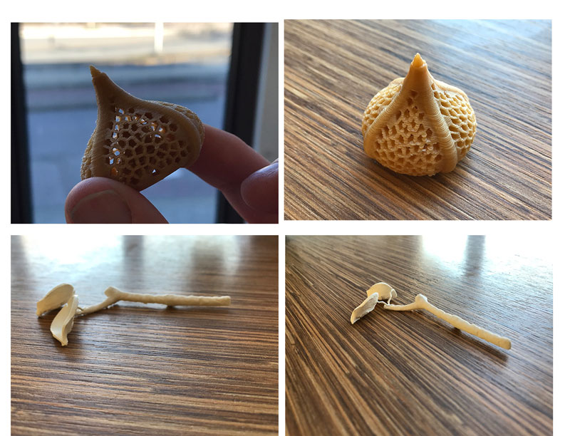
Design 4: Chinese lantern plant
After I installed the script and worked on a test file I started to design my new idea; a dried out Chinese lantern plant. I followed the same steps for the Voronoi pattern as described above.
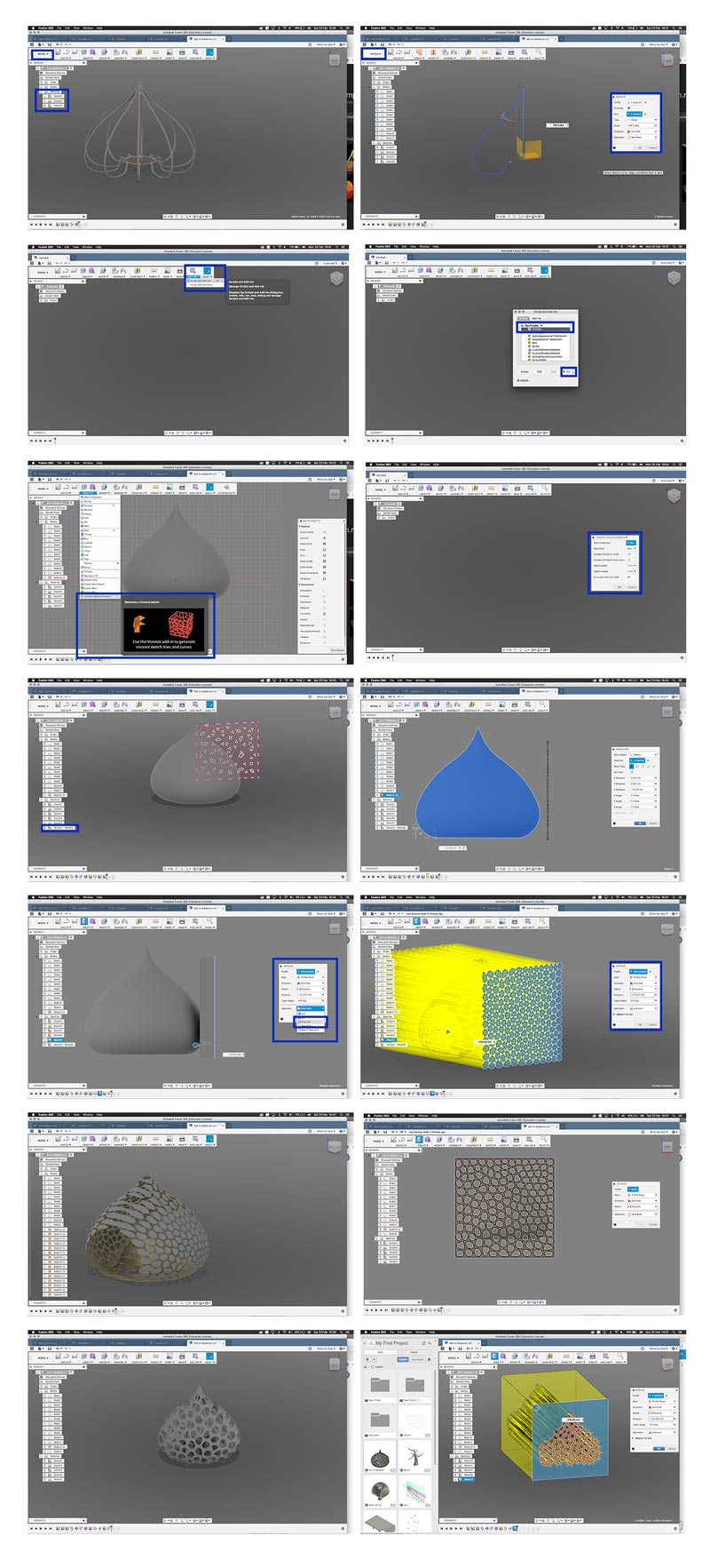 Design 4: Chinese lantern
- First in Model Mode I create the base in a Sketch and I created the profile of the lantern in an different sketch.
- I used the create > sweep function to create the nerves of the leaves.
- With circular pattern I created more nerves around the circle.
- In patch mode I created the revolve, where I used the profile for the nerves as profile for the revolve.
- I thickened the outer shell created by the revolve, this created a new body.
- From here on I followed the steps of the Voronoi generator. It took a while to get a nice patter as the extrude would chafe on the sides. In the end I managed to get it as little chafed as possible.
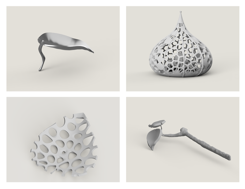 My 3D designs: the leaf, the lantern, the branch and the Voronoi test
3D scan
On Thursday I helped Rutger with scanning himself with the Sense scanner. However I just used the scanner and I didn’t do anything else with it. In stead I tried out different smart phone apps that can be used as 3D-scanner. My goals was to go outside and scan something in the woods. In the end I brought the woods into my home and scanned a branch and I tried to scan a leaf. But the apps I used couldn’t handle the thinness of the leaf. This took me a while to realize.
Trnio
Trnio is an app where you don’t need extra hardware and is available for iPhone. It costs 3,49 Euro but you still have to make an account.
In the end I didn’t really liked this app as it doesn’t give you feedback how to take the pictures and it includes all the surrounding in the picture. This is not useful when I want to use my 3D-scan for editing and 3D-printing. Good thing is that you can export your files without extra costs.
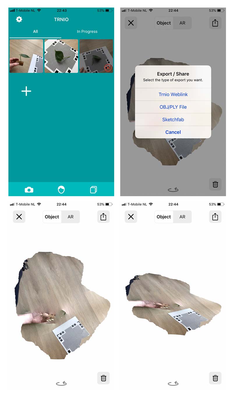 3D scans made with Trnio
Qlone
Qlone is a free to use app, also available for iPhone and usable without any extra hardware. It provides good feedback how to take pictures, you follow the sphere. This is almost a bit additive as you want to fill in all the slots. You have to pay if you want to export your file into an obj- or stl- like format. However once you paid you can export them as many times you want.
Qlone did crash a couple of times without any warnings or reasons why. It turned out that the object I was scanning was too thin for the camera to register. I think this created a glitch in the system which made it crash.
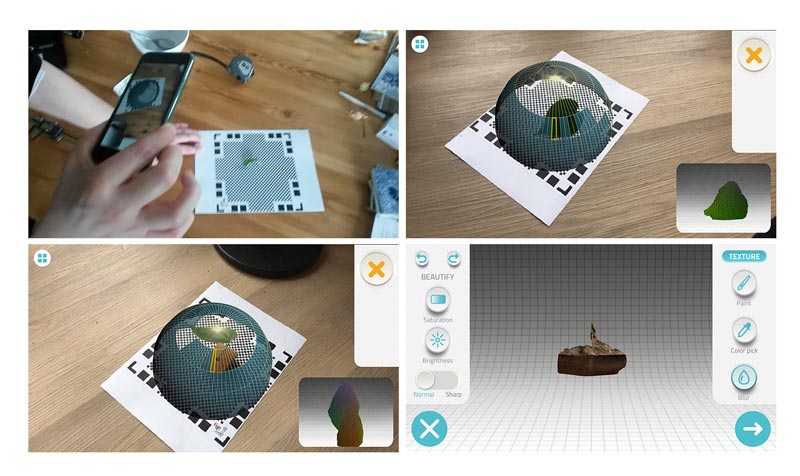
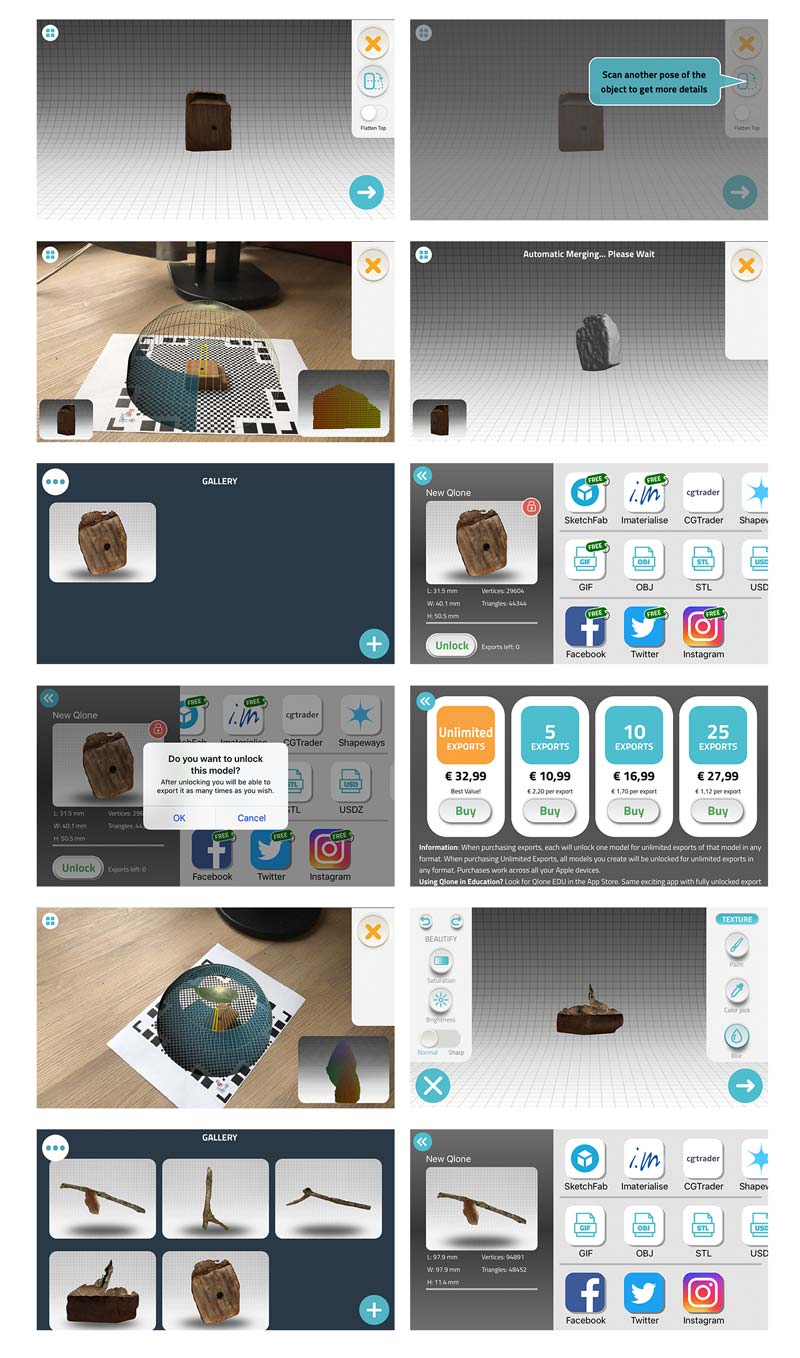 How to scan with Qlone
Once I figured out that the objects to scan shouldn’t be too small or thin, I really liked this app. I paid the 10,99 Euro for 5 exports as I wanted to see if I could use them to make a small design to print. I used the stl-file to combine the real branch with my designed leaves. This was easier than I thought. The scan was also easy to print.
How to convert a mesh file in Fushion 360
To be able to work with the stl-file from Qlone in Fushion 360 I first had to convert the mesh file into a body. I followed the tutorial from Desktop Makes on Youtube:“Modifying a High Poly STL in Fusion 360”
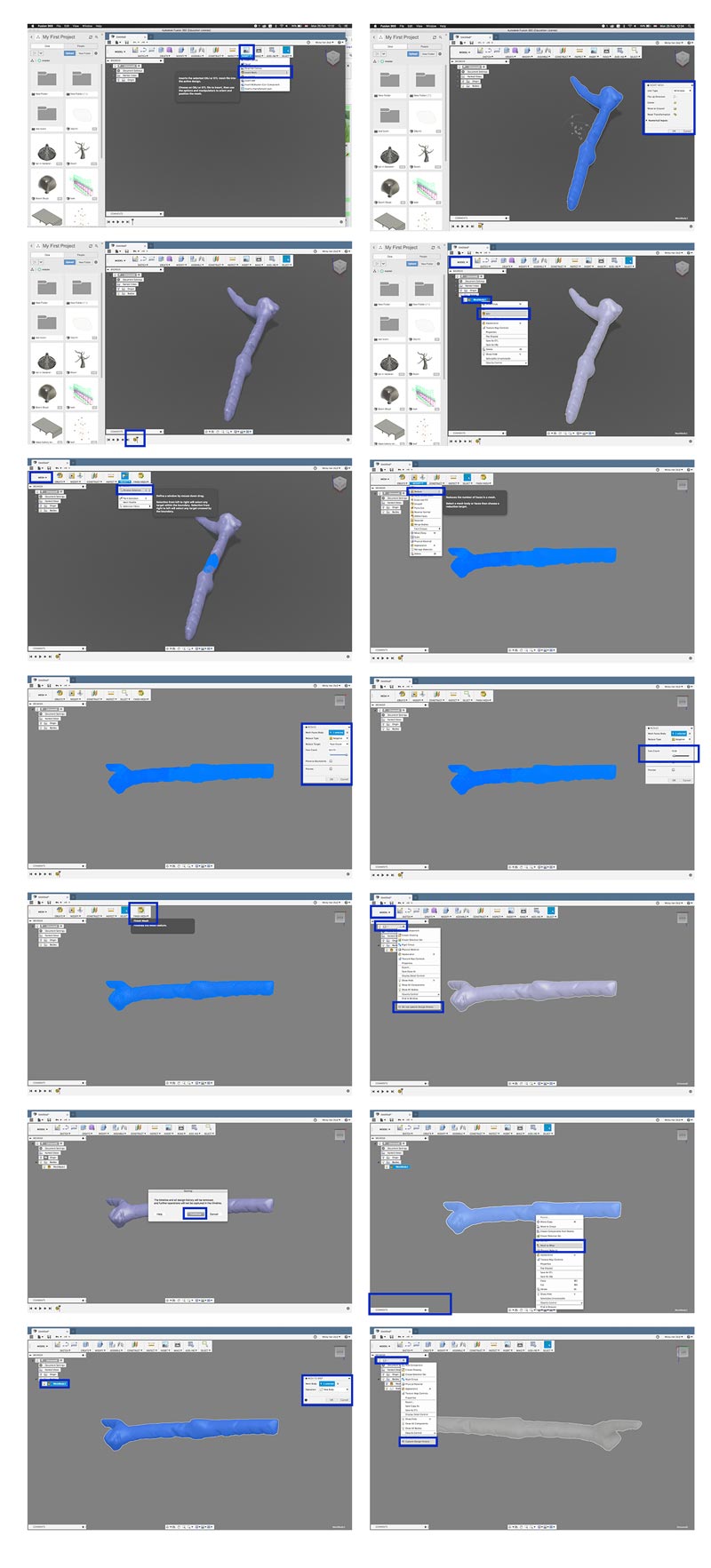 How to convert a Mesh file in Fushion 360
After I converted this file in Fushion I wanted to add my own designed leaf on it. So I imported the file from my previous design into the document I just edited with the Mesh file. I move the leave around in such a way it was at the end of the branch and I copied it one time so it wouldn’t be alone on the branch.
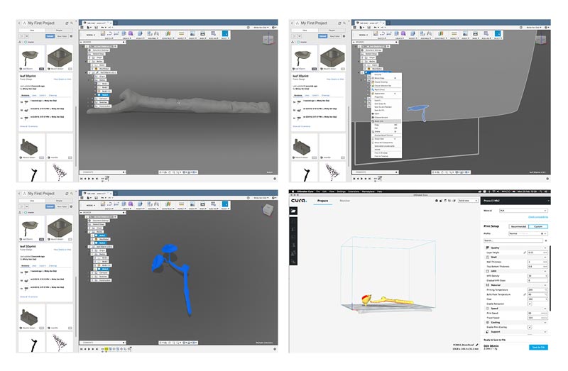 Design 5: scanned branch with leaf design
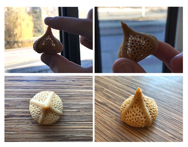
I liked the design and my next test was to figure out if this would work in the 3D-printer. I used the Ultimaker 2+ at the Makerslab. First I wanted to try how it would look with filament with a wood look. However this material is less subtle. After my first print I noticed my design is really fragile, especially the leaves and the twigs. The branch looked really nice and realistic with the wood filament.
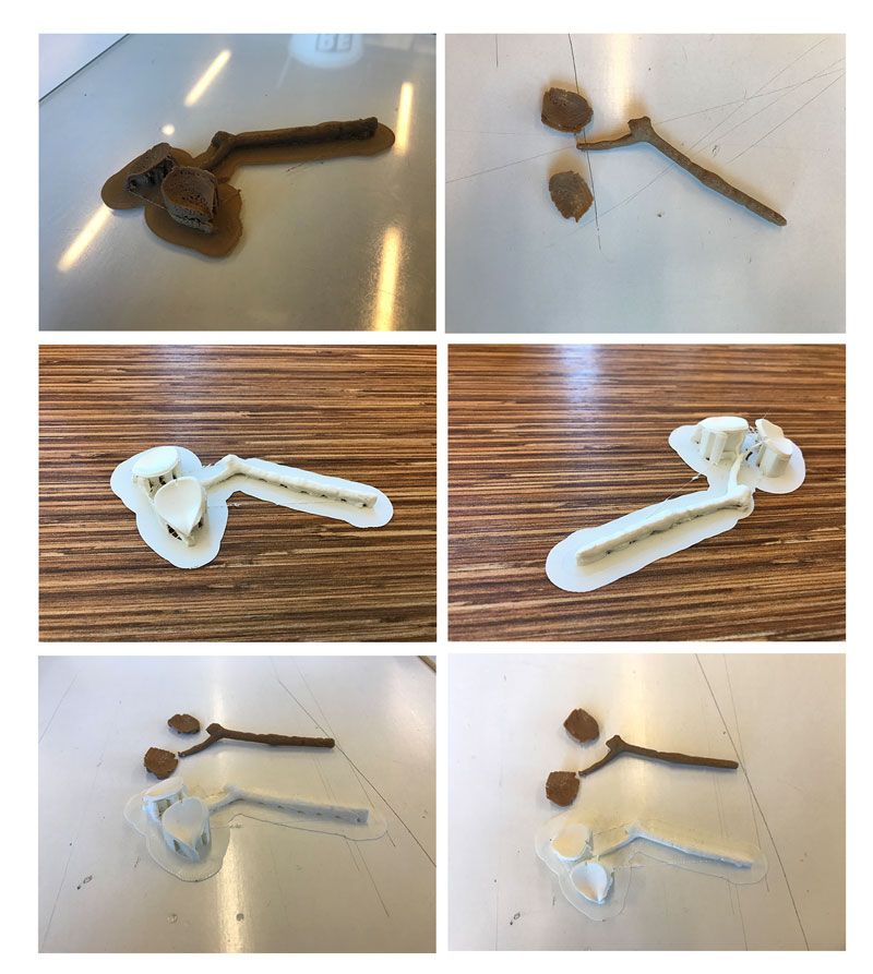 3D print Design 5
To make sure the leaves wouldn’t break I added some thickness to them. I couldn’t figure out how I could add thickness to the twigs. I made these in the skulpt mode in Fushion 360 and I’m still not sure how to edit this. I restarted the print again with a bit thicker leaves and with PLA white filament. I really like the end result altough the twigs are still really fragile.
3D print
This week I went to the Makerslab of my university because I needed PVA or other support material that’s able to dissolve. I’m familiar with the Ultimaker 3 and how to print with PVA as support material. At the Makerslab we also have an uPrint, this is a more high end 3D printer. I used both the uPrint and the Ultimaker 3 for my Chinese lantern design.
I wanted to see if I could print my 3D scanned branch with leaves with the Prusa at the Waag. However the printer was fully booked this week. So in the end I also used the Ultimaker 2+ at the Makerslab for my branches. The results for this print can be found above.
 End Result 3D prints
uPrint
uPrint doesn’t work with Cura but with Dimension. So first I had to open the stl-file in Dimension and prepare the file for the printer. The images below show the steps I took. I set the properties of the print really hight because the design was so fragile. In the end I decided not the scale the file too much because I wanted to see how my design, as I made it in Fushion 360, would look in ‘real’ size.
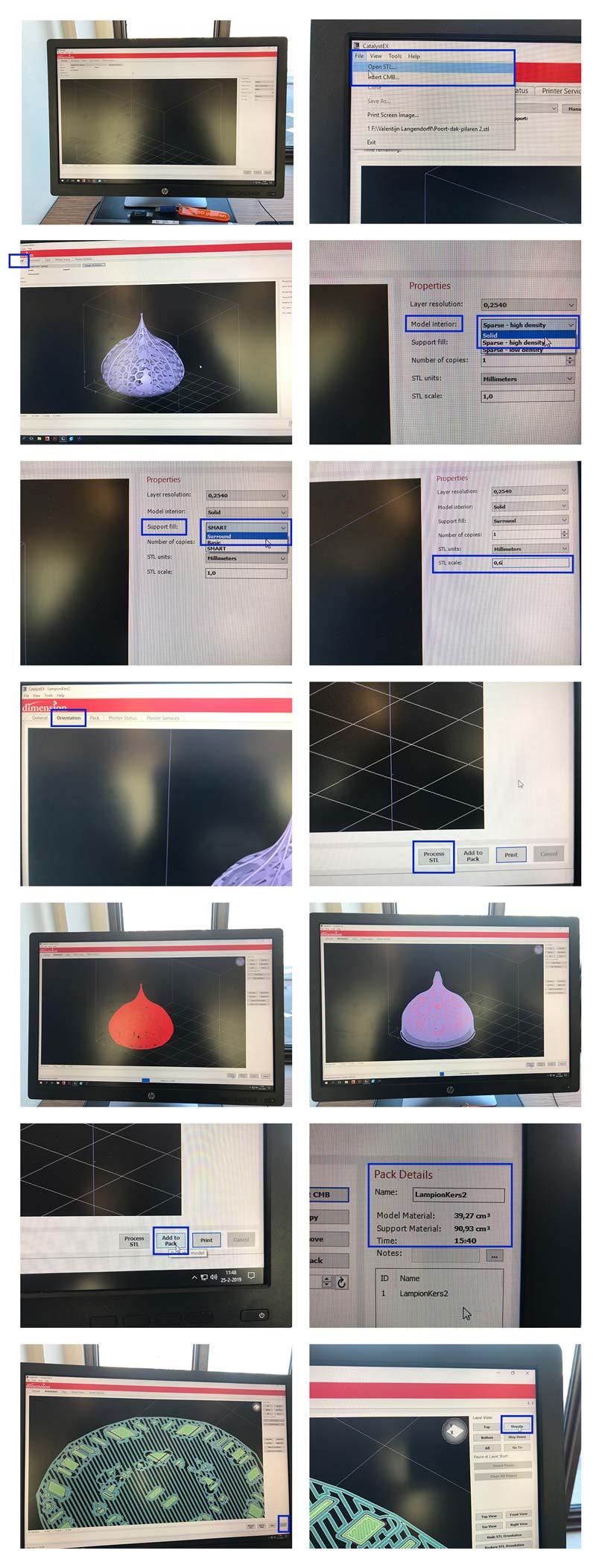 Preparing the file for the uPrint
After setting up and preparing the file in Dimension, you just follow the steps on the printer. This is really easy, I think the uPrint is one of the easiest printers to follow.
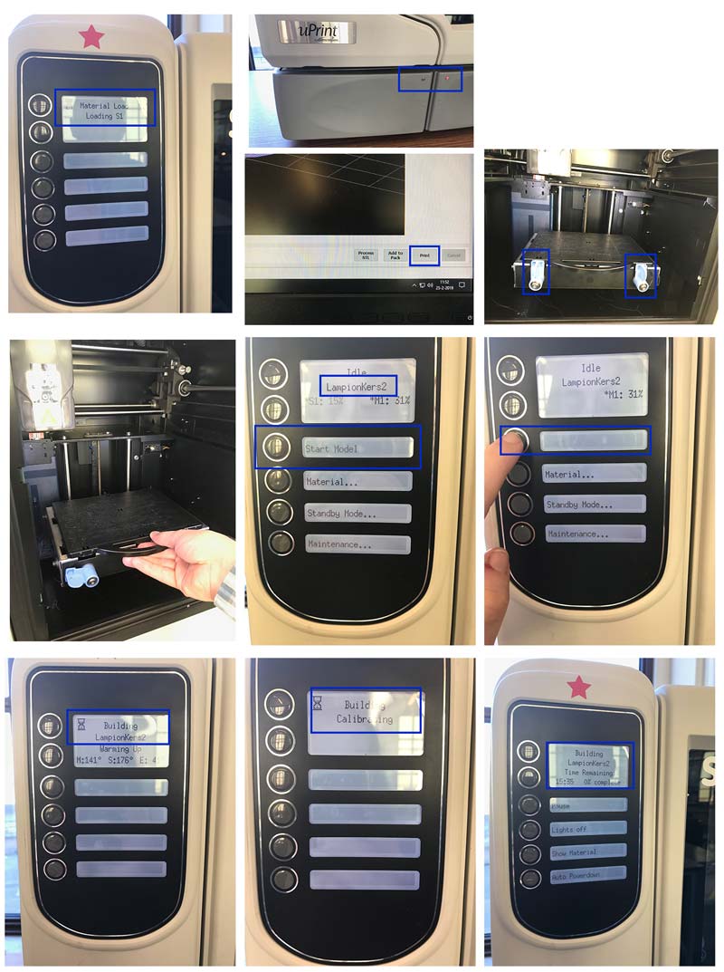 Setting up the uPrint to print my design
The file took 15 hours to print, which is a really long time and therefore it doesn’t fit the requirements of this weeks assignment. However I kept it this way because I wanted to see how my design would turn out in the scale I designed it in. Because when I scaled it, it became too fragile to print. This way I hope to learn something about scale and 3D design.
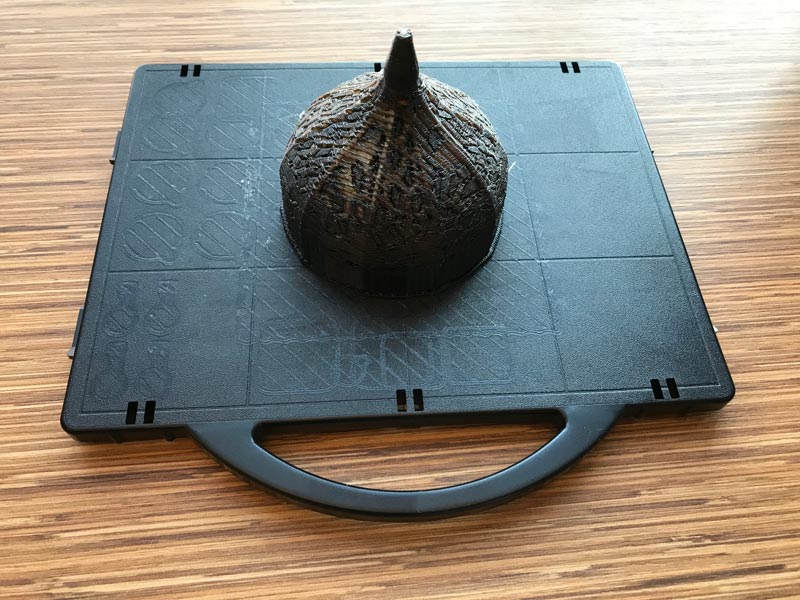 Finished Chinese Lantern print from the uPrint with support around it
Removing the support with the Wave Wash
The next day I place it in the “wave wash support cleaning system”, it takes another 12 hours to wash away the support of the 3D print.
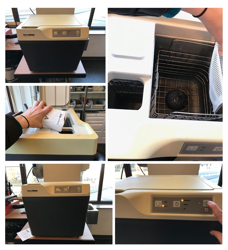 Setting up the Wave Wash
When I came back the next day to pick it up the machine had an error. First I forgot to open the tap. But when we tried again it didn’t want to heat up. The Wave Wash gives problems more often so probably the machine needs maintenance or is fully broken. In the end it worked the next day and we put the print in twice to make sure every support material was fully washed away.
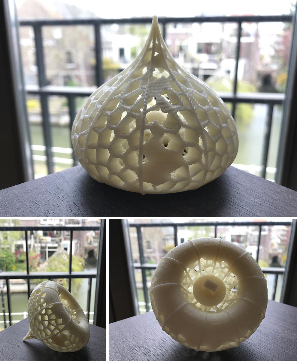 Finished Chinese Lantern print from the uPrint
Ultimaker 3
I used the Ultimaker 3 for the smaller version of my Chinese Lantern. Before I could print this one I had to redesign some parts of the lantern to make sure it was thick enough to print. I added thickness to the outer shell, in addition I thickened the nerves and reduced the amount of nerves on the lantern.
In one nozzle I used PVA and the other PLA. In Cura you can define from which nozzle you want support. So I started the print.
 Setting up the Ultimaker 3
When the print is finished you can see the PVA support, the see-through material, all around the 3D object. To wash this away the only thing you need to do is place it in water. Best is to move the water around a bit, but when you have time you can also leave it there for a night.
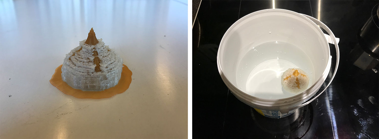 My Chinese Lantern print with PVA support
The PVA dissolved after I left the print in water for a night and a day. In the end result you can see the small sphere within the lantern shape.
 End result Chinese Lantern
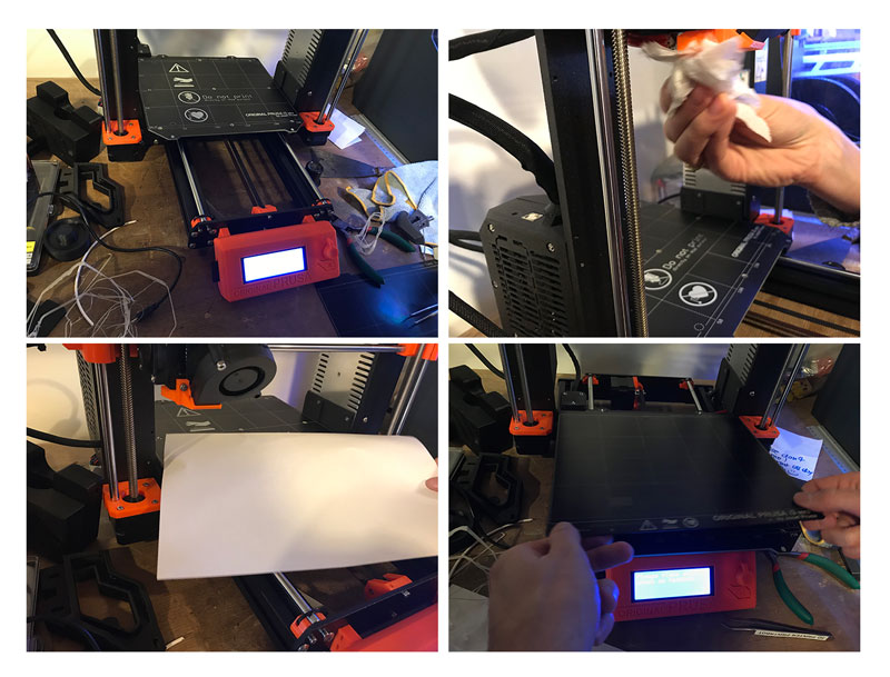
What we did wrong – and how we solved it
While we were working on the test for the Prusa we encountered a lot of problems. Somehow we didn’t manage to get the right first layer calibration. All the test we did the material would stuck. What we thought was wrong:
- First we thought it was our material. We changed the filament back to the gray one as we knew this worked. However with the first layer calibration it also didn’t work with the gray filament
- So we thought it must be our experiment with the layer height so we changed this back to the recommended option in Cura to the 1.15 mm. However again this didn’t help with the first layer calibration.
- Next we thought we should do a xyz calibration as the printer is new and this might have changed while we switched material. However when we followed all the steps again now right result with the first layer calibration.
- We tried different first layer calibrations to see what would work if we varied in the z-axis. This didn’t make a big difference we still had the same problem.
- We then thought the nozzle was clogged with filament, so we cleaned the nozzle. But again this didn’t work.
- After a while we noticed that the problem was not that the bed wasn’t straight but that the material would pull off from the bed. This would mean there’s something wrong with the adhesion.
- We double checked the bed. We cleaned it with alcohol so all the time we thought this was not the problem. However somehow the bed felt really oily. Which is weird because that’s not what you aspect from alcohol.
- We flipped the bed to test if maybe this would make a difference…and it did!!!
- In the end the problem was the material we used to clean the bed, it turned out this wasn’t alcohol but something else (we still don’t know what) even though the bottle said it was alcohol.
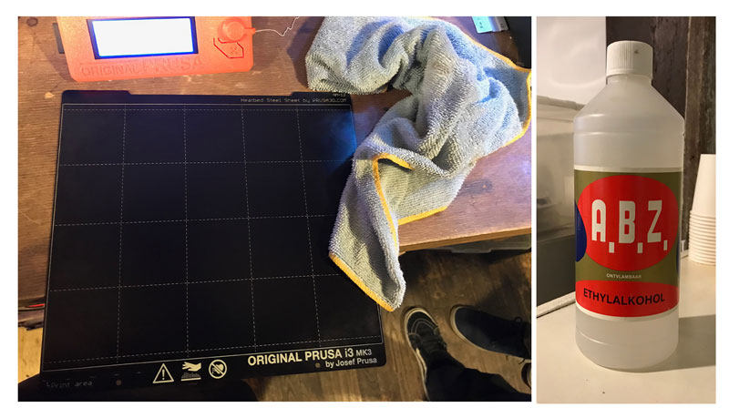 Always double check what’s a bottle
What I did wrong – and how I solved it
While designing in Fushion 360 I moved back and forth quite a lot. In the end my design file of the Chinese Lantern with the Voronoi pattern became really slow to edit. I think this must be the processing power of my computer or the complexity of my file.
Scanned something too small
My Qlone app kept crashing when I was scanning the leaf I wanted to scan. When I tested with a solid wooded block it did work so I couldn’t figure what was wrong. First I thought it must be storage. Because I got it working with the wooden block I added the leaf to the block and scanned both of them together. This time Qlone didn’t crash and it showed that it didn’t register the leaf at all. Which made me realize that the leaf itself was too thin for the Qlone app to scan.
 Too thin to scan
My final design was too fragile
While designing in Fushion 360 I didn’t pay attention to the size at all. Especially in skulpt mode, I somehow forgot to think about the size, thickness and proportion of my design. Which I though was quite funny because I often see this with students who want to 3D print a file and are confused when they place it in Cura to slice.
The Wave Wash didn’t work
When I came back on Wednesday to pick up my 3D print, it turned out the wave wash didn’t work. First of all I forgot to open the tap for water. This gave an error. However when Cees arrived in the morning and restarted the program it still didn’t work. The machine is a bit old. It wouldn’t heat up. We restarted the machine again and hopefully this time it will work. For the second time it’s seems that the thermostat in the Wave Wash isn’t working anymore. The Makerslab already order a new machine. So I have to wait for that one to arrive to see the end result.
What I learned
This week I learned a lot especially if it comes to working with Fushion 360.
Always check the bed plate for adhesion
I now know how to calibrate the Prusa very well because I didn’t check the bed. So my lesson learned this week is for sure know what’s stored in the cupboard. Double check the adhesion of your plate before starting an endless calibration session.
Size matters
Both with 3D scanning and printing size matters and I learned that I really easily get lost in the digital representation of a 3D shape or object and completely forget to think about sizes.
Remove the support when it’s hot
For my second leaf I waited to remove the support because I thought the design was to fragile. However once the support is dried out and not warm anymore its more difficult to remove.
The difference between additive and subtractive design
I thought a lot about the difference between additive and subtractive design and my design would fit the requirement “that could not be made subtractively”. To get an better understanding of this difference I thought about techniques I better understand. In Dutch the technique on first picture is called “boetseren”on the second, the one on the right, it’s called “beeldhouwen”. The first picture is an additive design process because you add material to create a 3D shape and the second picture is a subtractive design process because you remove material to create the shape, object or sculpture. It really helped me to keep this image in mind while designing this weeks assignment.
 Additive vs subtractive design
What made me proud!
My 3D designing skills in Fushion 360 improved a lot. If I compare my first file and the long time line it has with my last design file, I can see that at least I got more used to how to work with the time line in Fushion 360. My aim for this week was to practice with Fushion 360 as I already had some experience with the 3D printers while I had none with designing. I made a lot of different versions and designs. I’m especially proud of the leaf I made in sculpt mode.
Credits and references
This week Annemieke helped me with the idea of the Chinese Lantern and how to install the Voronoi script. I went to the Makerslab where Cees reminded and explained me how to work with the uPrint.
Research articles
- Lantada, A. D., Romero, A. de B., Isasi, Á. S., & Garrido, D. (2017). Design and Performance Assessment of Innovative Eco-Efficient Support Structures for Additive Manufacturing by Photopolymerization: Eco-Efficient Supports for Additive Manufacturing. Journal of Industrial Ecology, 00(0), 1–12. http://dx.doi.org/10.1111/jiec.12660