The week with "problem of plenty"
1. Laser and Vinyl cutter both are fast and would would easily make a designer think more and do more in a week's span. Hence, it gives lot of room for experimentation.
2. Miscalibration is truely a nightmare especially when it happens to a laser-cutting machine. A bad calibration results in lot of charring and ends up .
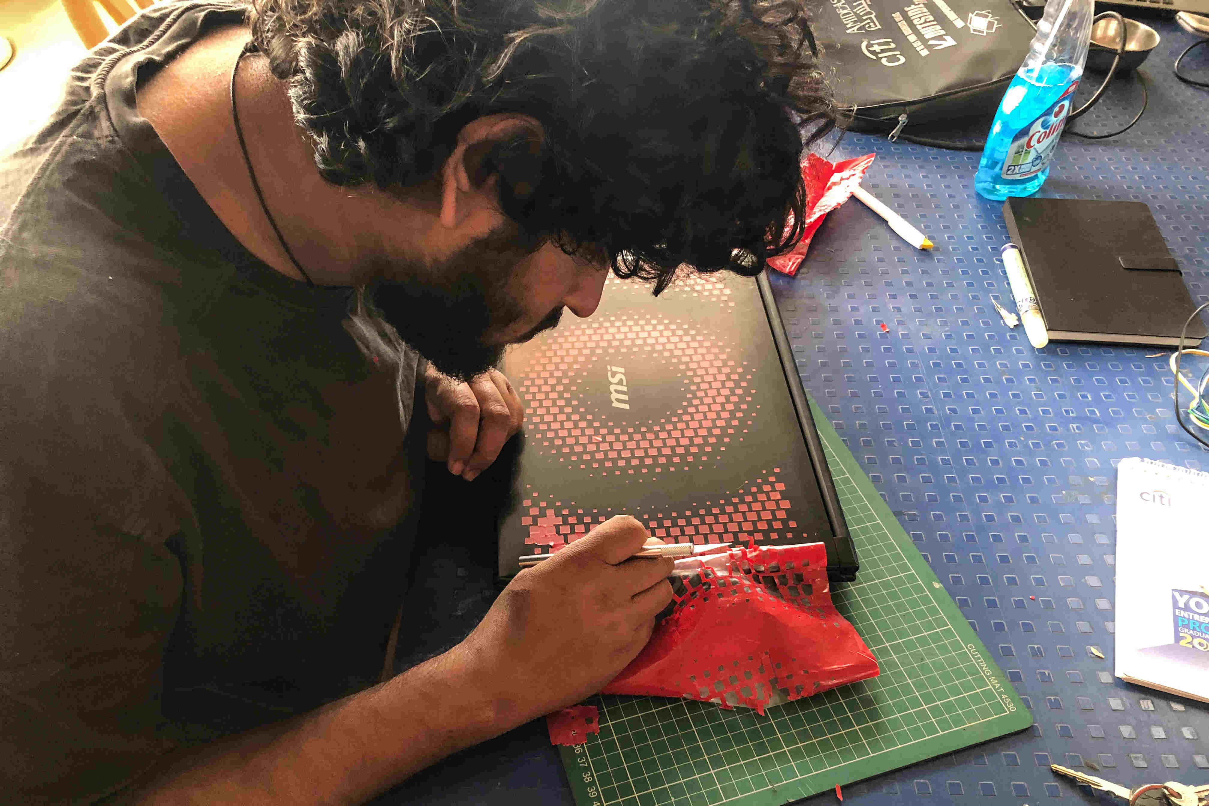
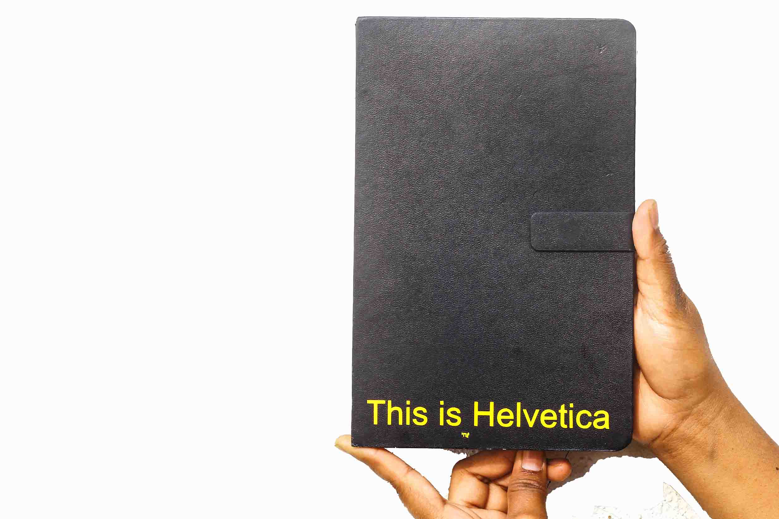
3. The neglected one, "a vinyl cutter" would leave you amazed if you get the design right. PS: you can put in anything else too instead of a vinyl sheet, the machine isn't intelligent enough to detect it.
Laser Cutting
Brief Overview
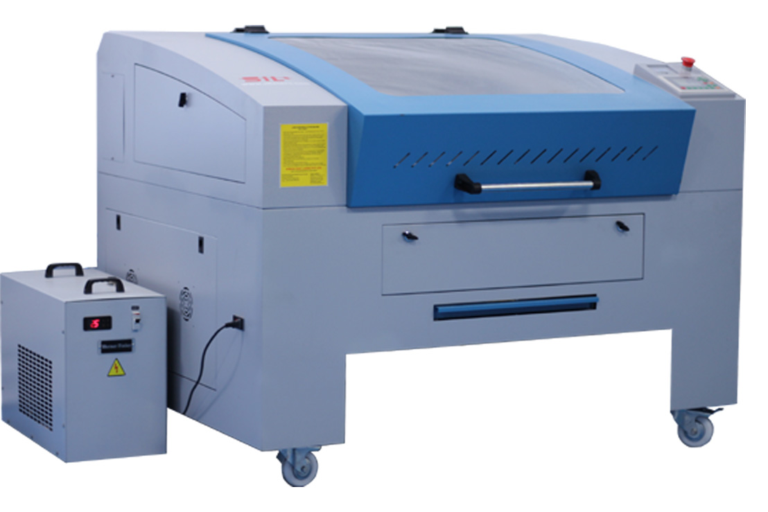
I had some experience with Laser cutting before, while designing my 3D Printer at Fab Lab CEPT. At Vigyan Ashram, Pune we are using SIL Laser(CO2 las in a glass tube). On one hand it is a very important tool in the lab but a special importance has to be placed on safety above everything else. A laser cutter has its own limitations, while it can cut smoothly through MDF, Acrylic and Cardboard it shouldn't be used for materials such as metal as it can bounce the laser back. One of the important instructions we were given was to use laser cutter only in the presence of Lab Instructors. For this week, I used Laser Cutter on three different occasions, firstly to calculate the kerf for acrylic, secondly to cut a living hinge and lastly a waffle structure for press fit construction.
Things to remember
a. Check whether the material to be cut is straight or not, from my personal experience, MDF and acrylic sheets are usually bent. This can result in varying level of cutting and inaccurate results.
b. Check how many files the laser cutter can store in its memory and keep removing the ones that are not required.
c. Do not leave the laser cutter un-attended while in use.
d. Wait for a minute after the laser cutting is finished. The exhaust takes a while to remove all the fumes.
Kerf Calculation for Acrylic(Group Assignment)
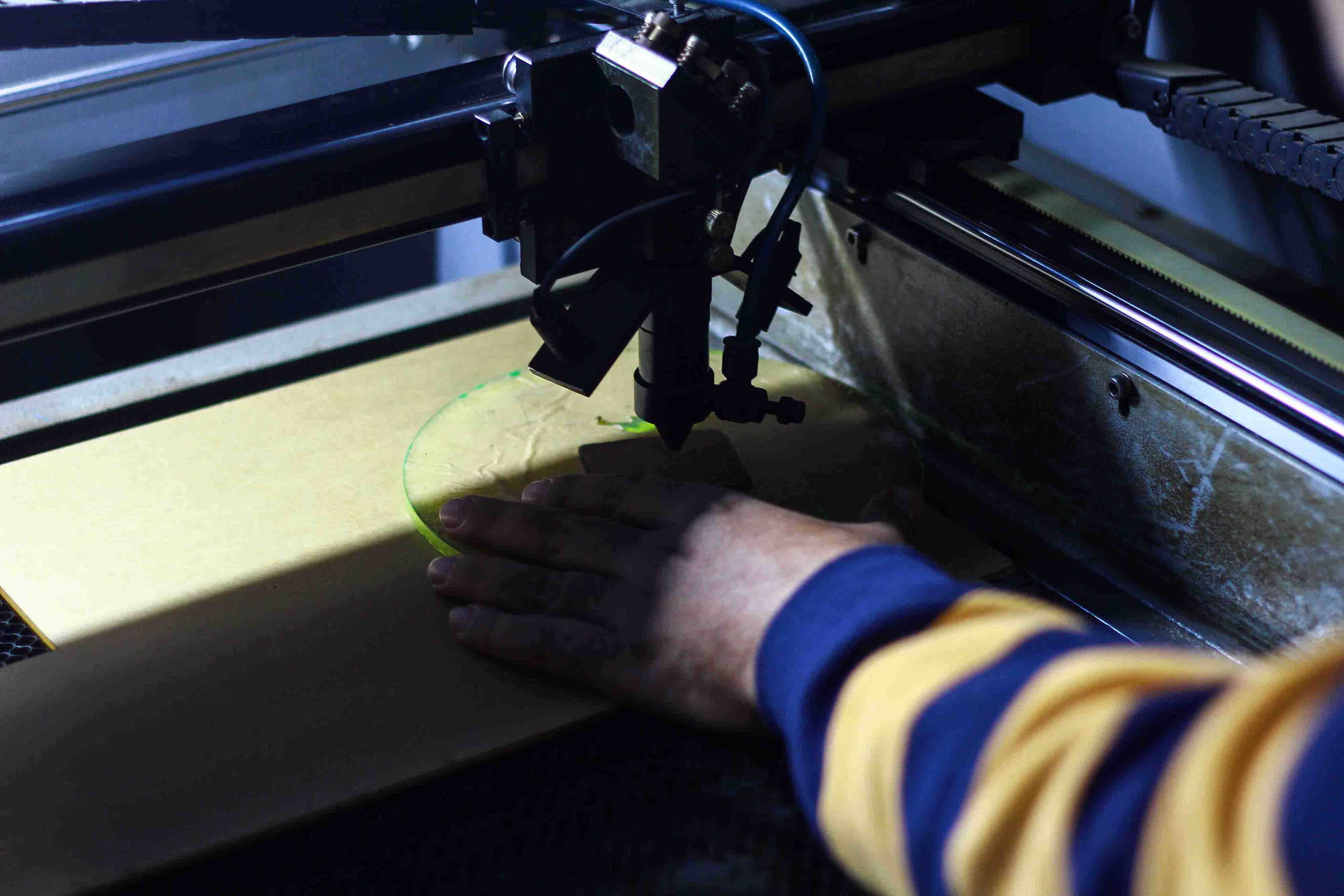
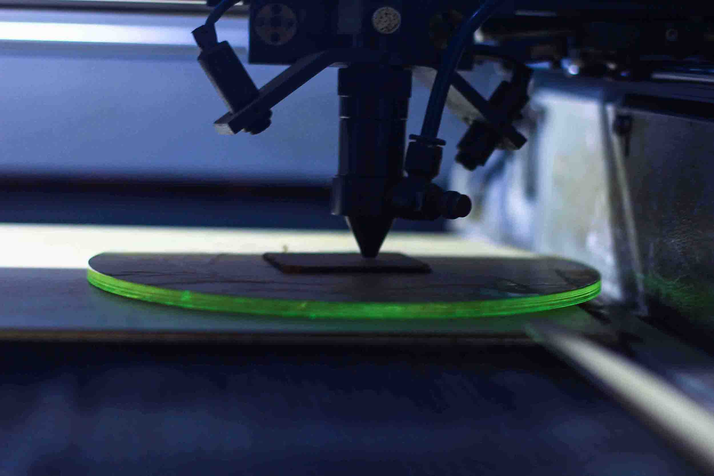
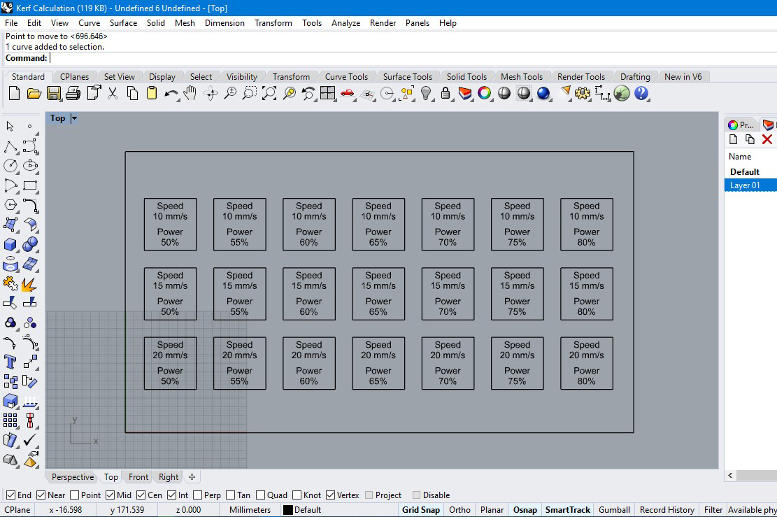
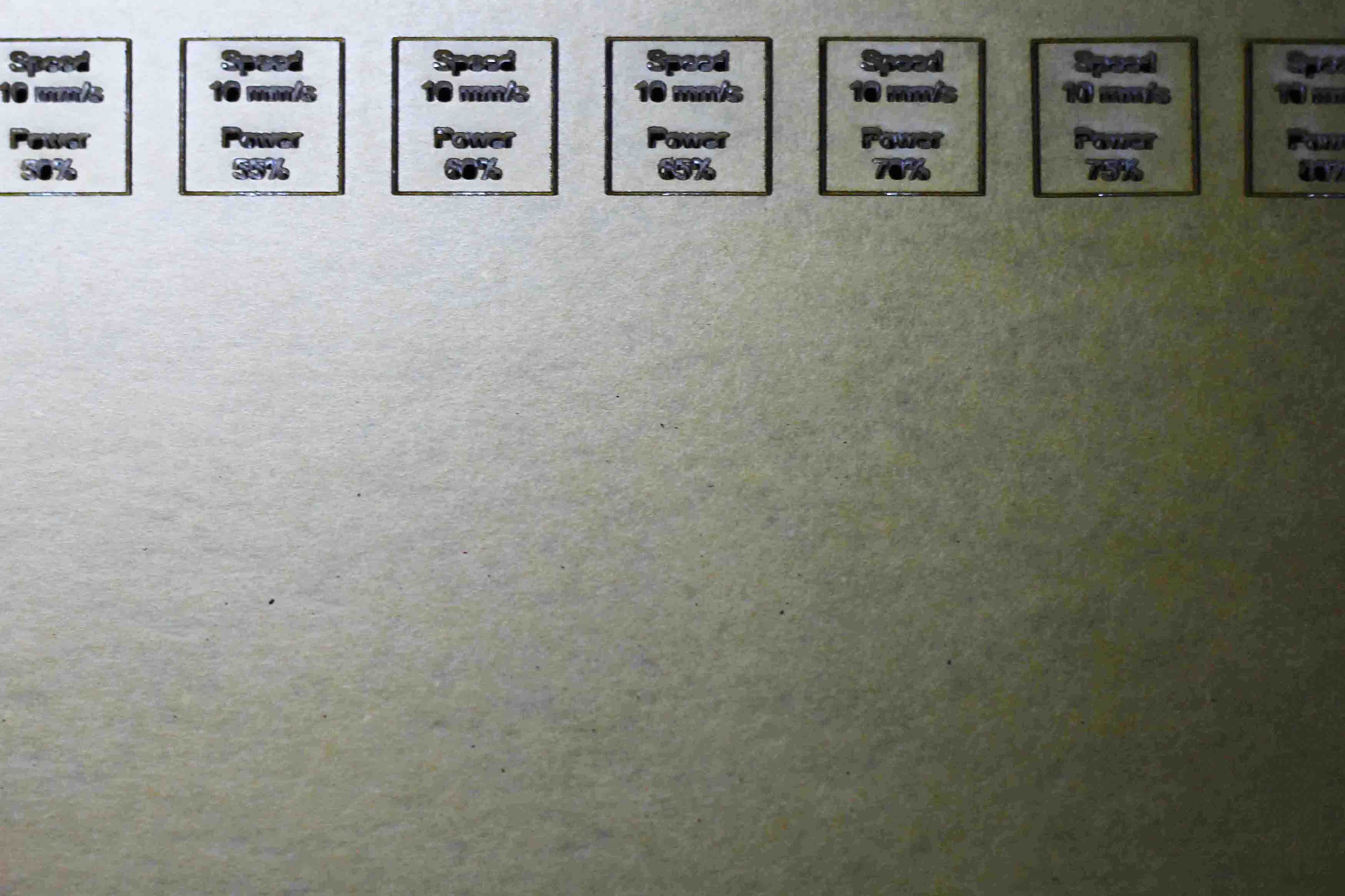
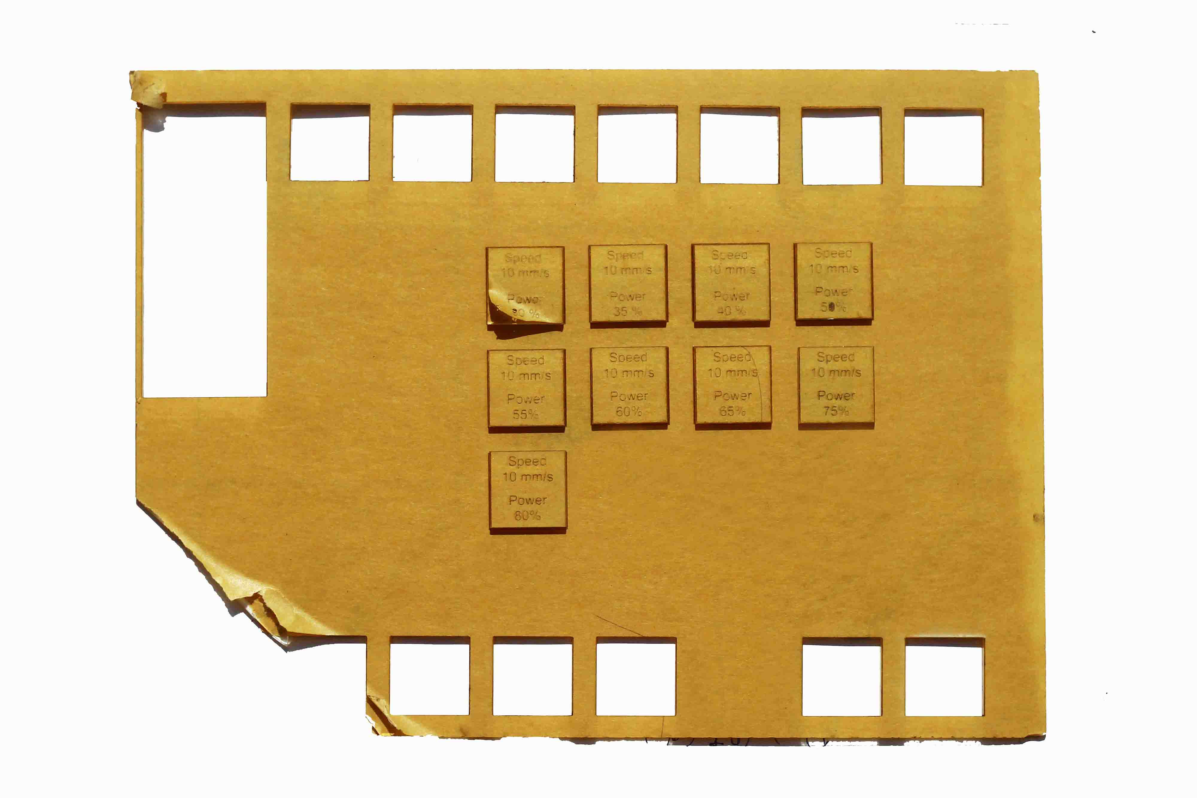
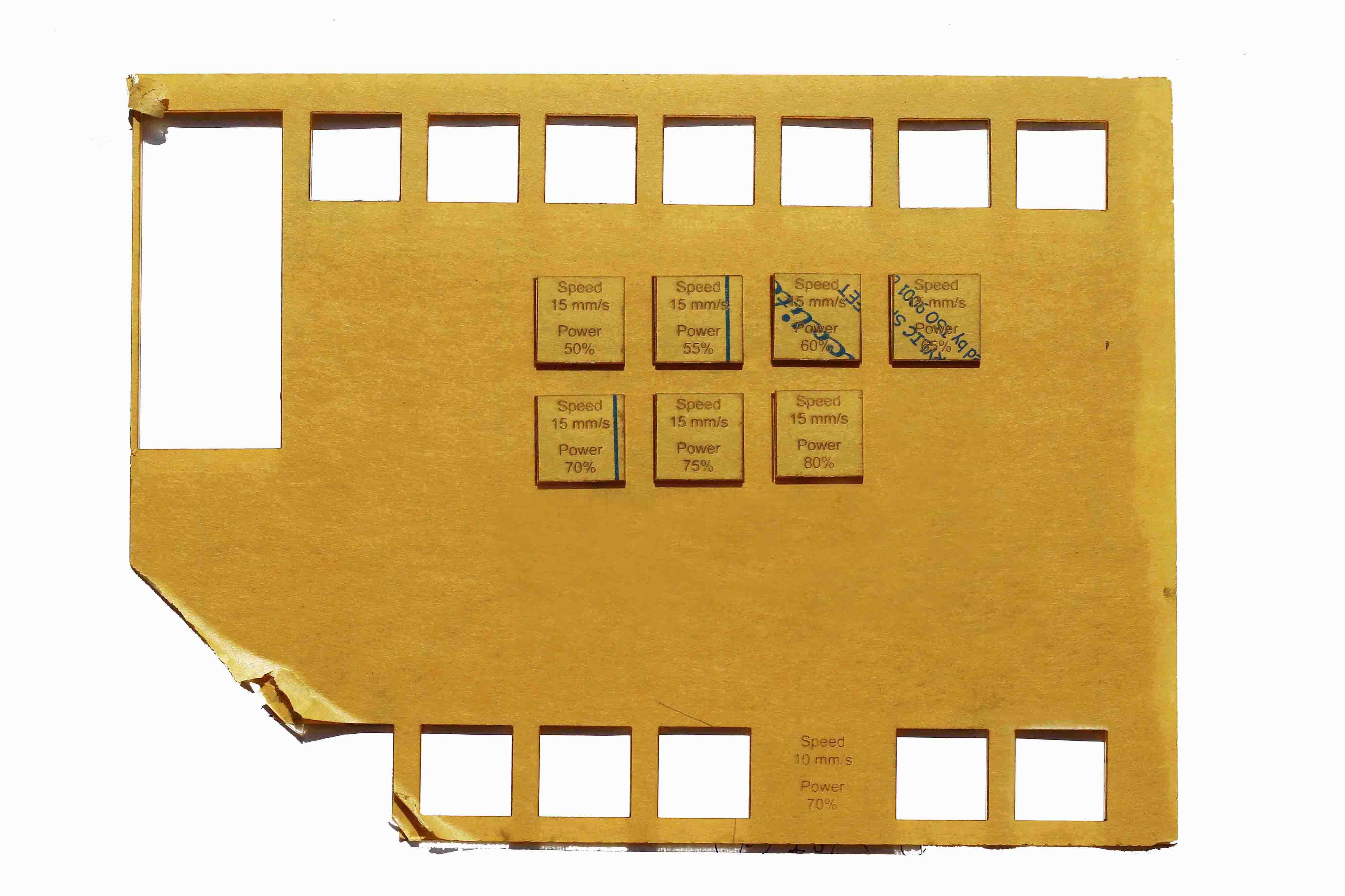
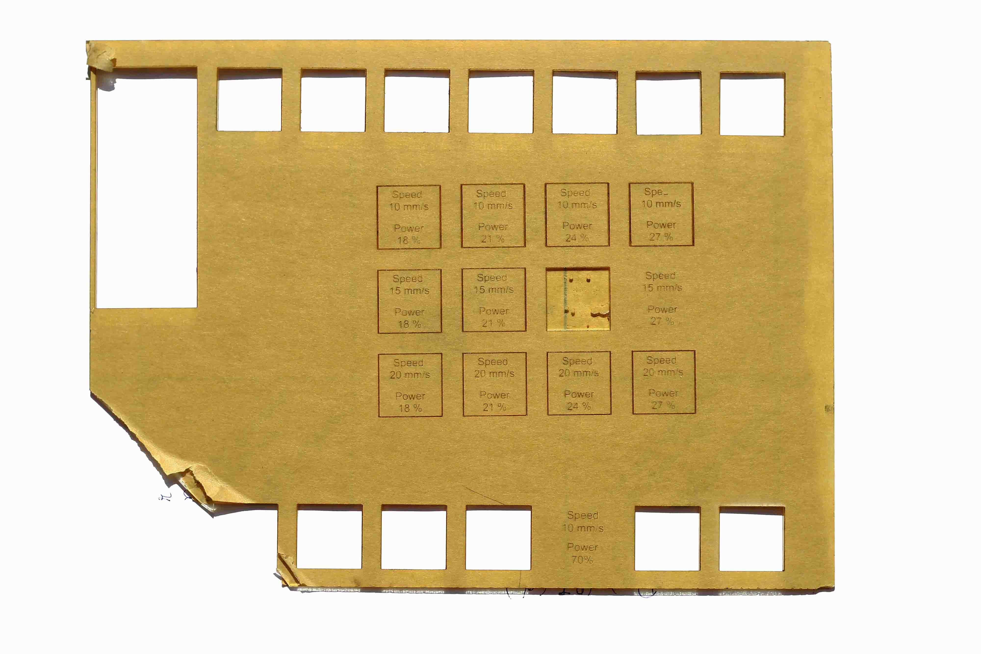
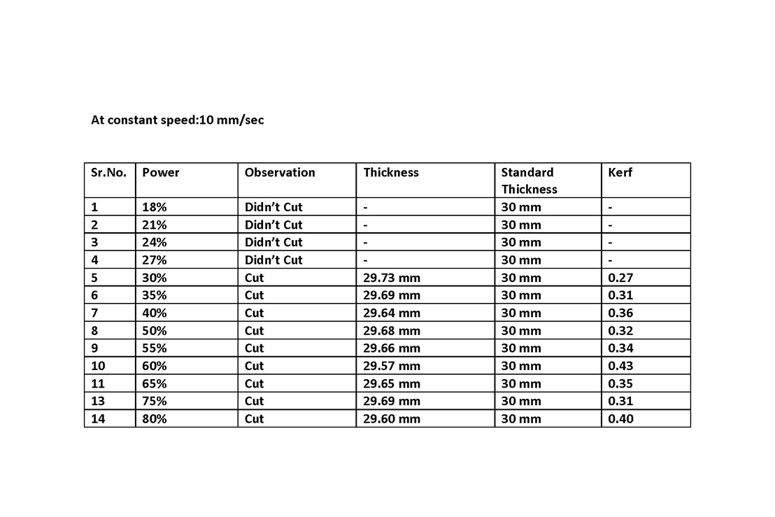
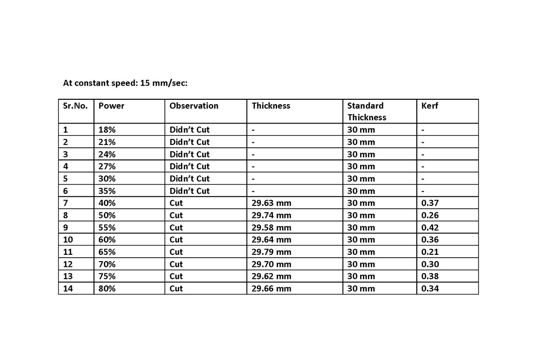
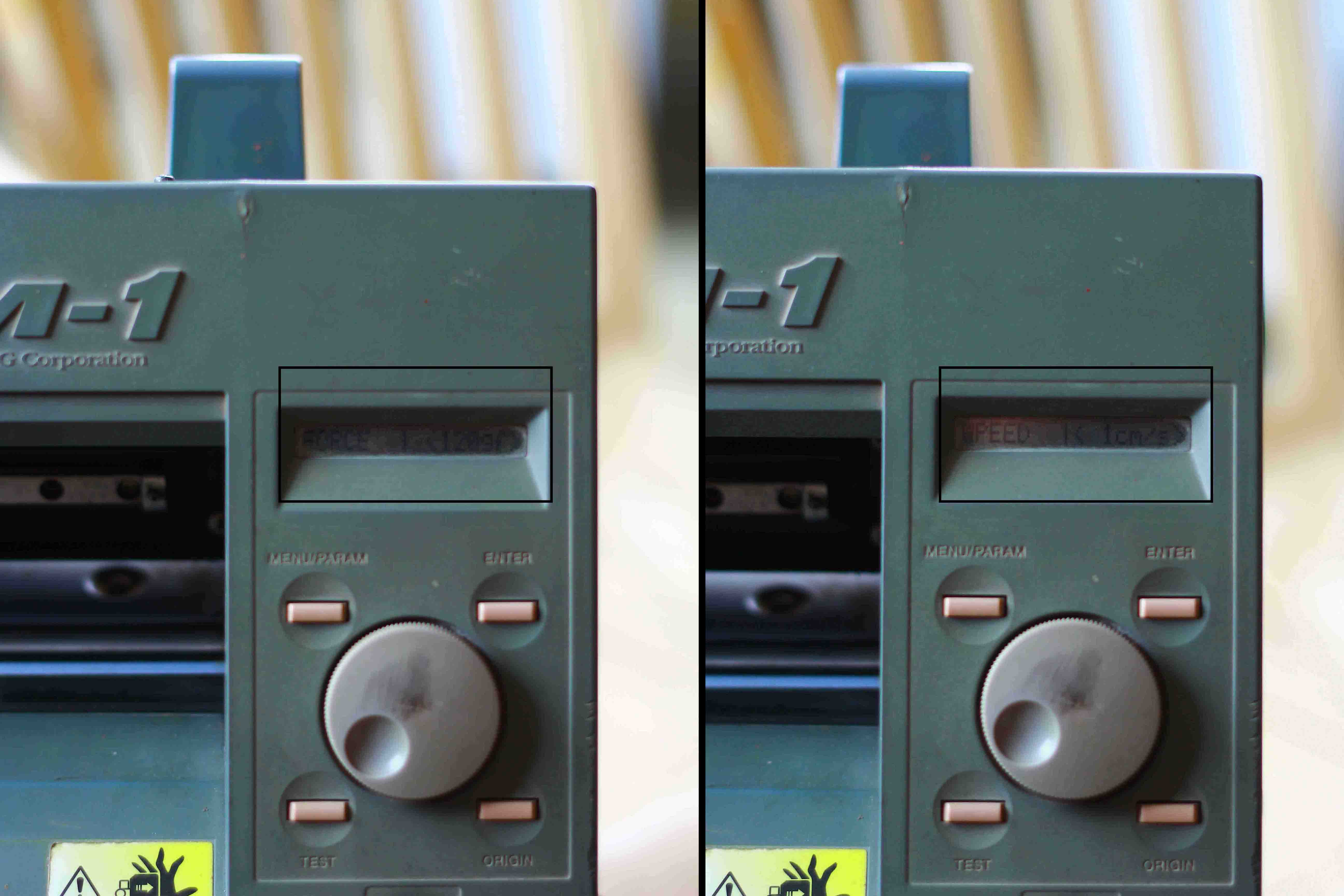
I partnered with Tushar Kukreja to explore the kerf of 3 mm acrylic using SIL Laser at various settings. One of the main aims of this exercise was to calculate the amount of material lost during the laser cutting. We took a series of steps to calculate the kerf (defined as the width of material that is removed by a cutting process). We took the following steps to calculate kerf. It is described as follows:
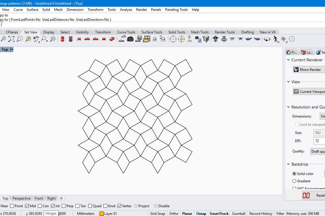
a. Designed on Rhinoceros 3D: Made squares of fixed size 30 mm x 30 mm with corresponding speed and power labled on them.
b. Commands to machine by RDWorks: Made different layers for scanning and cutting. Mentioned command for power and speed for every square.
c. Laser Cutter: Standardized the distance between the acrylic sheet and laser tip(z axis distance), origin and frame to cut the pieces.
d. Measured Kerf: The length of the sides of the squares ws measured using Vernier scale.
Conclusion
a. The minimum Kerf keeping speed at 10mm/sec is at 30% power and at 15mm/sec is at 65% power for acrylic.Thus, characterizing the laser cutter.
b. Applying this data will will save power and cut acrylic precisely.
c. Minimum Kerf data will be useful for press-fit designs, adjusting Kerf values in slot thickness.
Living Hinge(Parametric Hinge)
After looking at various examples of living hinge or lattice hinge. I wanted to explore and create my own patterns for pre defined bending. Before that, I took a predefined pattern created by Kofactor Lab and laser cut it to see how it bends. I took a power setting of 60W and 10 mm/s. I personally liked how density, length of cuts can have a major effect on the torsion of the material. The predefined custom cut pattern created the effect of a rubber sheet and was bending in both sides behaving as singly curved and doubly curved surface.
Download the file here
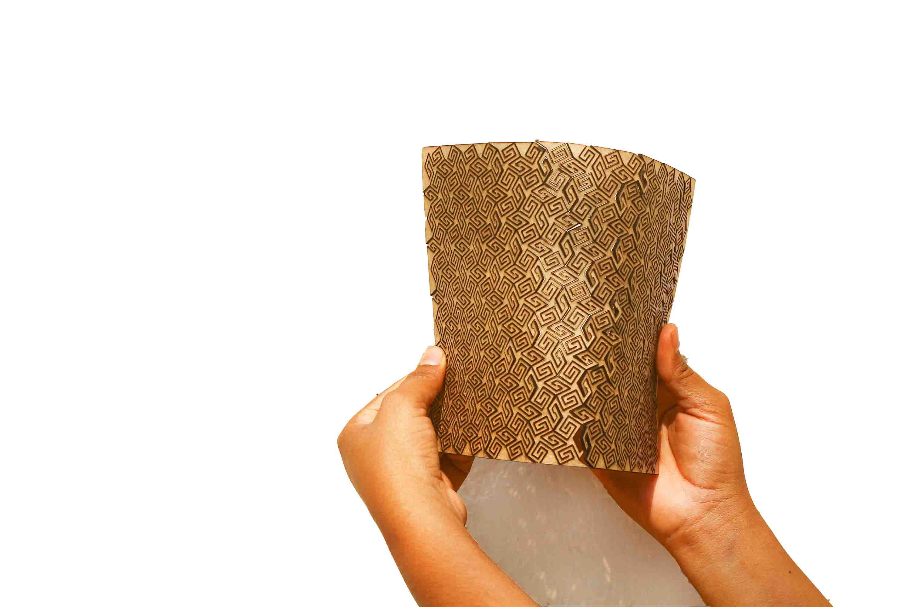
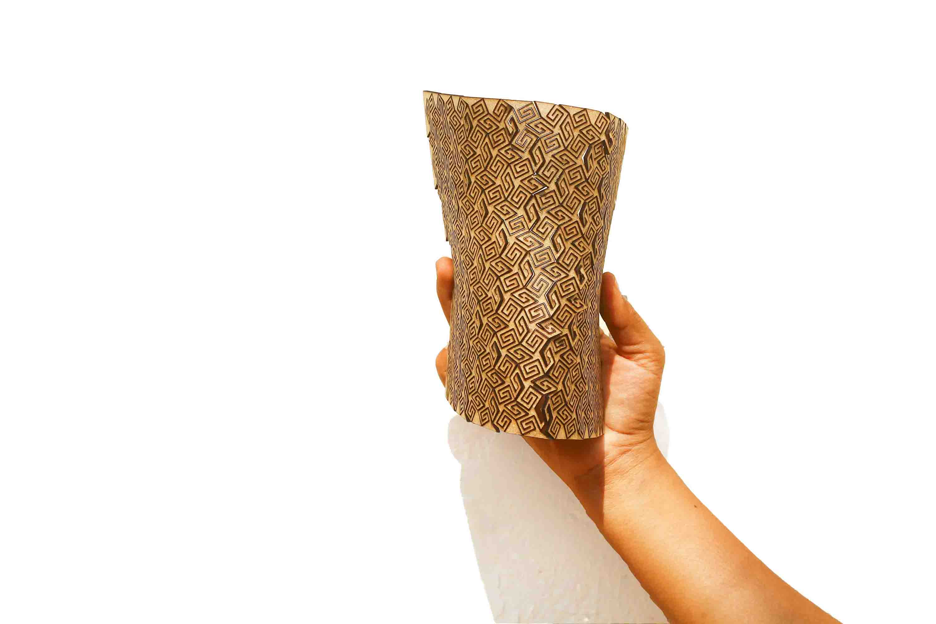
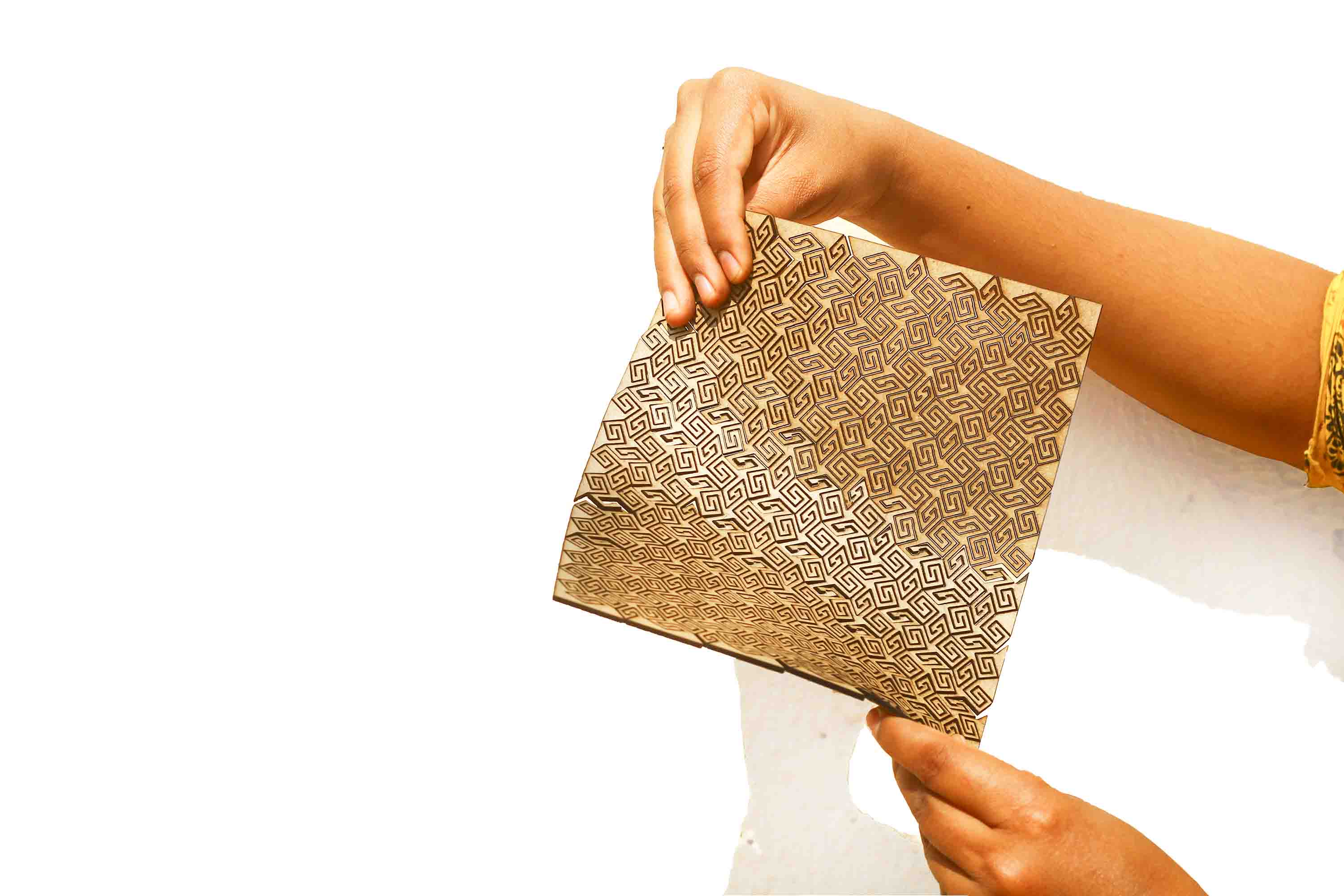
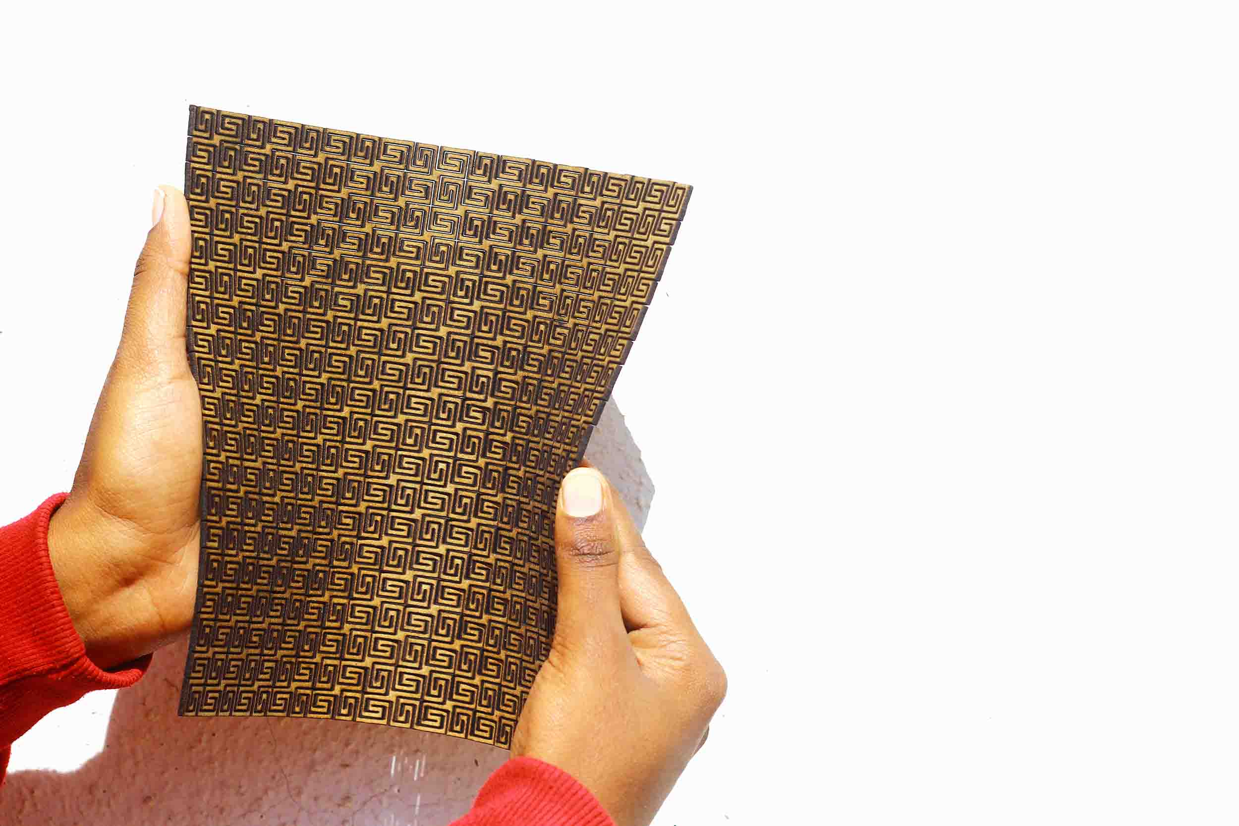
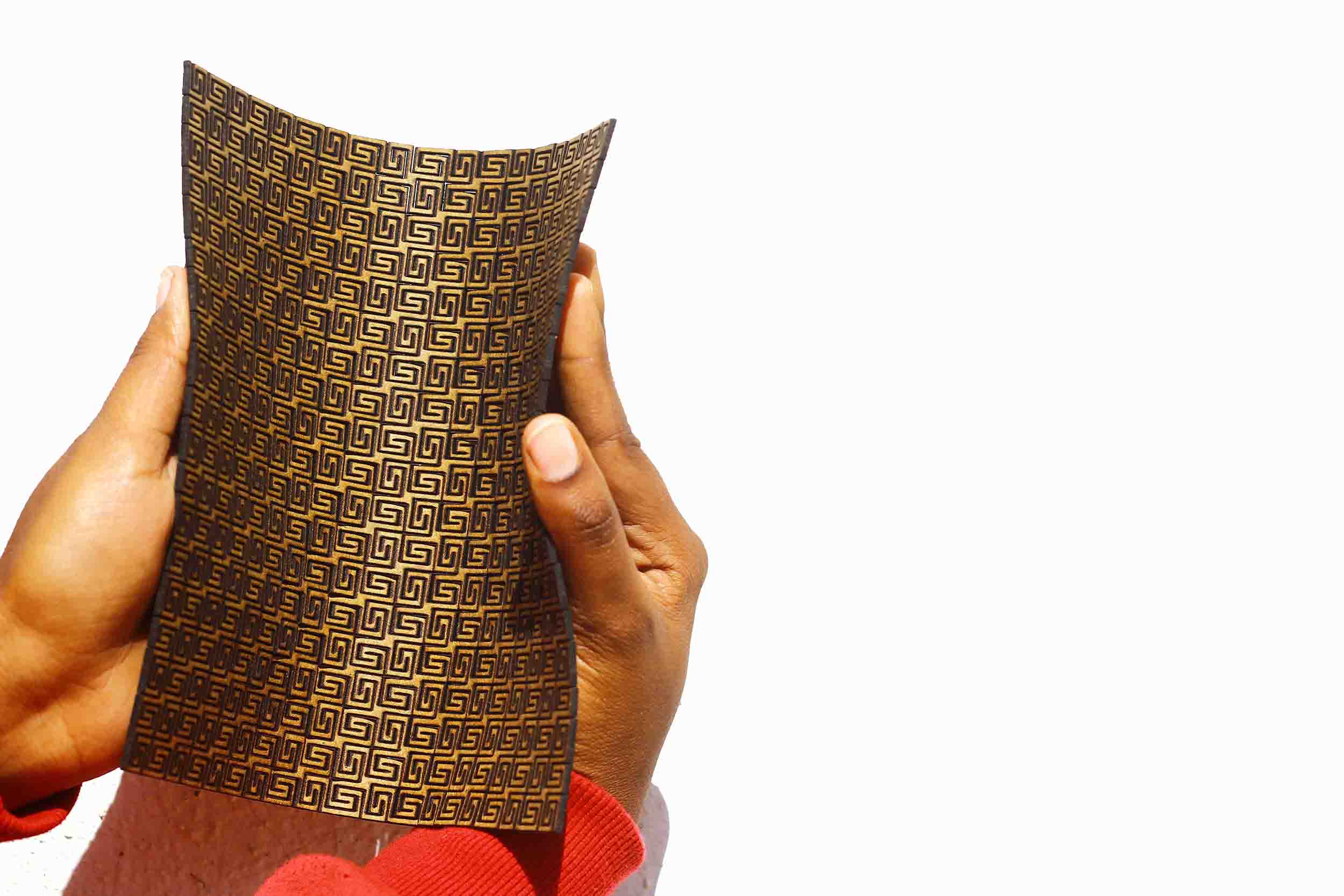
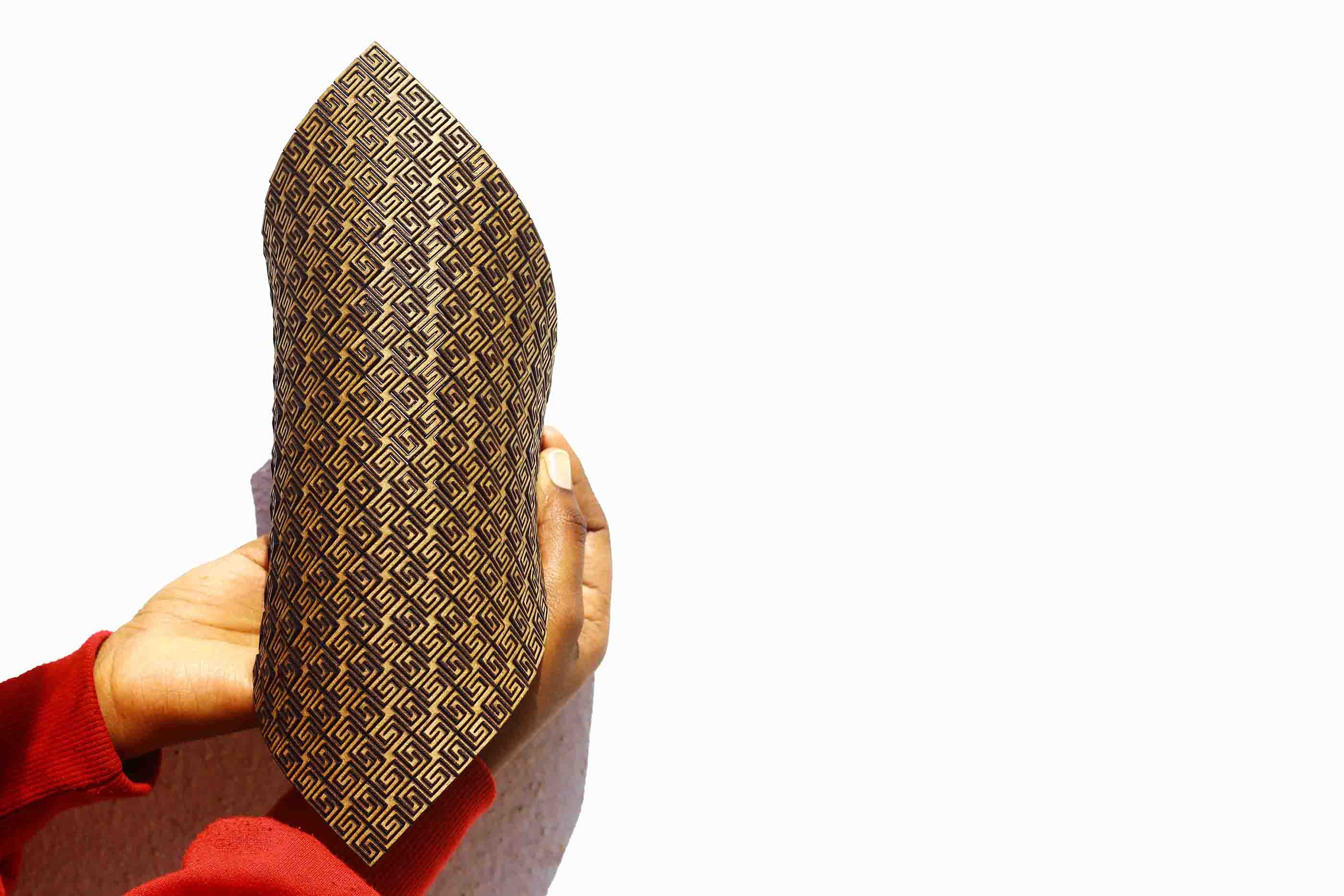
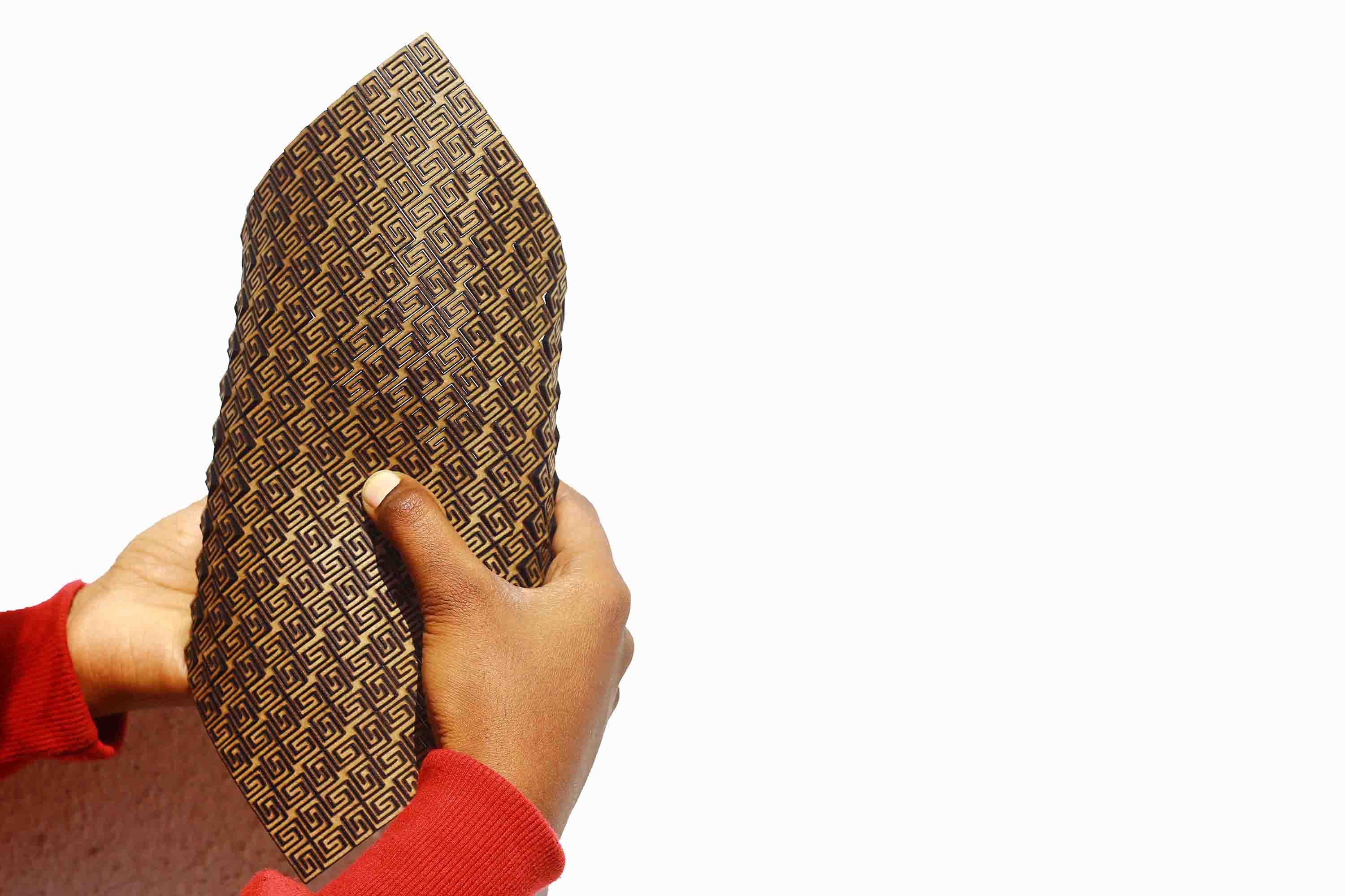
After laser-cutting a pre-designed living hinge, I decided to evolve it and create my own living hinge based on similar lines(one that could be bent and twisted in multiple directions). I have been obssesed with geometrical tiles for a long time and wanted to use a one of them consisting of parallelogram and square. Unlike the previous living hinge that used only one geometry getting reapeated, this tiling uses two geometries getting repeated again and again. These living hinges can be further evolved with some level of variations in geometry and lines. Also, one can observe as compared to the previous lasser cutting that the cuts are much better in terms of precision. This is a result because of the calibration of the laser.
Download the file here
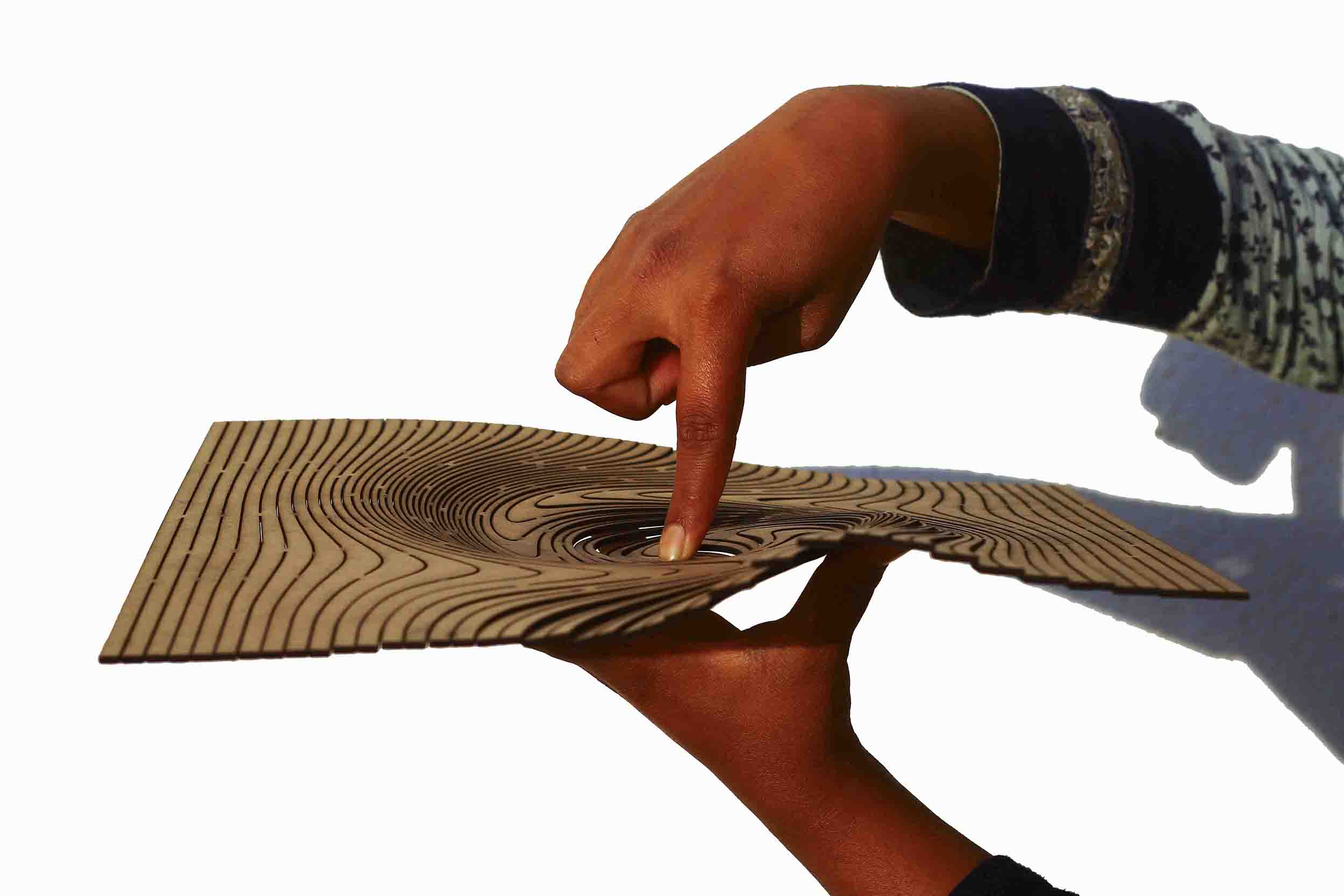
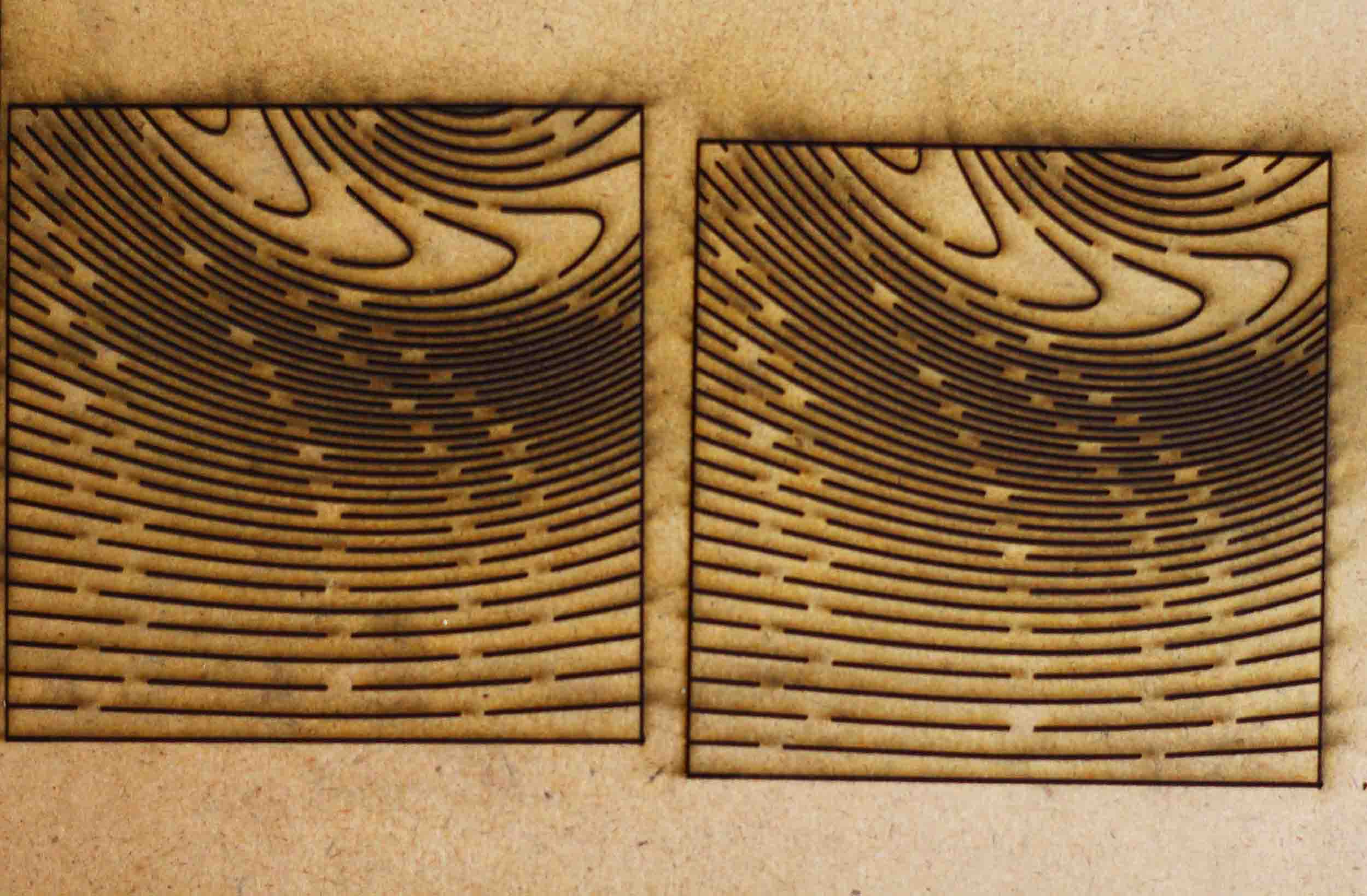
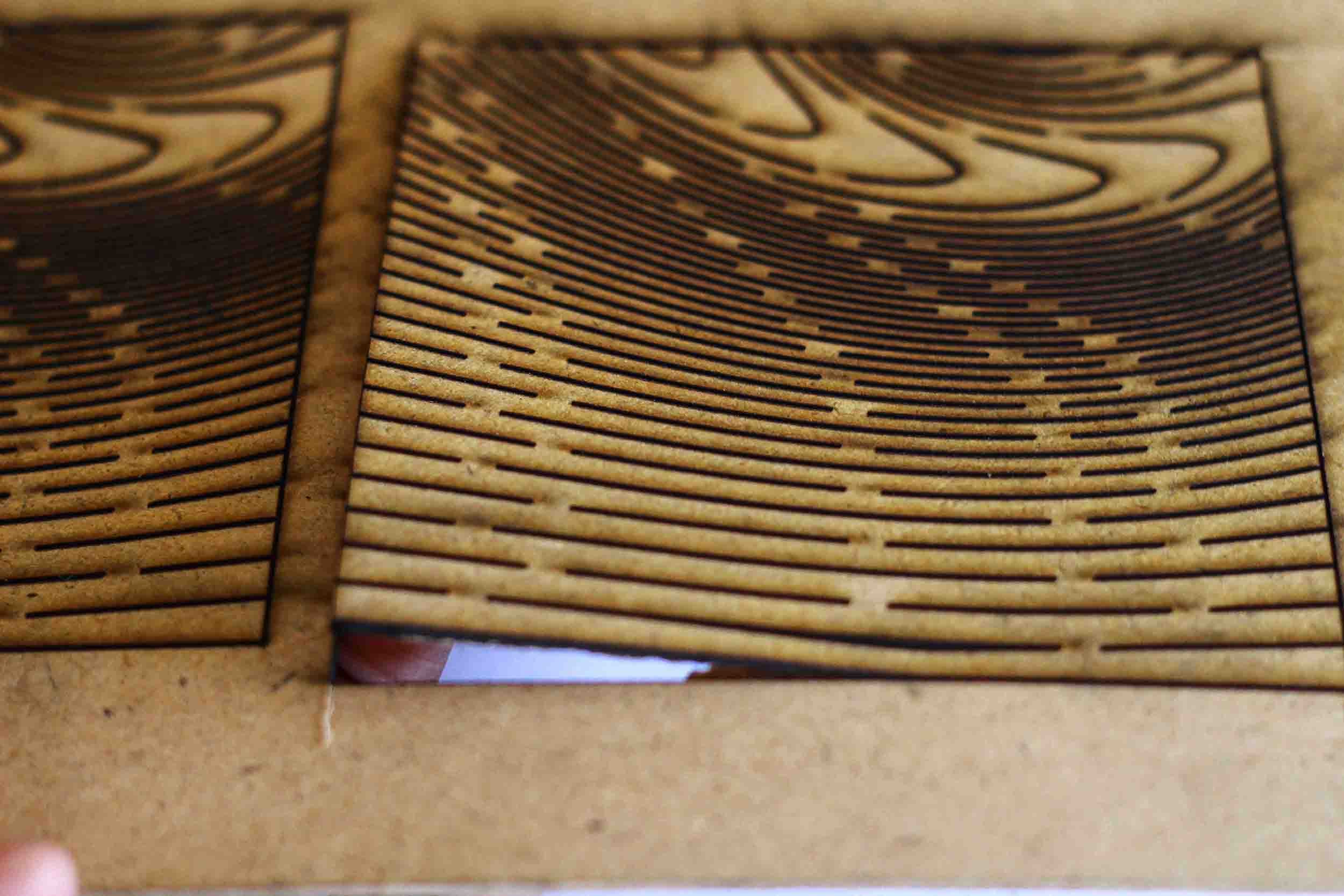
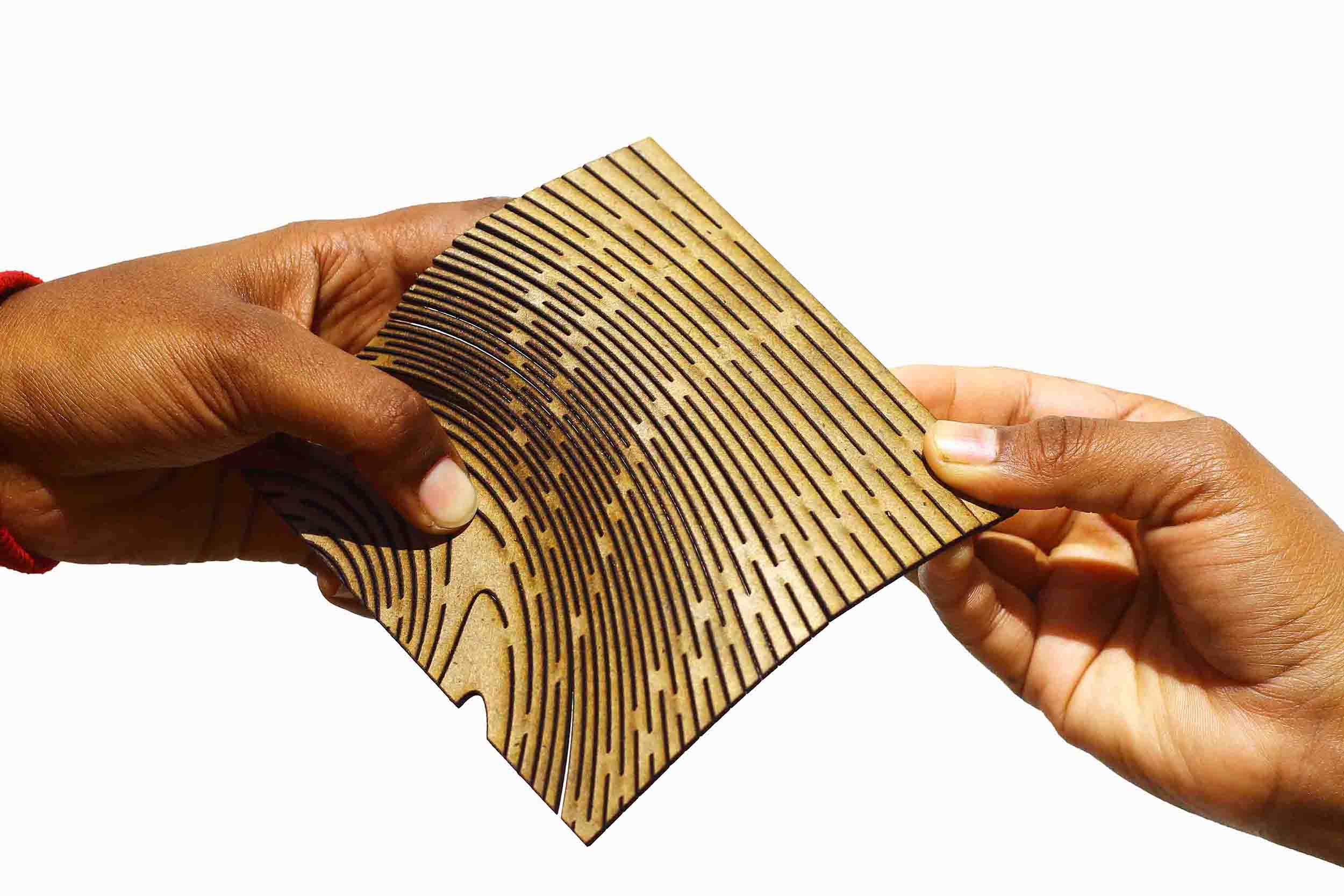
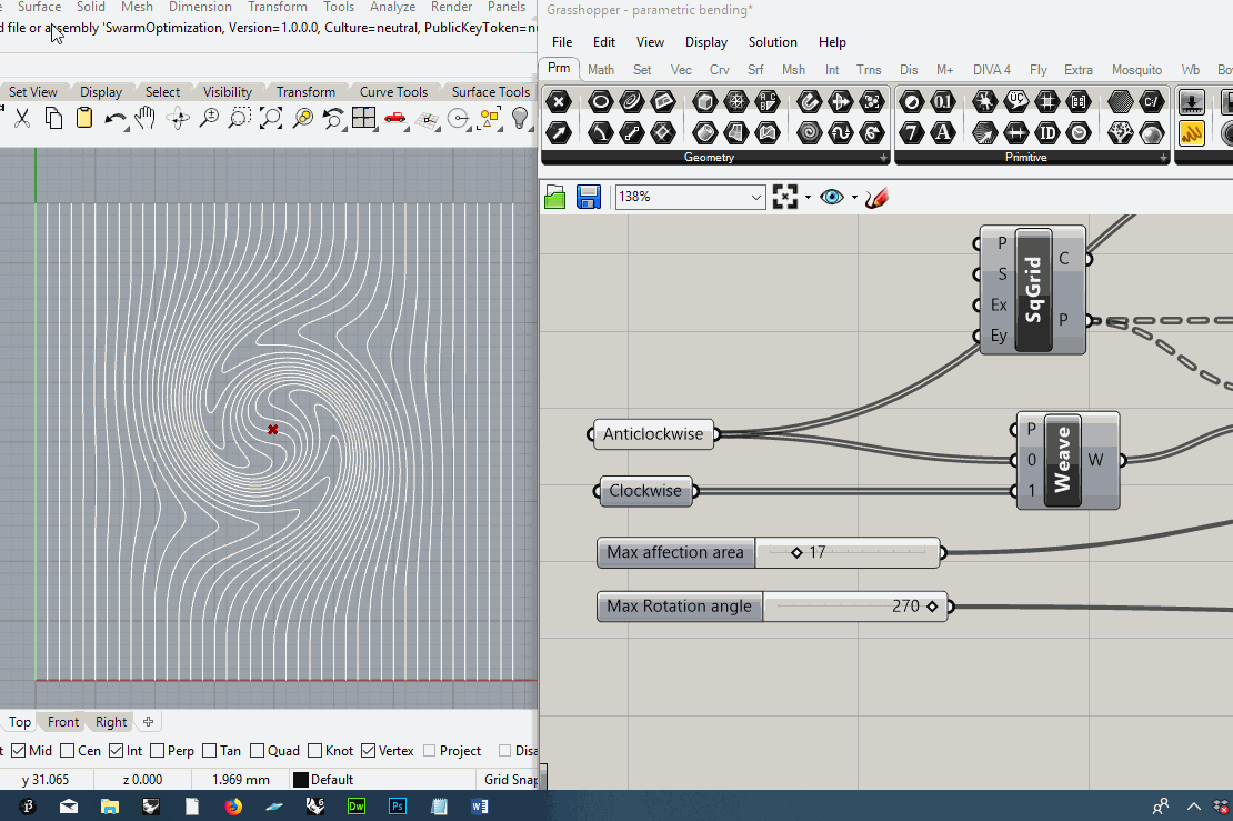
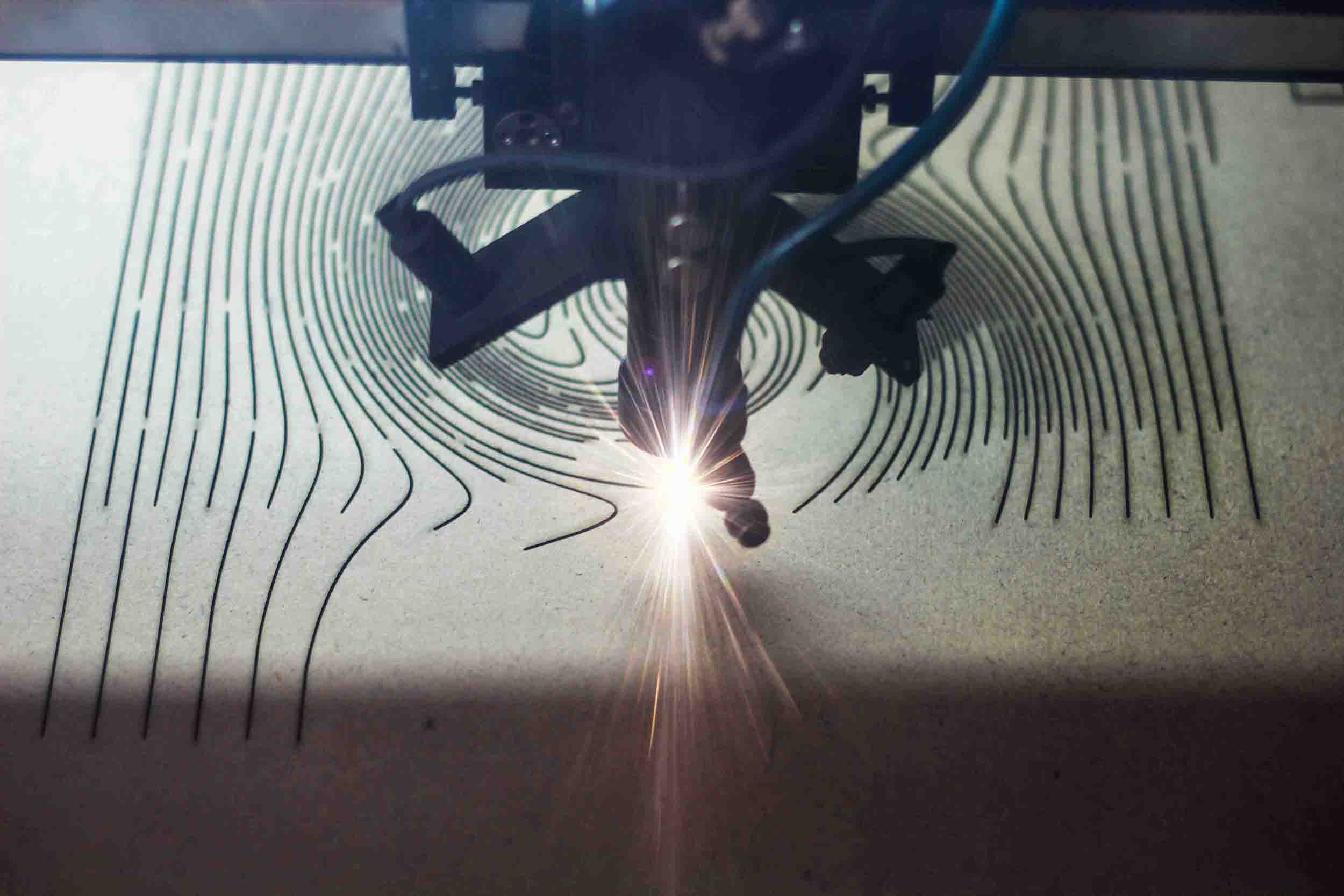
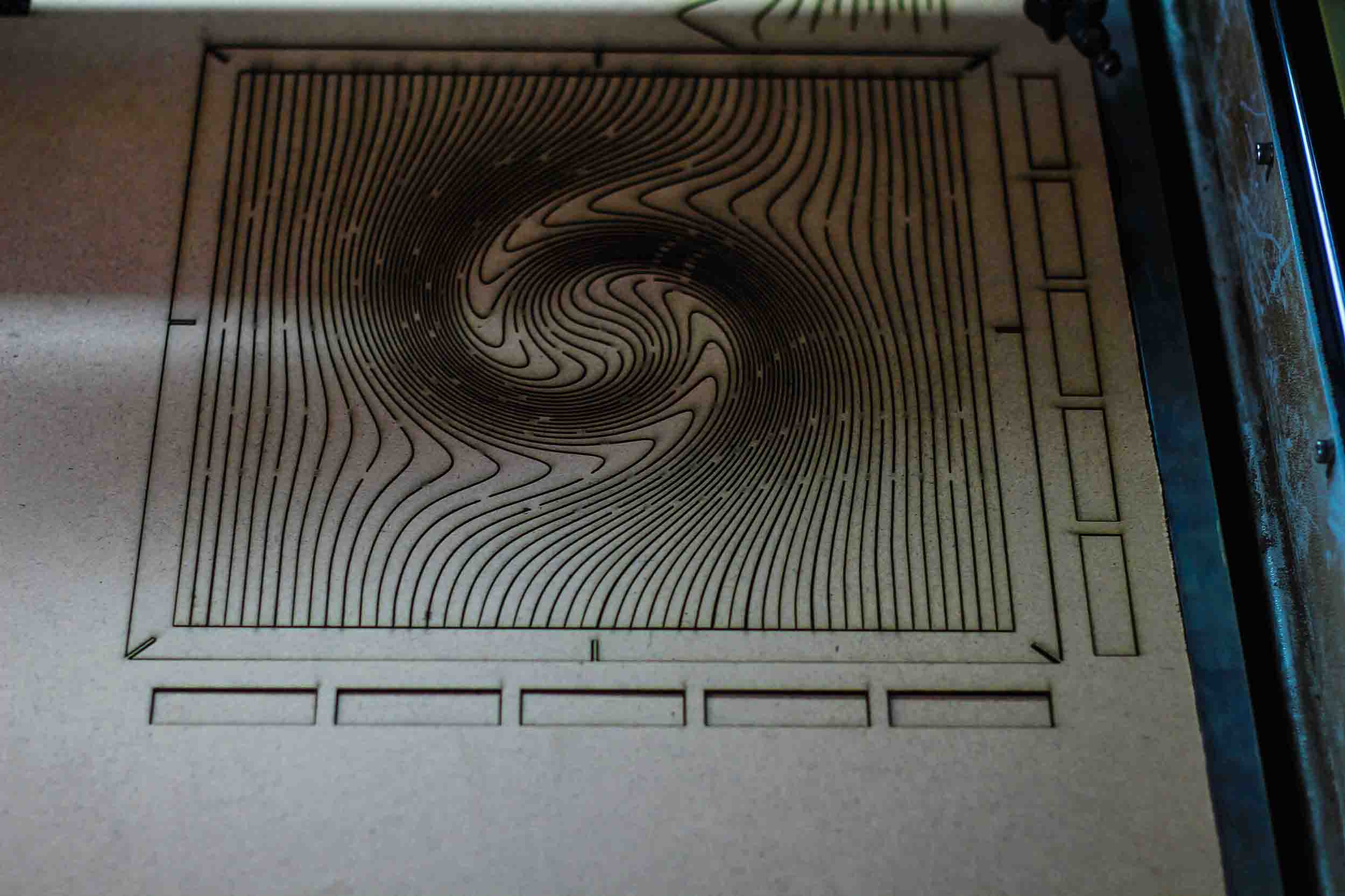
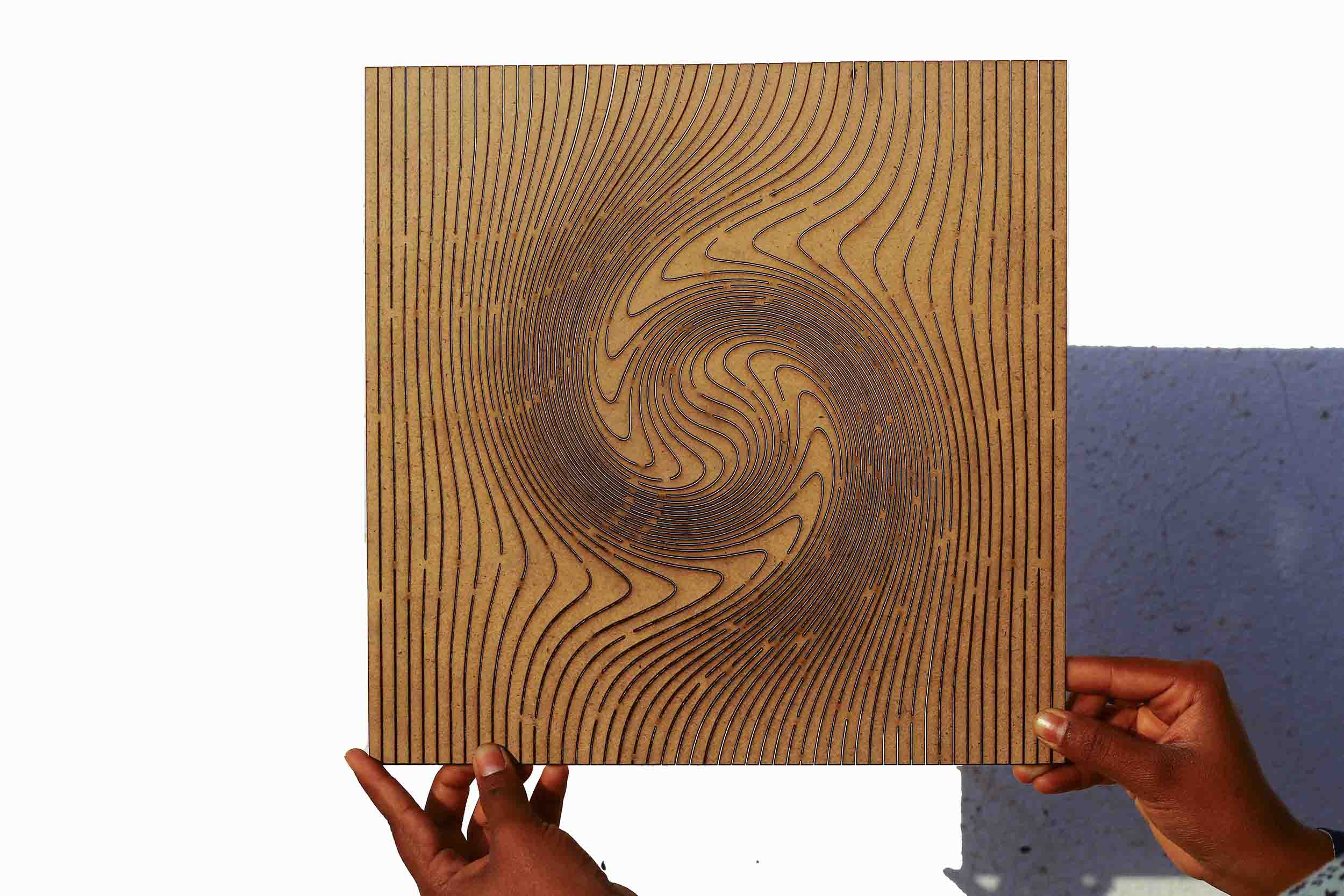
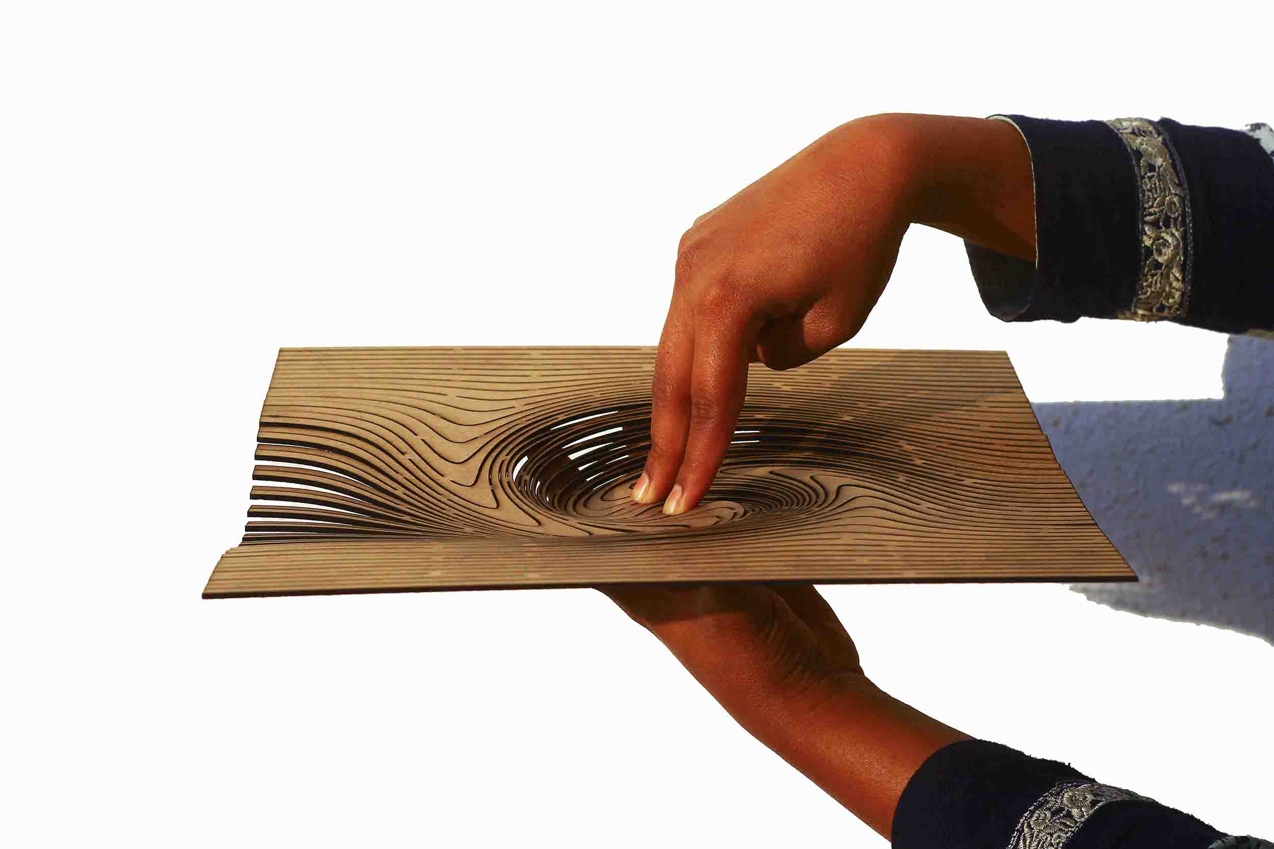
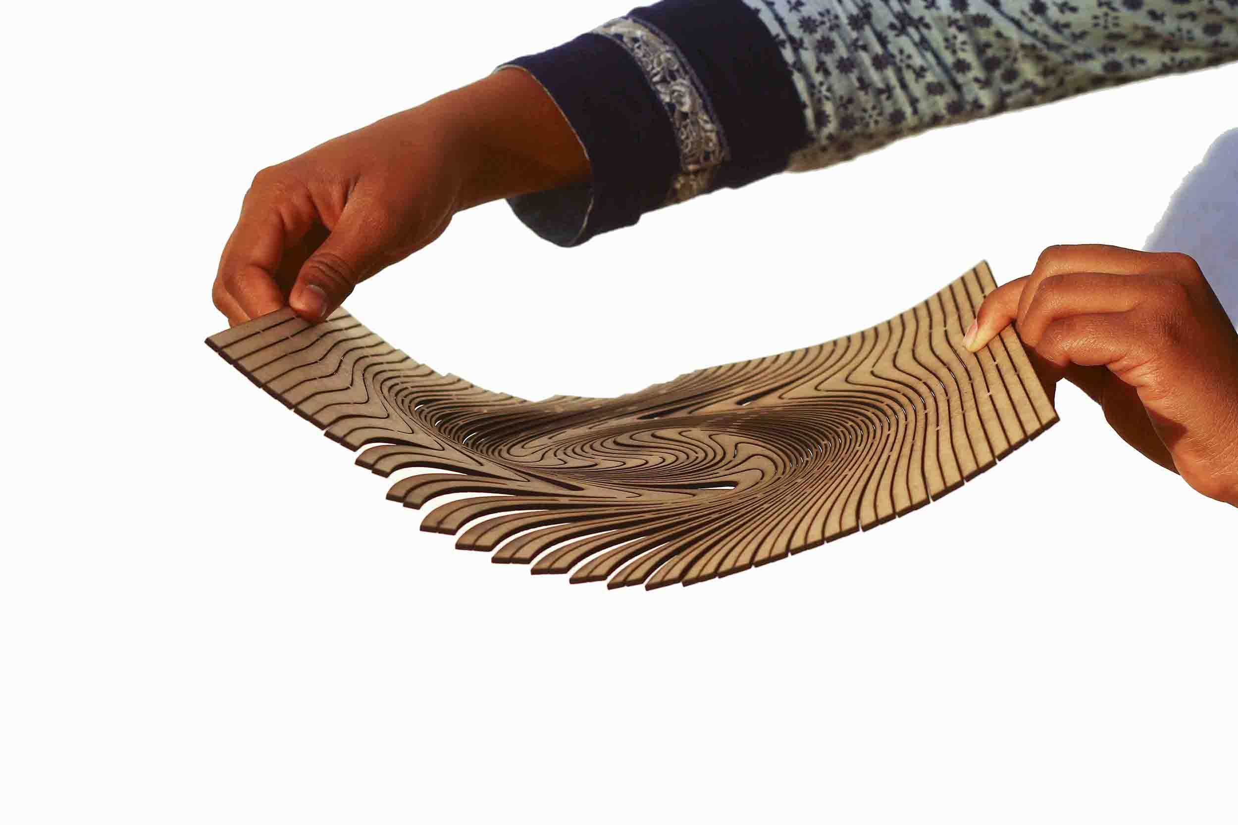
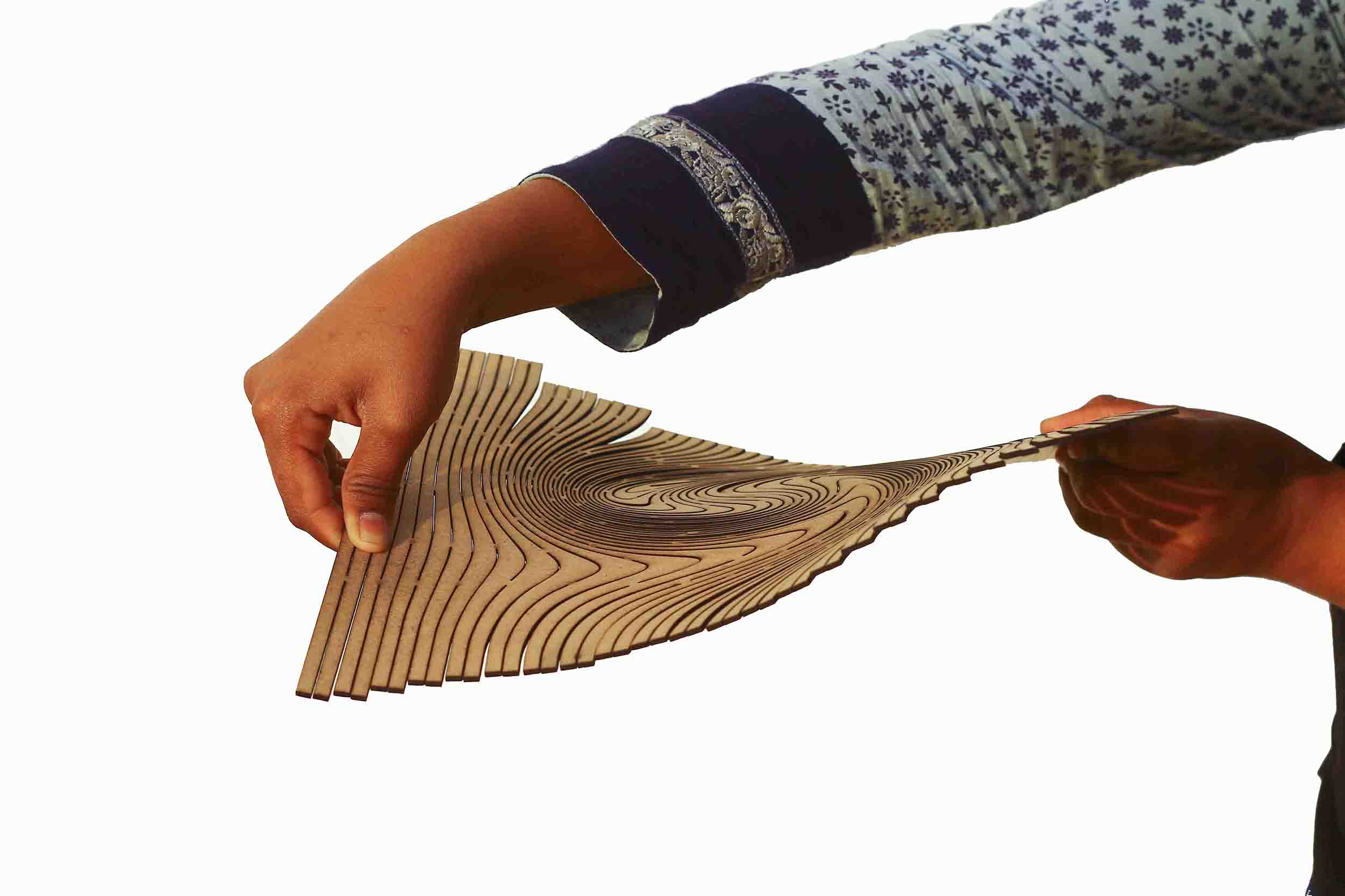
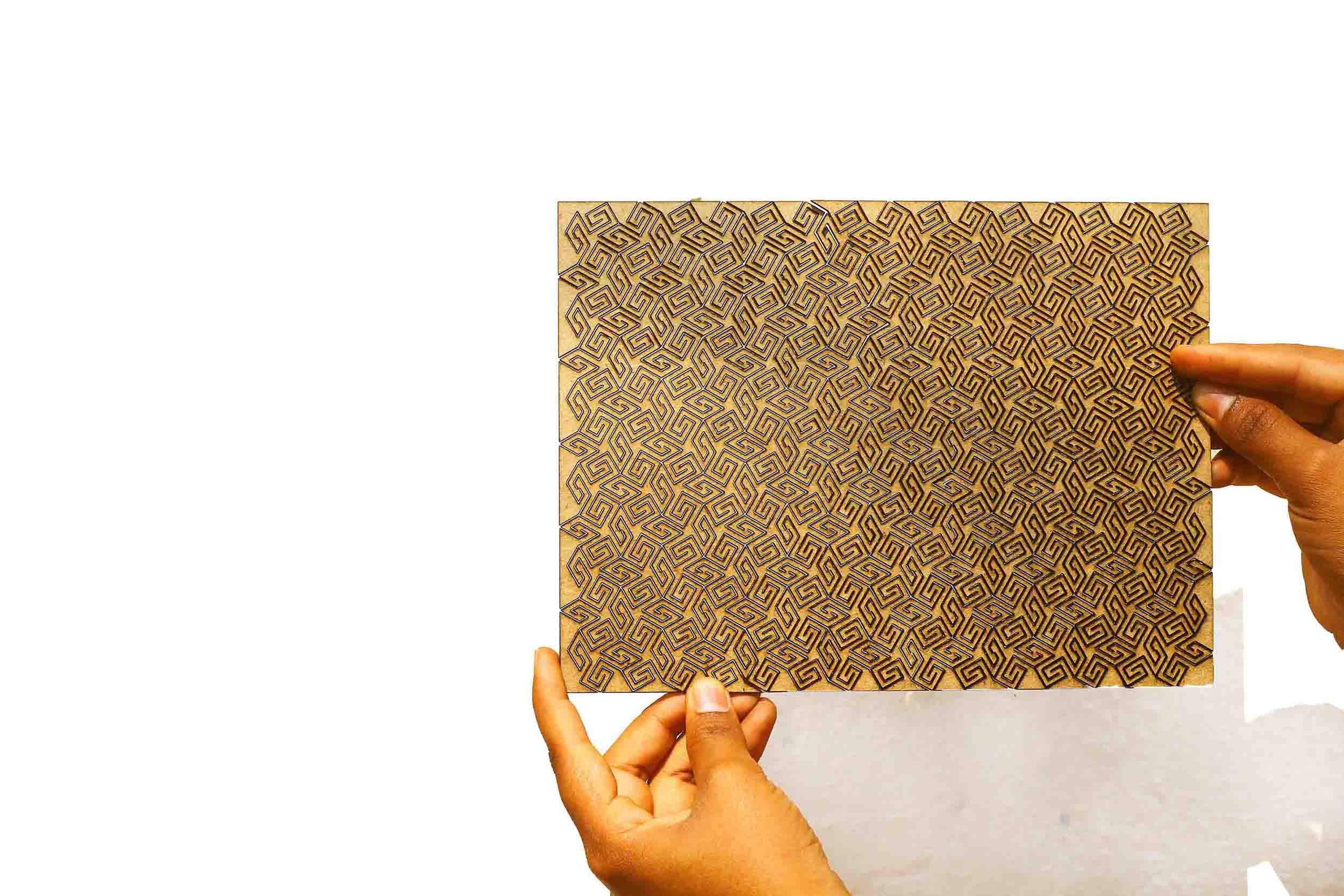
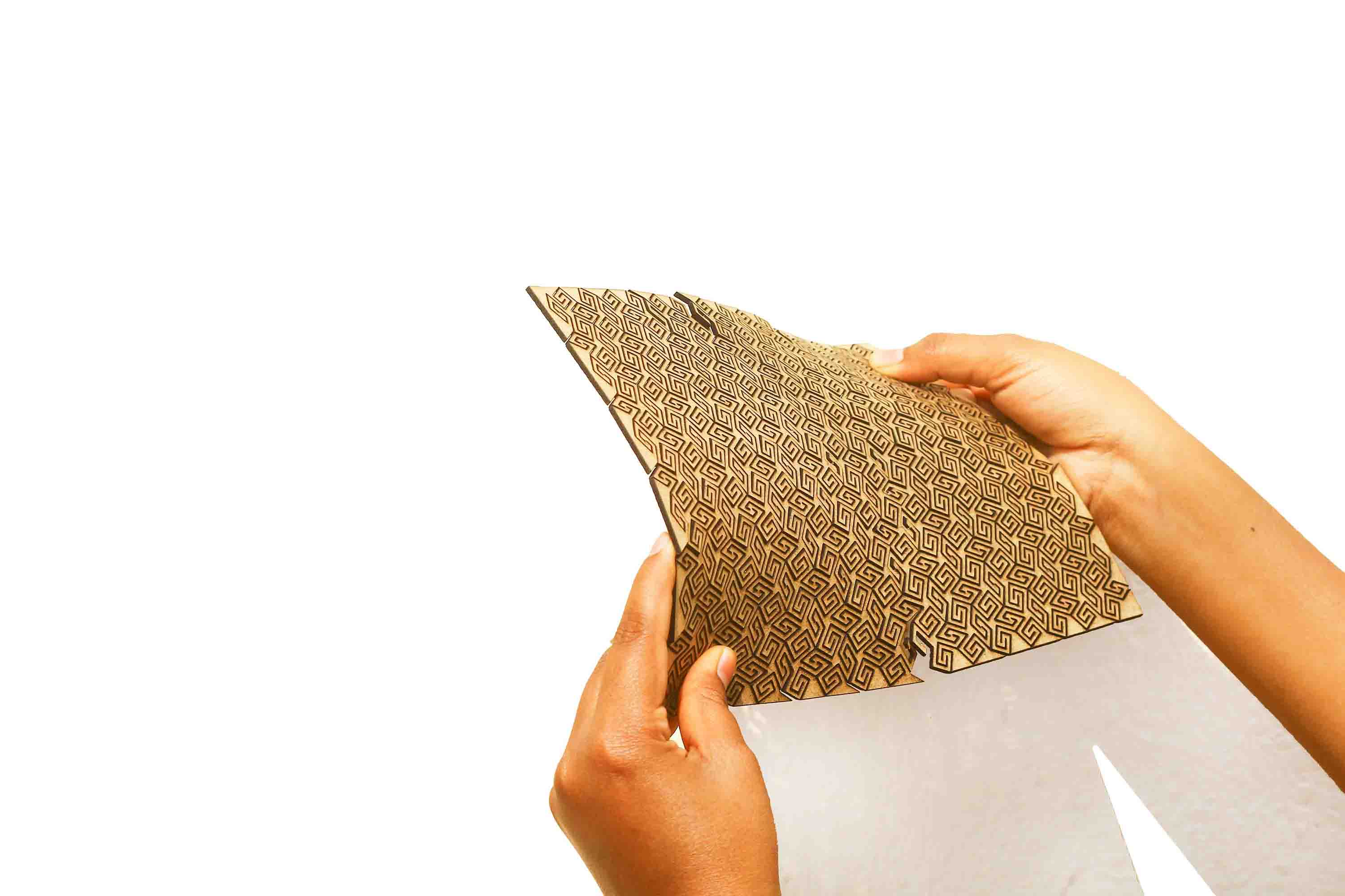
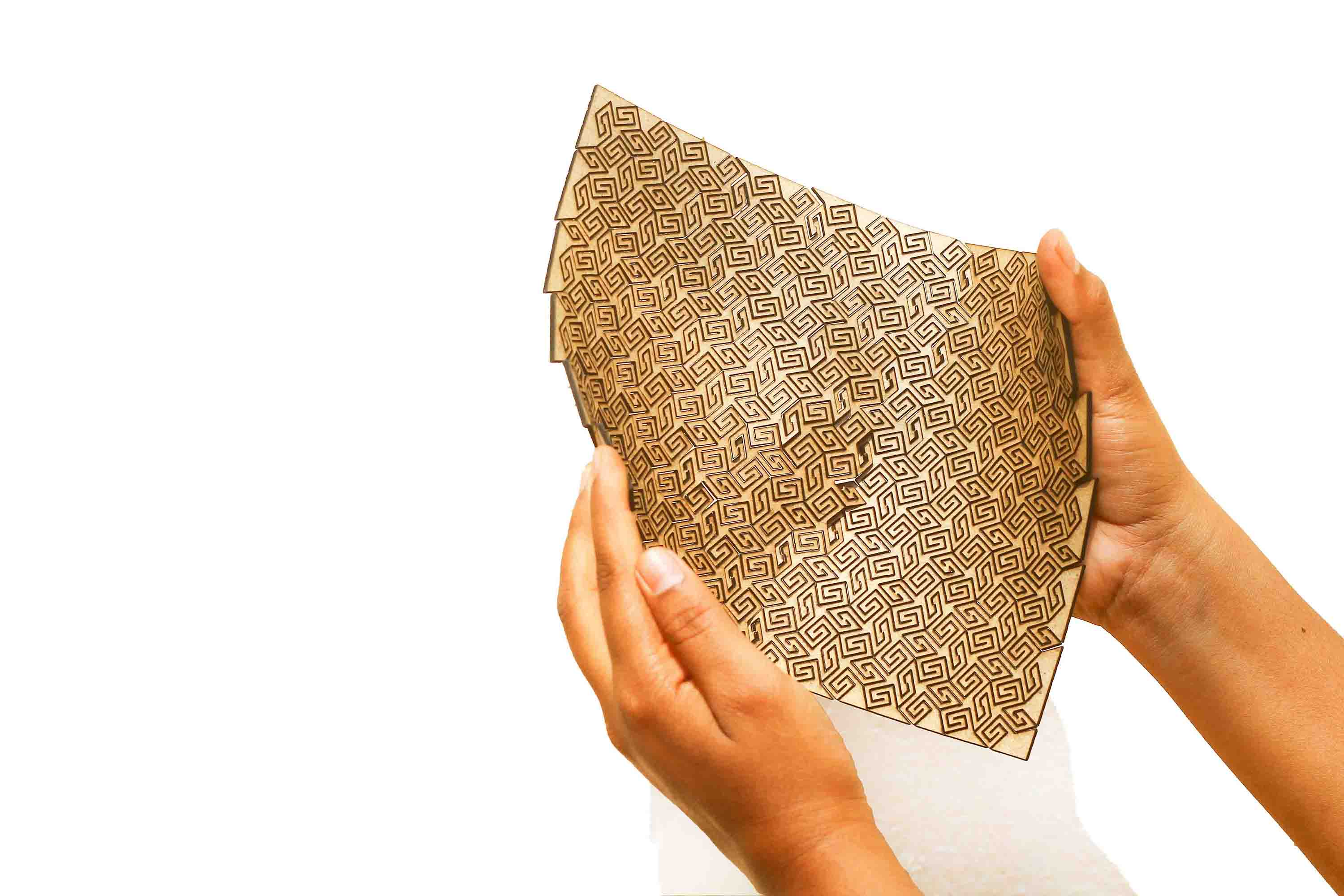
For my custom shape, I used straight lattice in the form of a whirlpool and started with cutting a part of it at a setting of 50W and 24 mm/s. The laser wasn't calinbrated and the pattern didn't cut properly, hence I had to go back to my previous tried and tested setting of 60W Power and 10 mm/s speed. I had to force a bit to take the pattern out. Since it was a whirlpool and it would be bent in a certain way when the pressure is applied to designated places, it was doing so and I was satisfied with it. I also did certain changes for the final cut. I made the cuts longer and calibrated the laser cut machine(by local instructor Suhas Labade). I also found out that closer the lines, the more the elasticity. One important aspect here to pay attention to the fact that the space left between lines has to be in an alternative zig-zag manner.
Download the file here
The following links helped me in understanding bending, curvature and torsion
a. Bending Radius
b. Understanding Curvature
Press fit construction
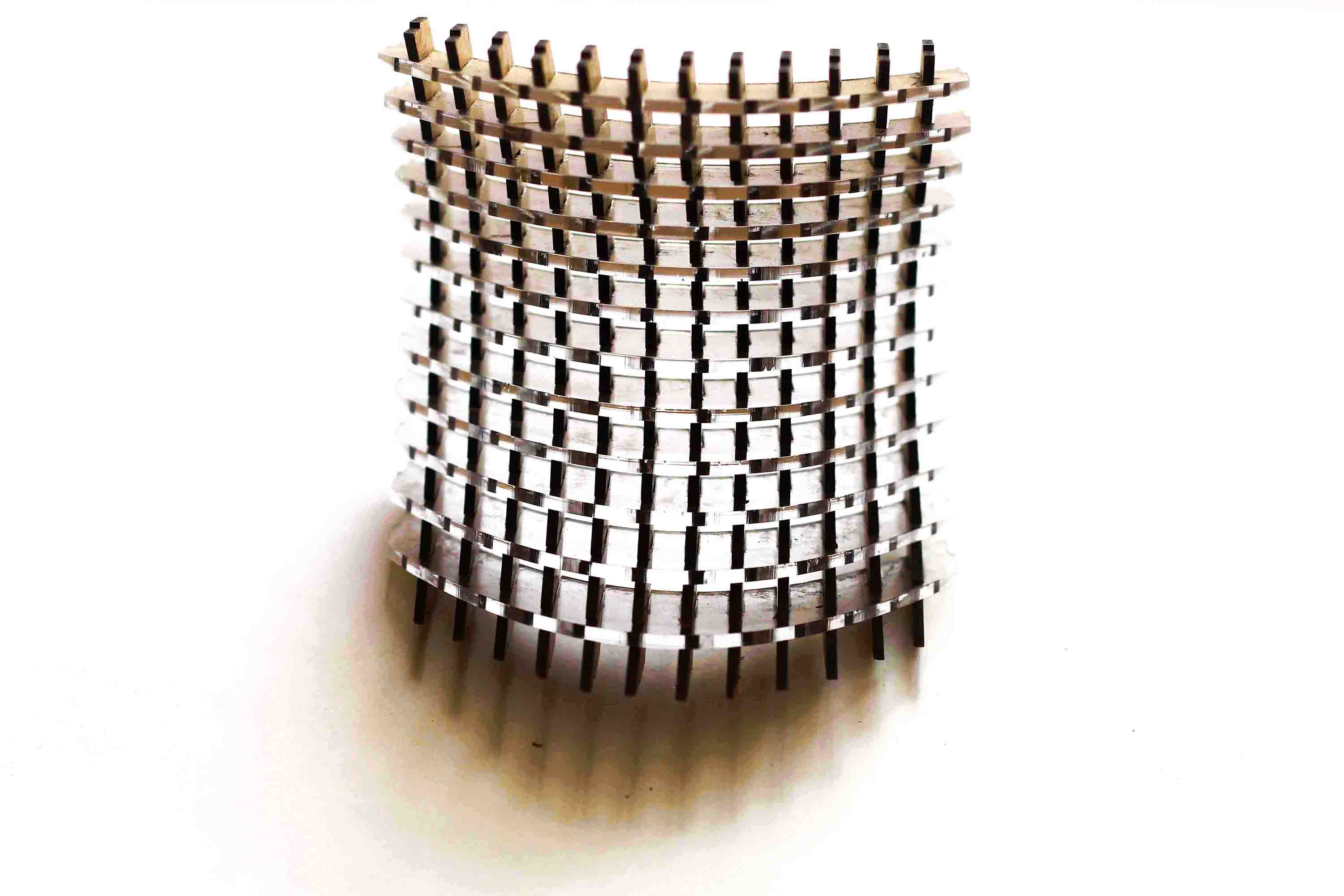
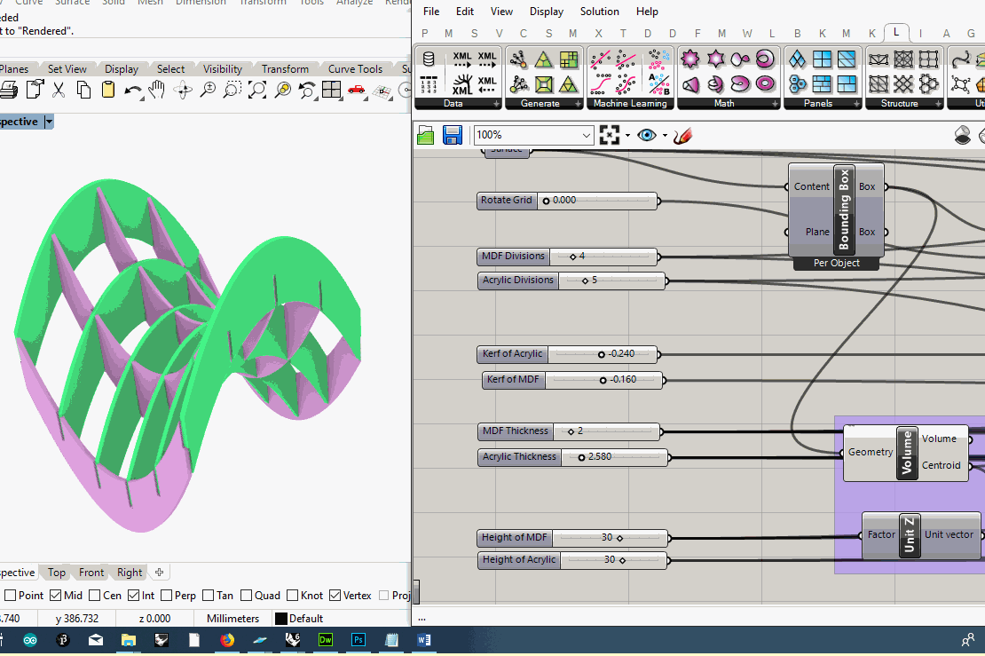
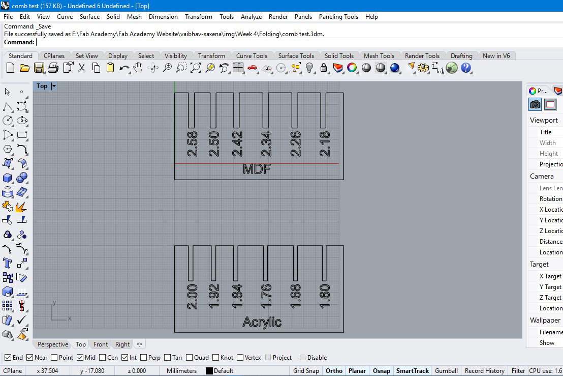
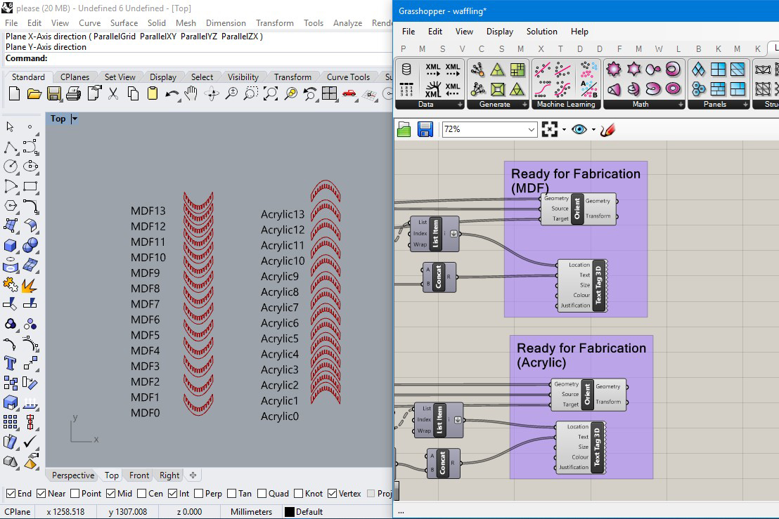
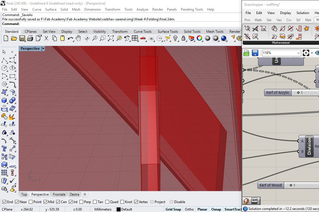
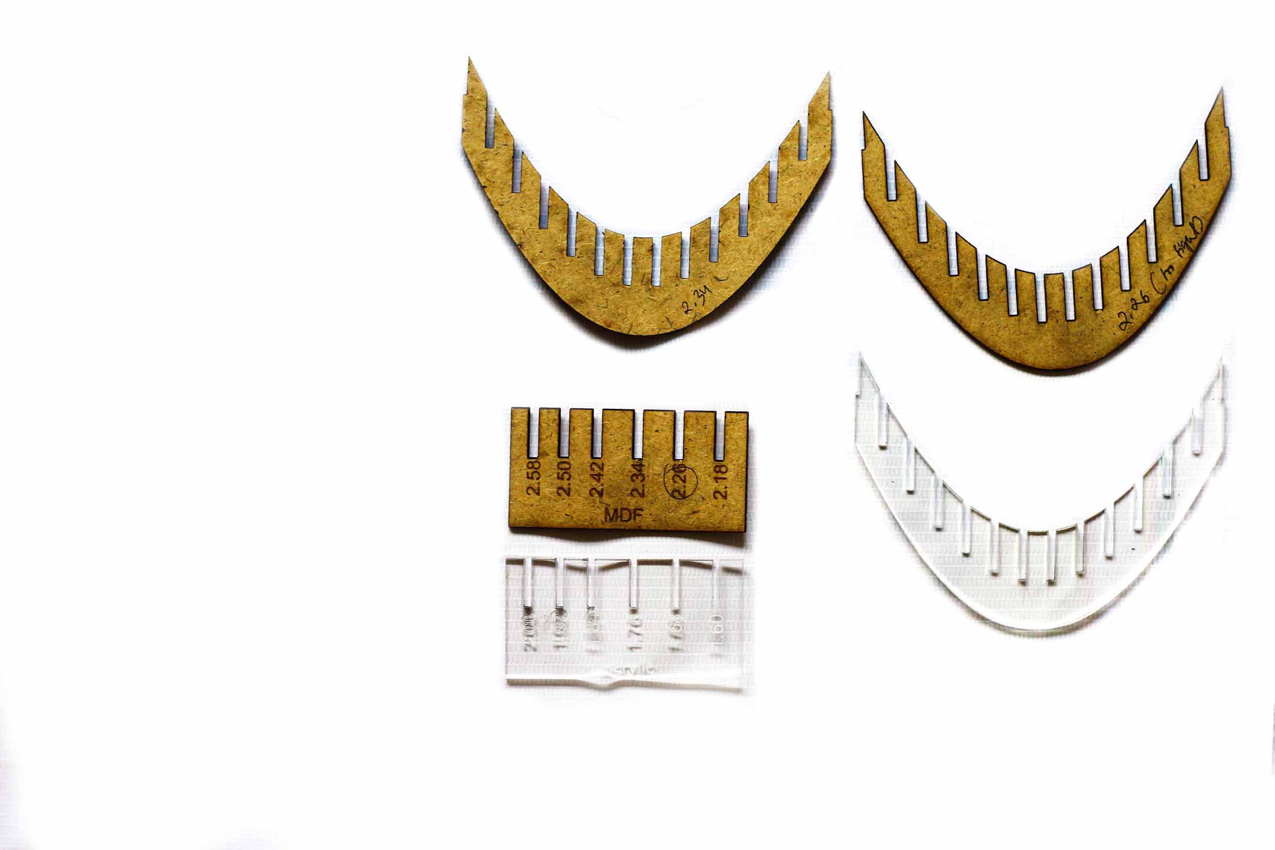
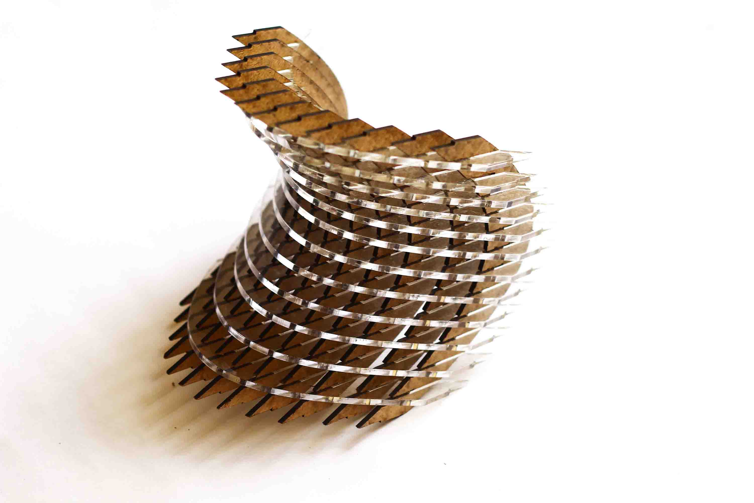
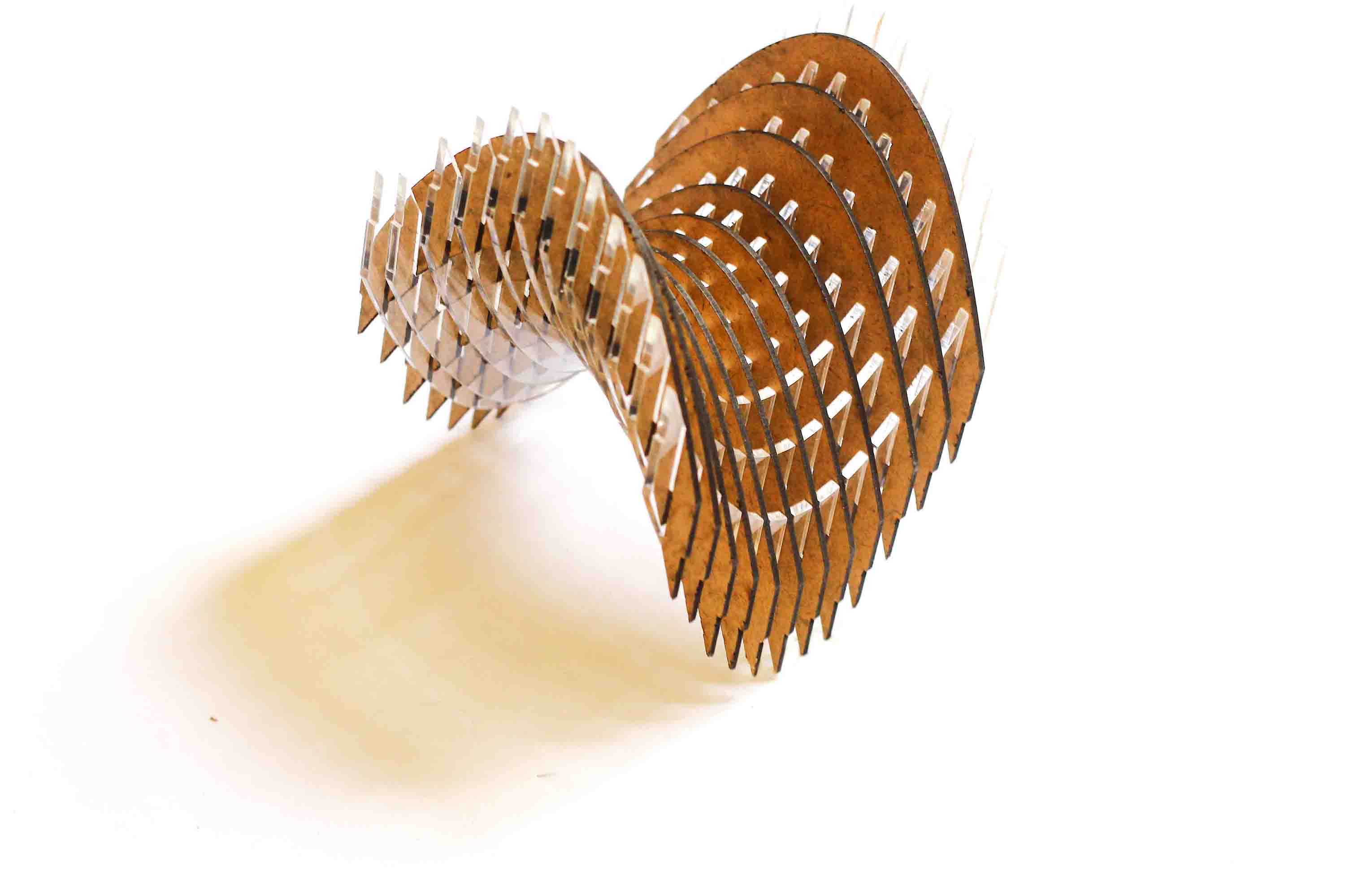
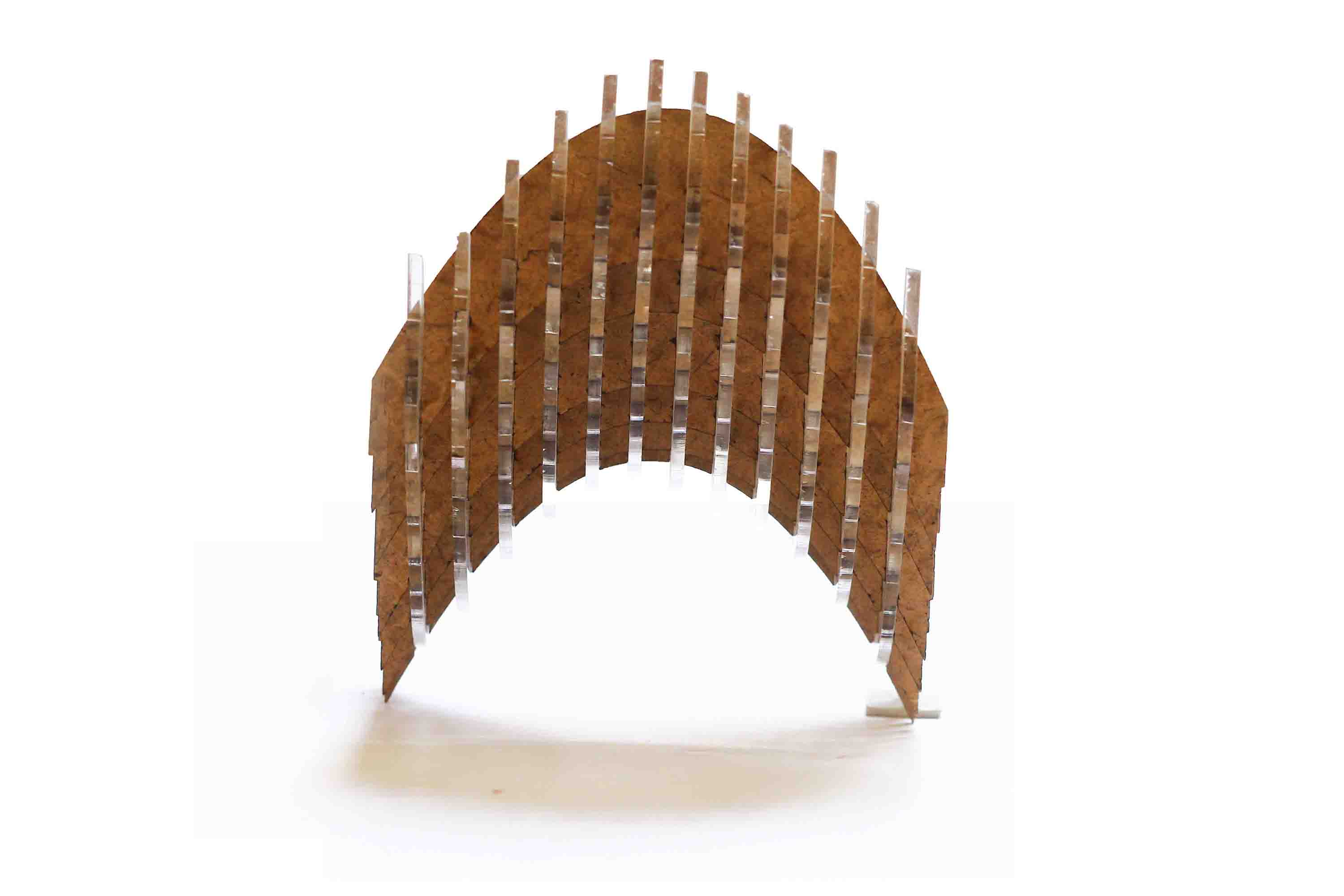
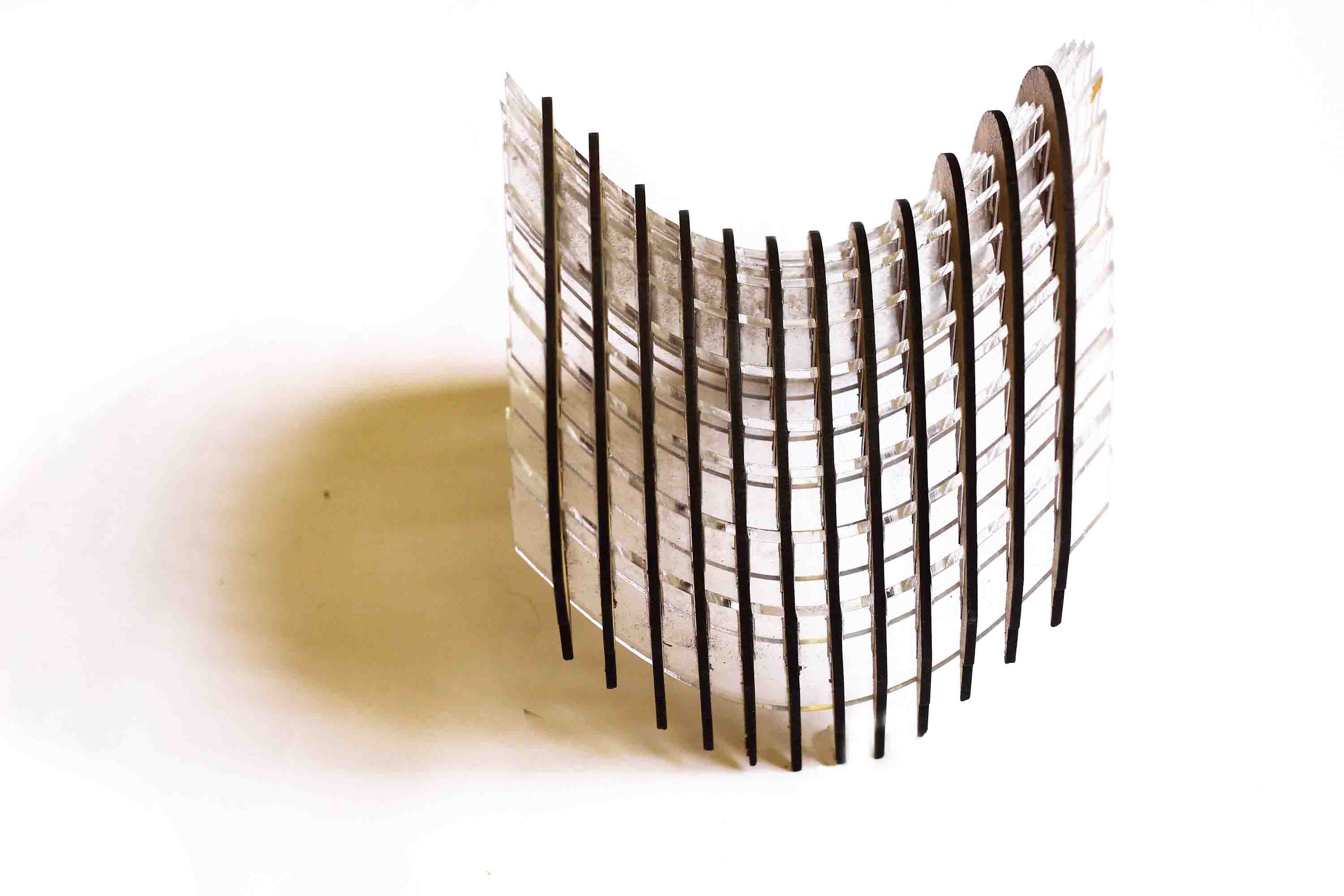
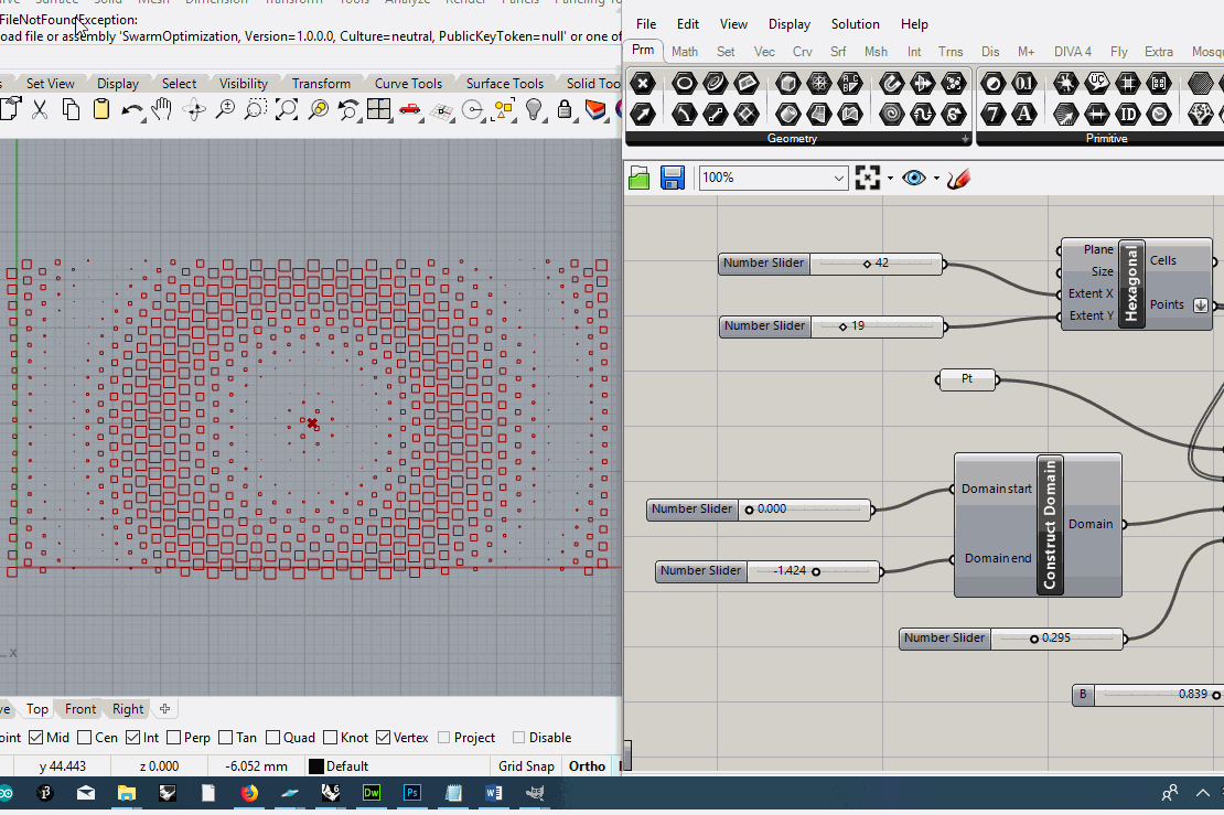
I wanted to create a waffle/rib structure on a doubly curved surface using Grasshopper(again) for the press fit assignment. This might seem a very common thing around, but most of the scripts available online didn't include the kerf. Also, I wanted to make the waffle/rib structure using two materials i.e. MDF and acrylic, hence I had to use comb test to check which settings fit in properly. MDF is 2 mm and Acrylic is 2.58 mm thick respectively. While performing comb test, on both MDF and acrylic, I took increments of 0.08 mm based on kerf. The comb settings that allowed for perfect snuck fit are:
2.26 mm for the acrylic on MDF, and
1.92 mm for MDF on acrylic.
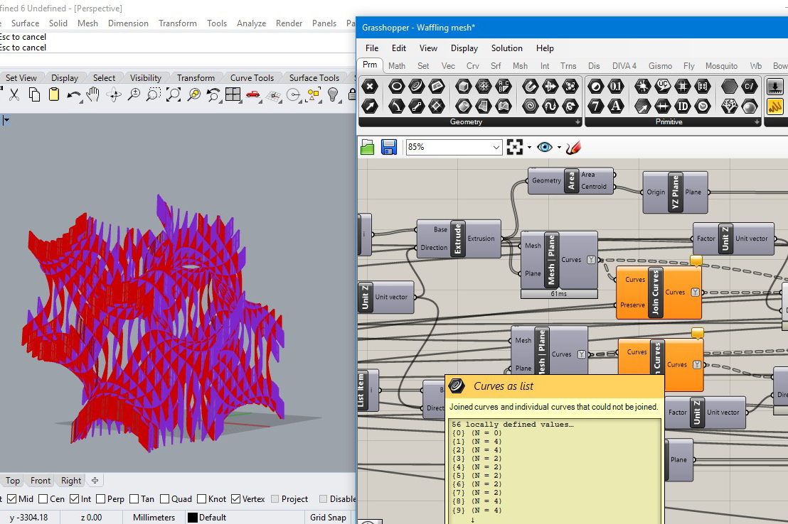
I further went ahead and tried to apply the script on a gyroid surface, a minimal surface as mesh in Grasshopper, but since it was a mesh and my script only took inputs as "surface" it failed to generate a ribbed structure. But then I decided to create some changes in the mesh but still there were some issues with the script and it failed to create the final product intended. I also realized that having so many parameters in a script/code helps in more control over changes to be done in the future. I made the script, fabrication ready, hence the workflow was faster.
Download the Grasshopper code here and 3d file here