Week 5
The fun with electroincs started
This week will start learning how to design PCB for electronic ciructs as we need . First we have select to make ISP.
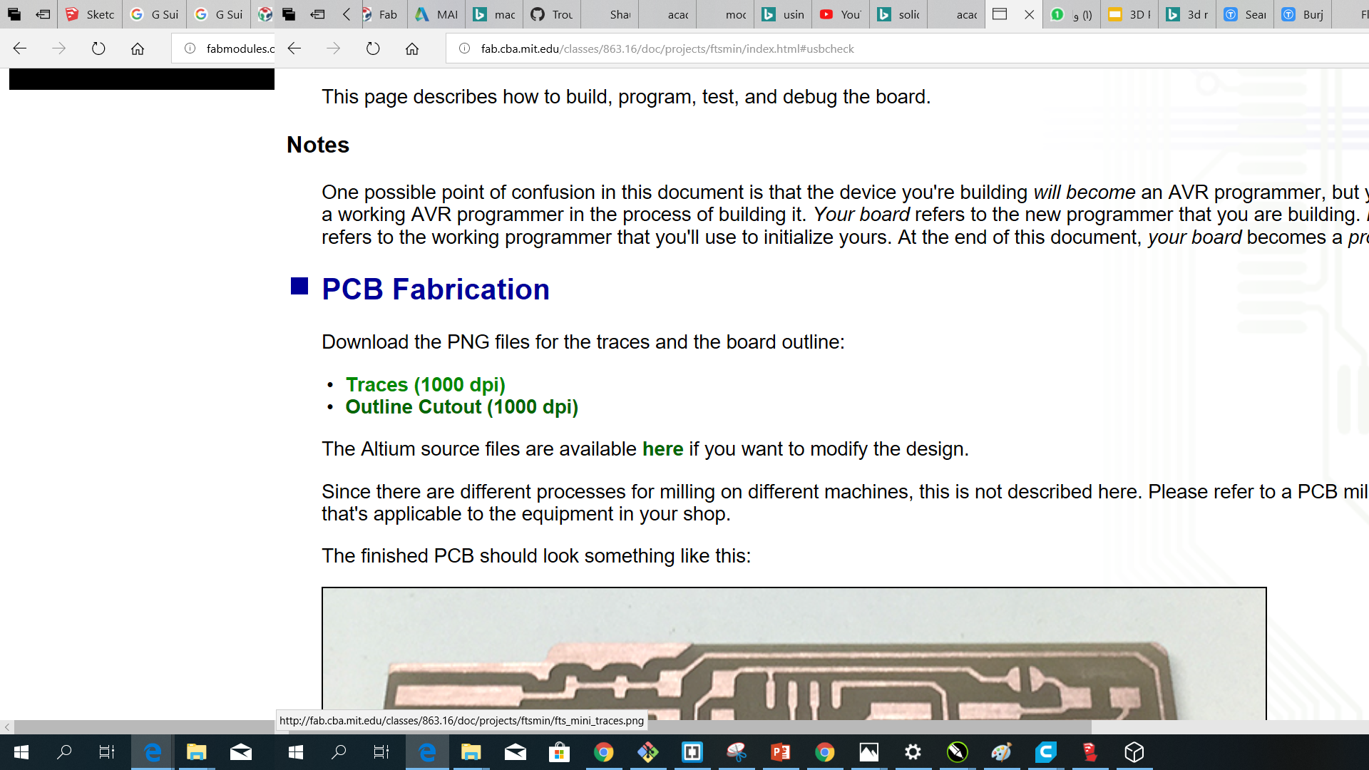
PCB Fabrication
first we Downloaded the PNG files for the traces and the board outline:
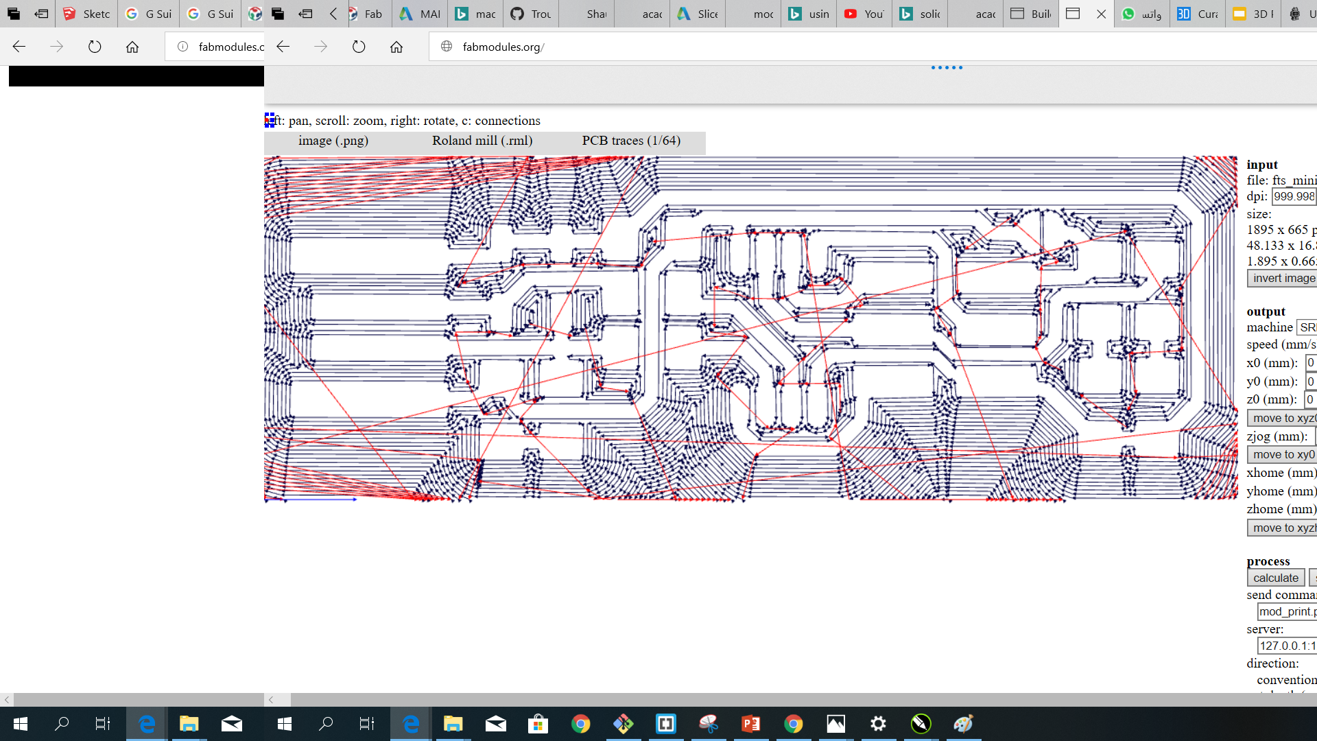
Then we use fabmodules.org to calculate our machine miller pathes by selecting the trace image first then modify the settings
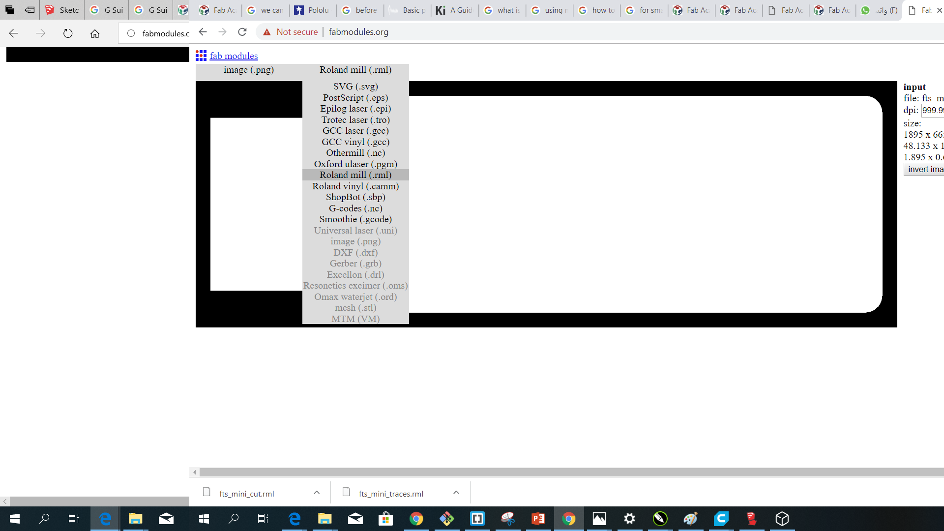
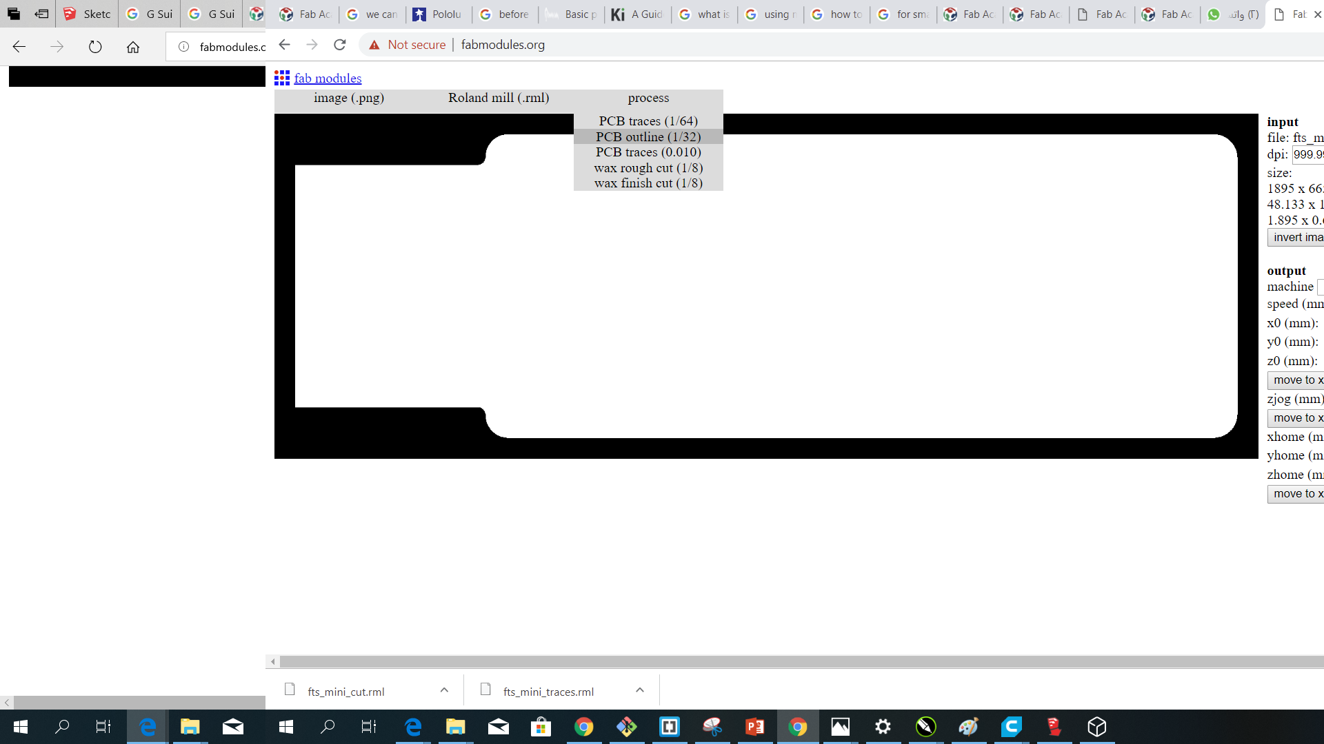
we modified some setting such as changing the offset to -1 as its the best for engraving quiality after testing with defult value.
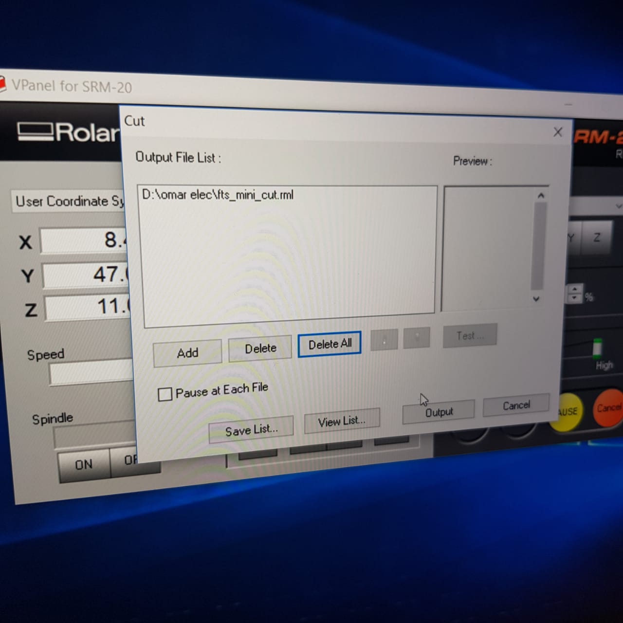
then we save the both files in our usb memory to take for printing in the Roland SRM 20 Milling machine
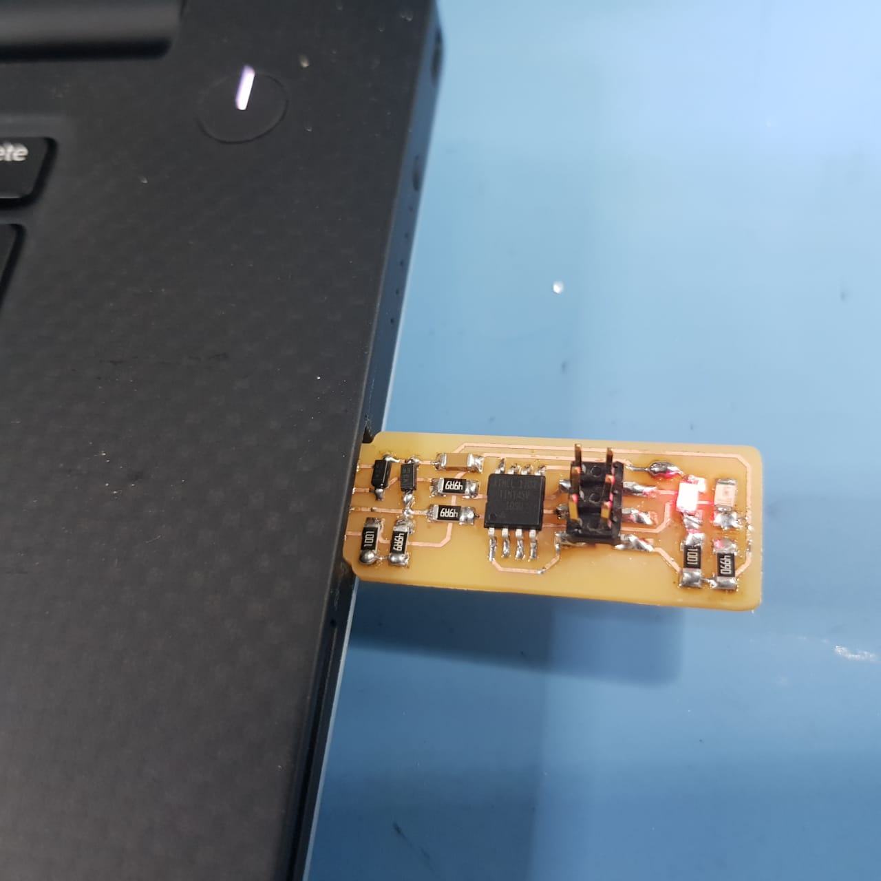
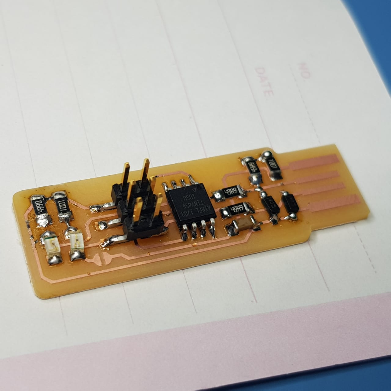
A wide range of materials, including modeling wax, chemical wood, foam, acrylic, poly acetate, ABS and PC board can be precision milled using the SRM-20 small milling machine, allowing you to create realistic 3D prototypes that are virtually identical to production parts. So we used it for milling our ISP USB connector Board.
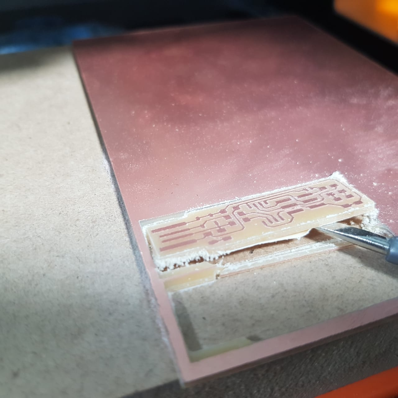
the Milling started
First we fixed the copper board with taps on the base of the miller and then we started with head changing and resetting the z axis for it. Then we reset the x amd y axis also so we do not waist too much of our board.
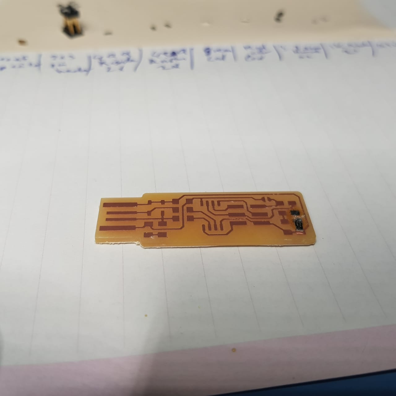
The first was engraving the trace. Then after cleaning the board we start the cutting with head size of 1/32.
Under process
the guid for gathring all items guide.
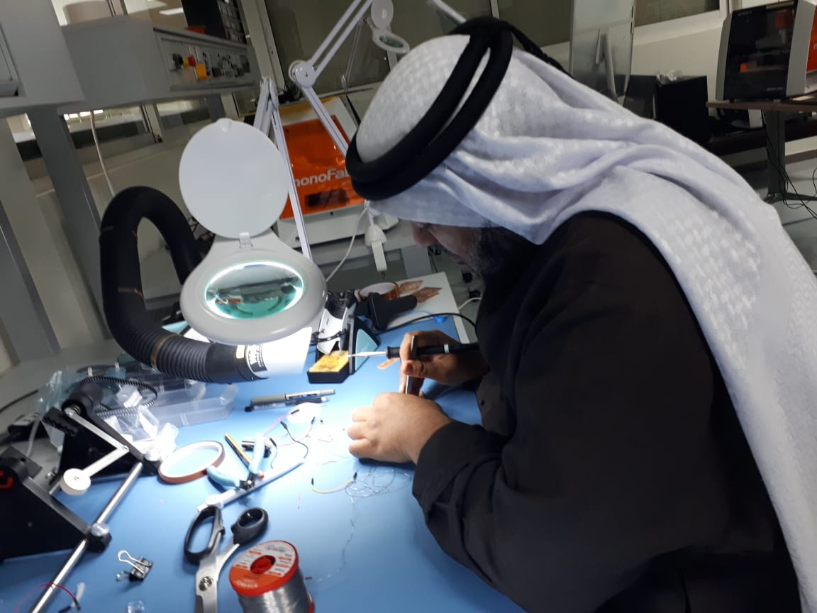
the coding
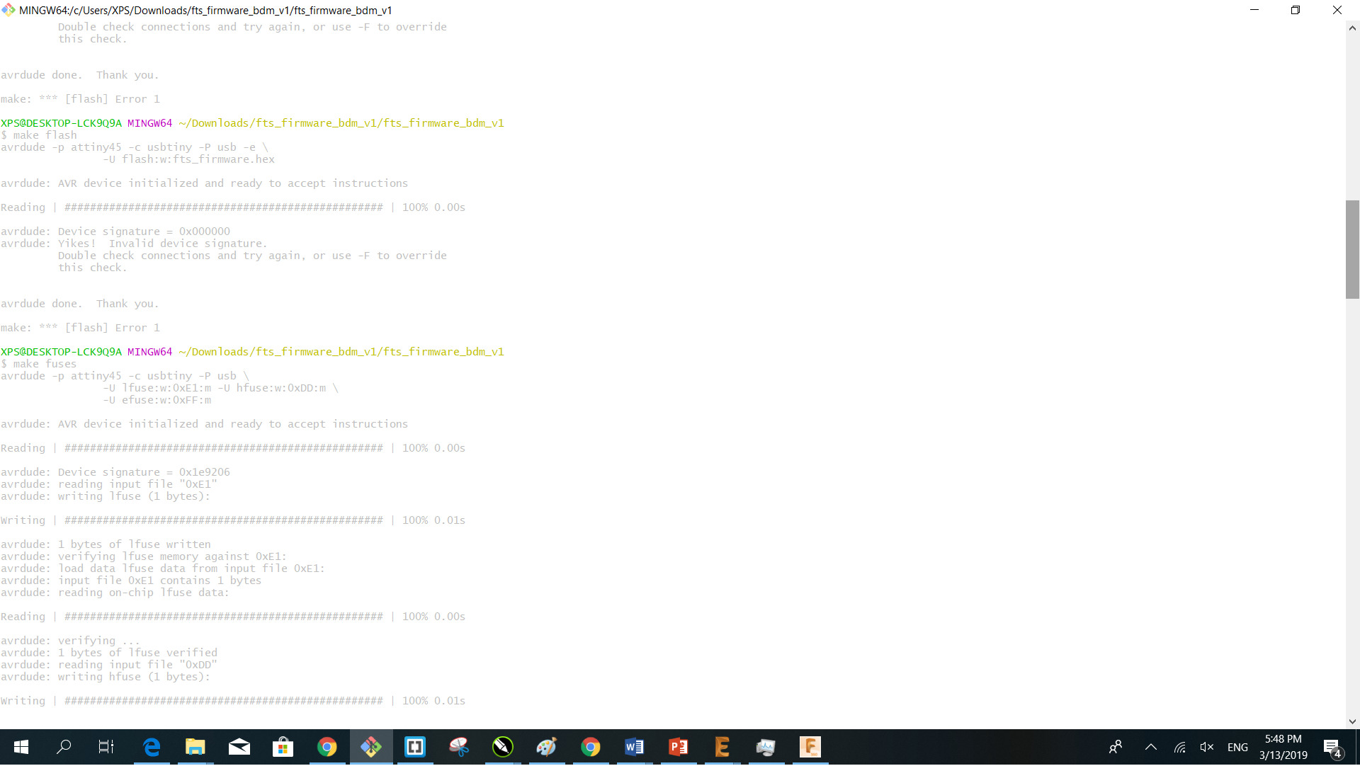
Following steps on guide we must download the firmware then using Git we use the following commands:
make flash
make fuses
make rstdisbl
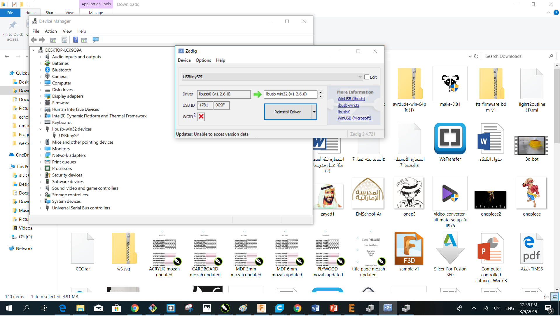
Preliminary steps before starting to program the FABTinyISP is to check that GNUWin32, avrdude, and avr8_gnu_toolchain recognized by the path.