Week 6 - 3D Scanning and Printing: How to print 3D printed objects and 3D Scan objects.
Posted on February 6, 2019
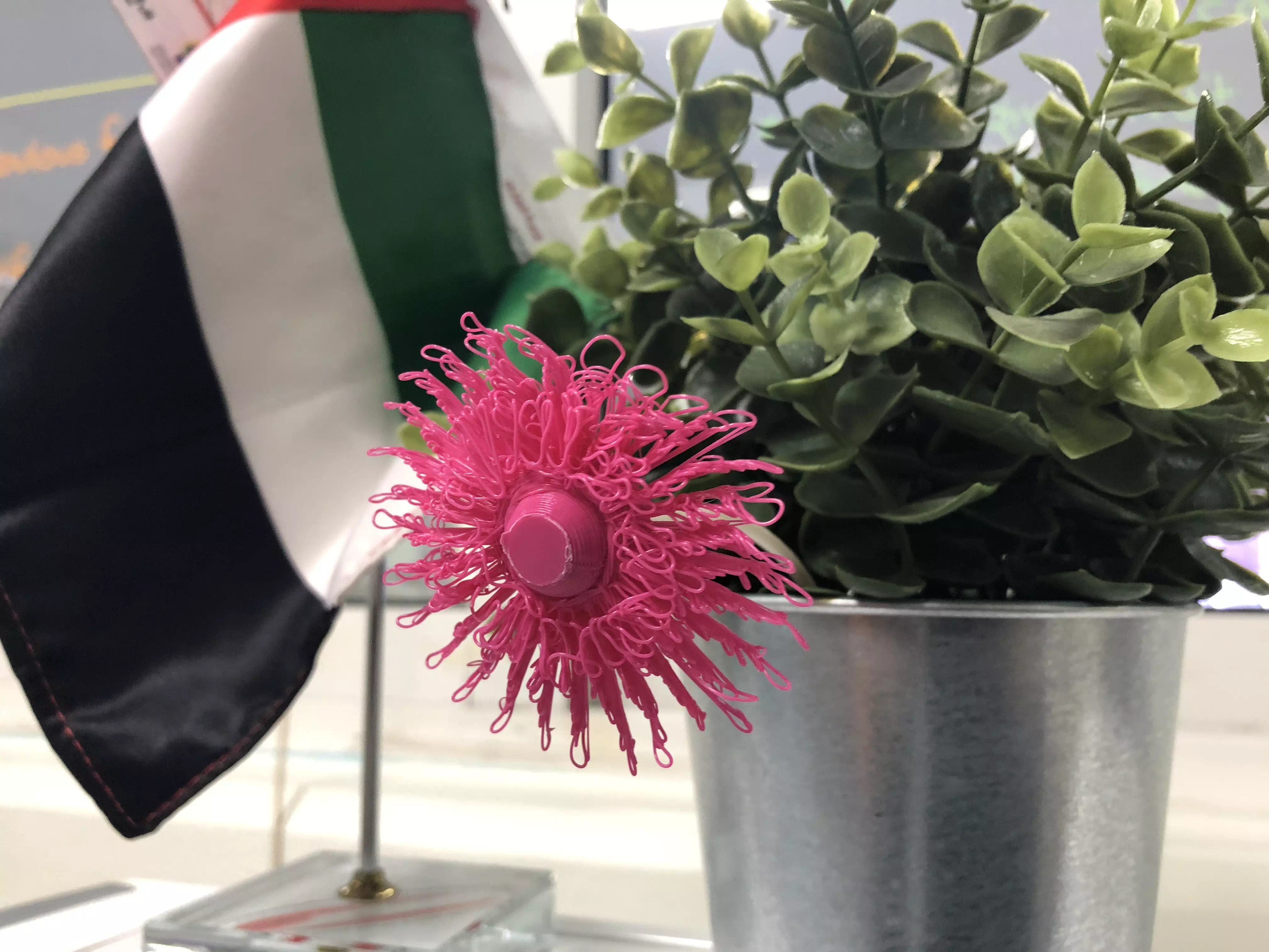
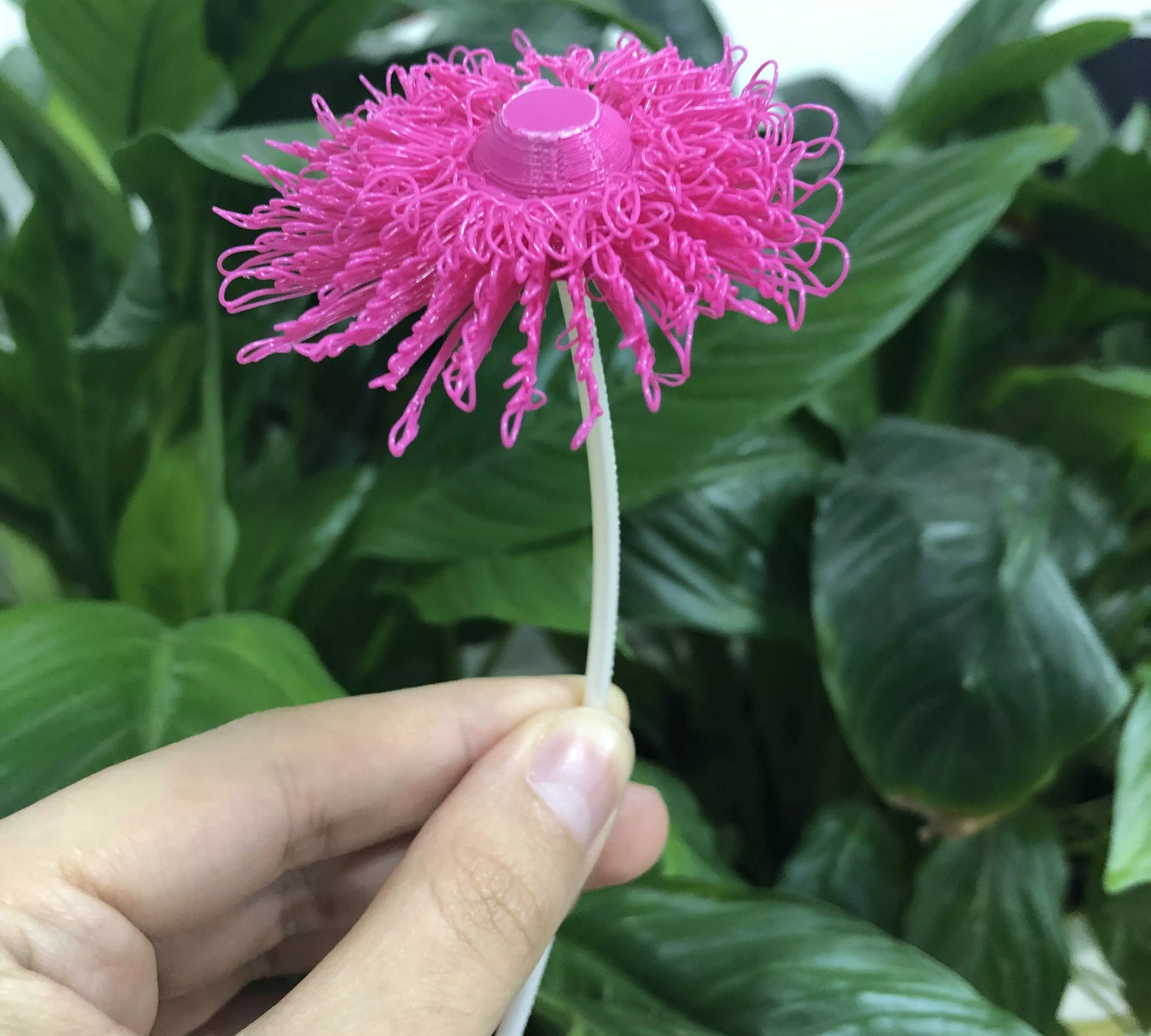
For this week's assignment I made a 3D printed flower using the flow/drooploop method, this allowed the flower to look more organic and natural. I love the effect of this printing technique becuase it is not reflected in the way you actually design your model but rather in the way your model is printed, at first glance when you look at the 3D model only it may not even look like a flower but when printed it looks like almost like a real flower.
The programs I used:
Fusion360 (3D Design)
Cura (Printing/Slicing)
3D Systems Sense (Scanning Software)
The hardware I used:
Handheld Sense 3D Scanner (GEN 1)
Ultimaker 3 Extended (3D printer)
This is my 3D Model of the flower that I created using Fusion 360.
Why is the project NOT made by subtractively?
My project relies on the 3D printer to be able to create the organic looking drooploop effect to get the curly petals. Also because my project has a center that uses the Revolve command and each petal was made as an individual object then combined each petal to the center which is revolved, also during the 3D printing proceess you must flip the design to get the drooploop effect so gravity will pull down on each layer to make it look curly, this look cannot be created with CNC machine. This project is best made using a 3D printer which is an additive manufacturing tool.
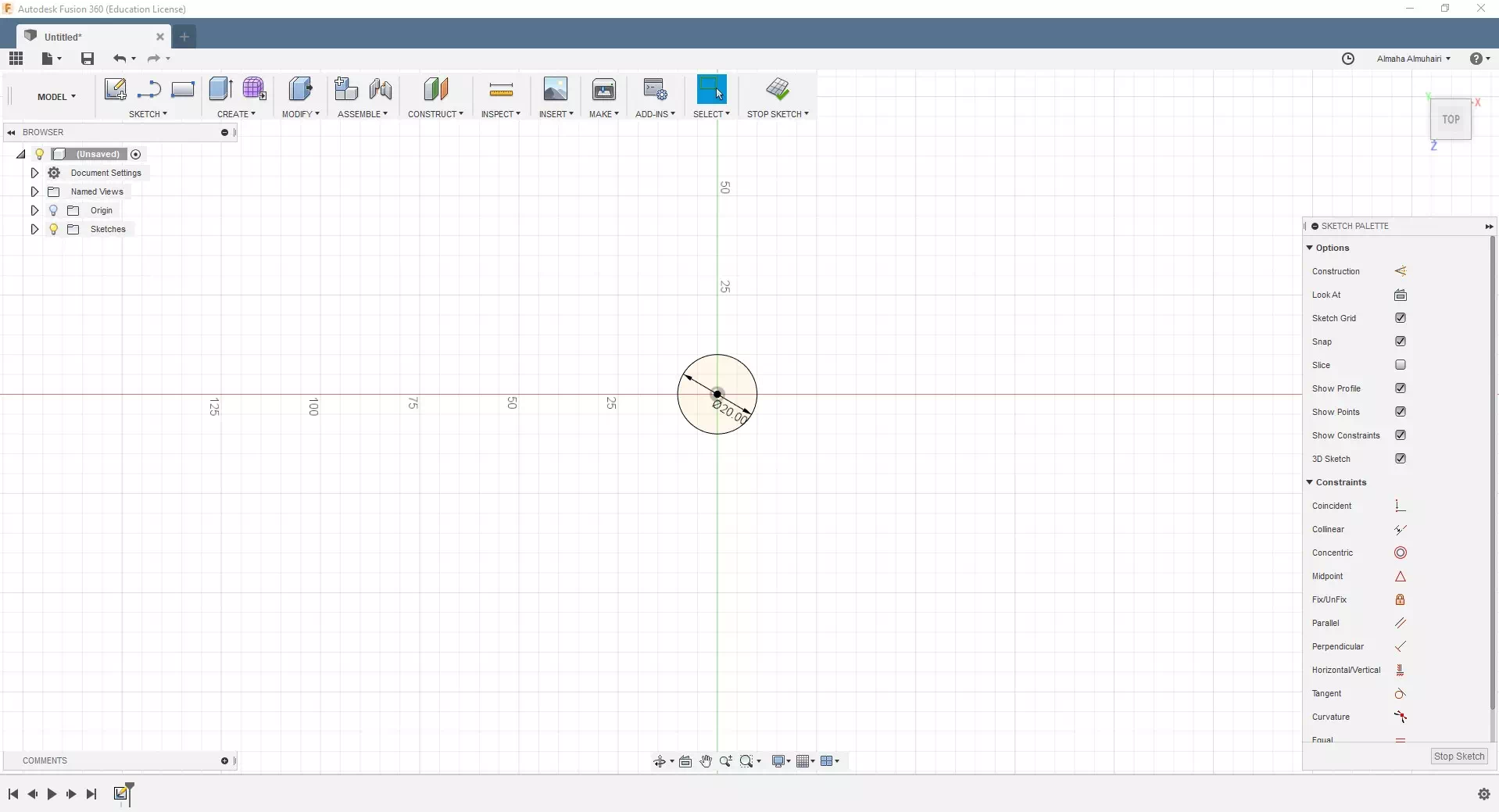
Start by creating a sketch. Use the center point circle to create a 20mm circle.
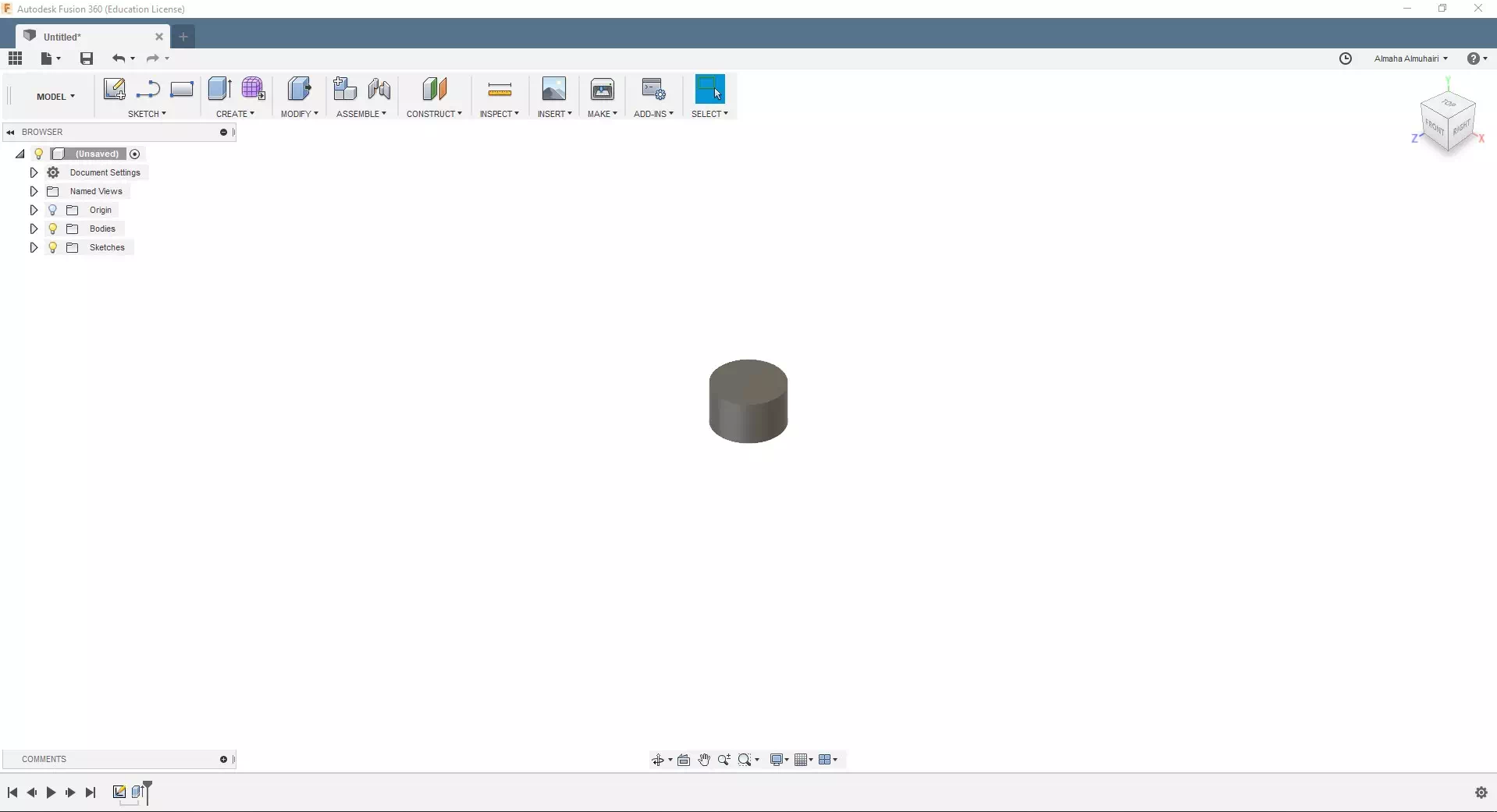
Extrude your circle using the E key on your keybaord, extrude up to 12mm.
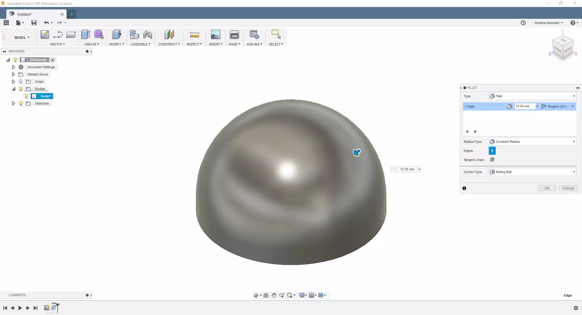
Add a fillet to the top edge of the circle, using the F key on your keyboard, input the following fillet options, 10mm on the top edge.
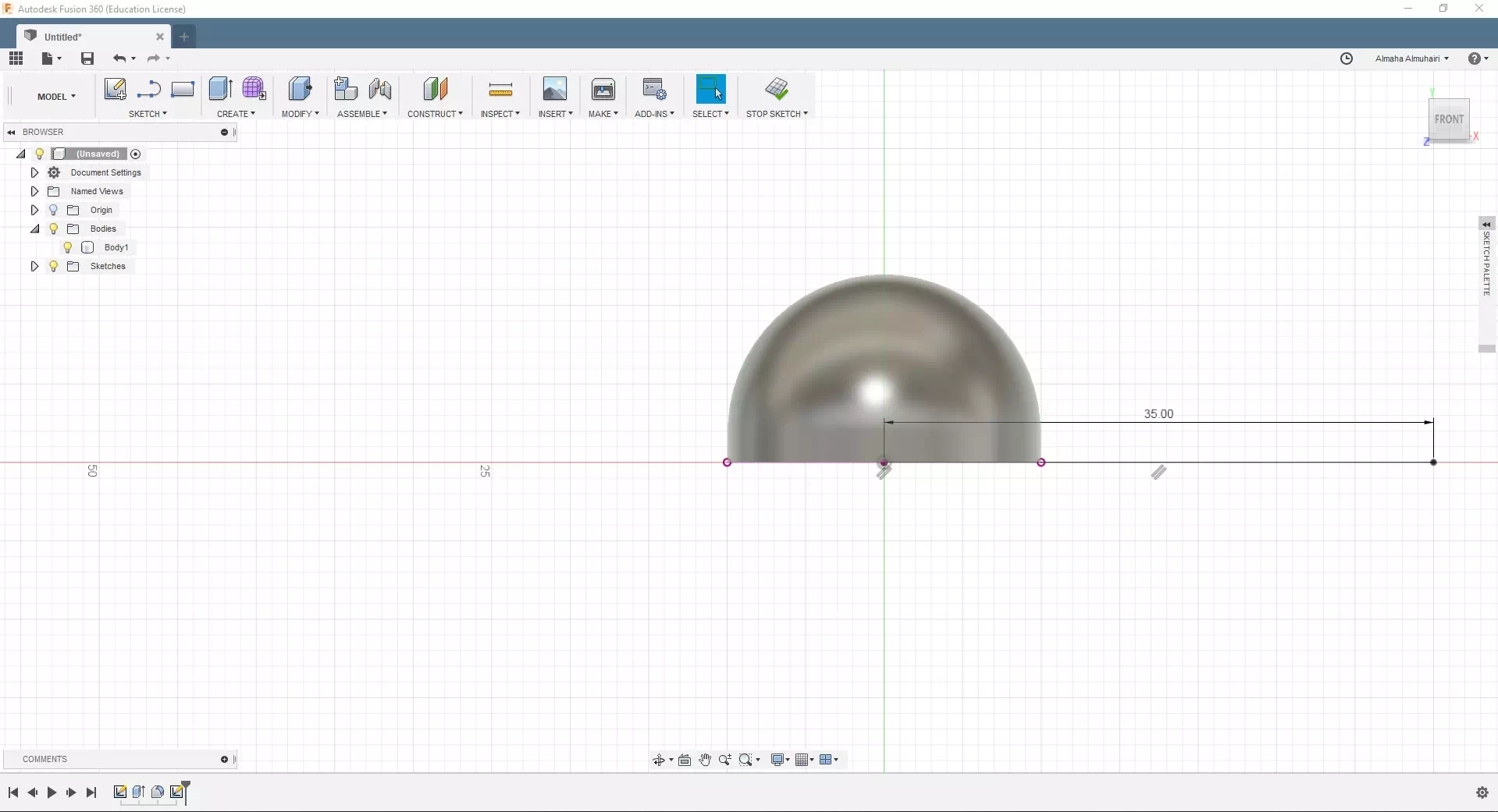
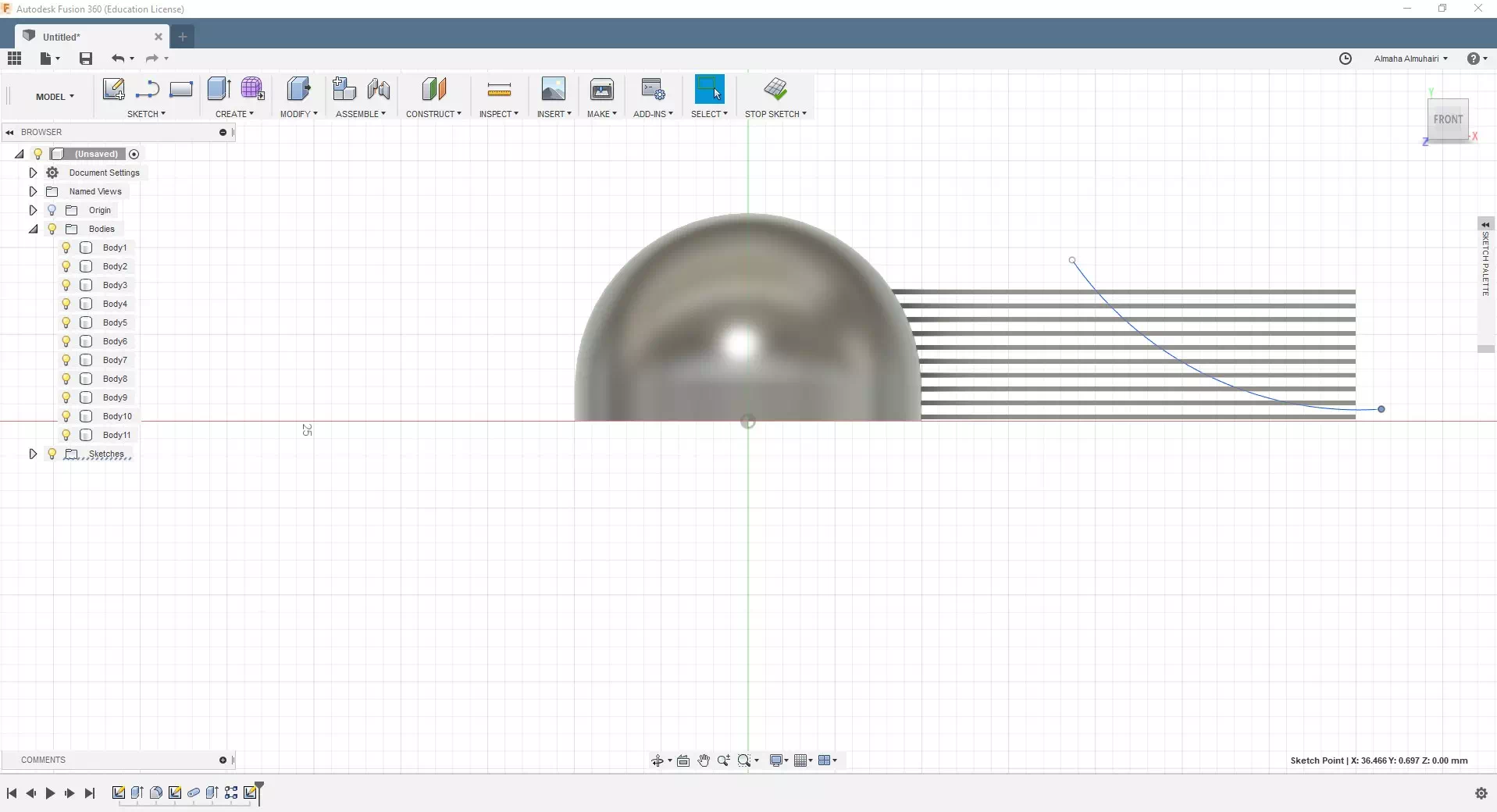
Let's create a line (from sketch mode) from the center out right X plane, give the line a distance of 35mm.
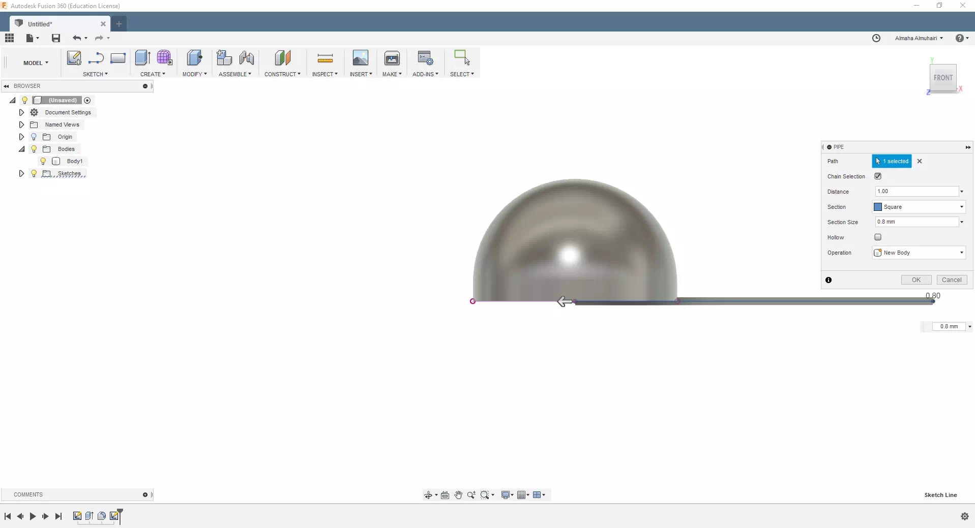
Using that line, we will now create a pipe using the pipe tool in the create tab, select the line, in the distance set it as 1.00, for section set it as Square, for Section size set it at: 0.8mm, the operation should be new body.
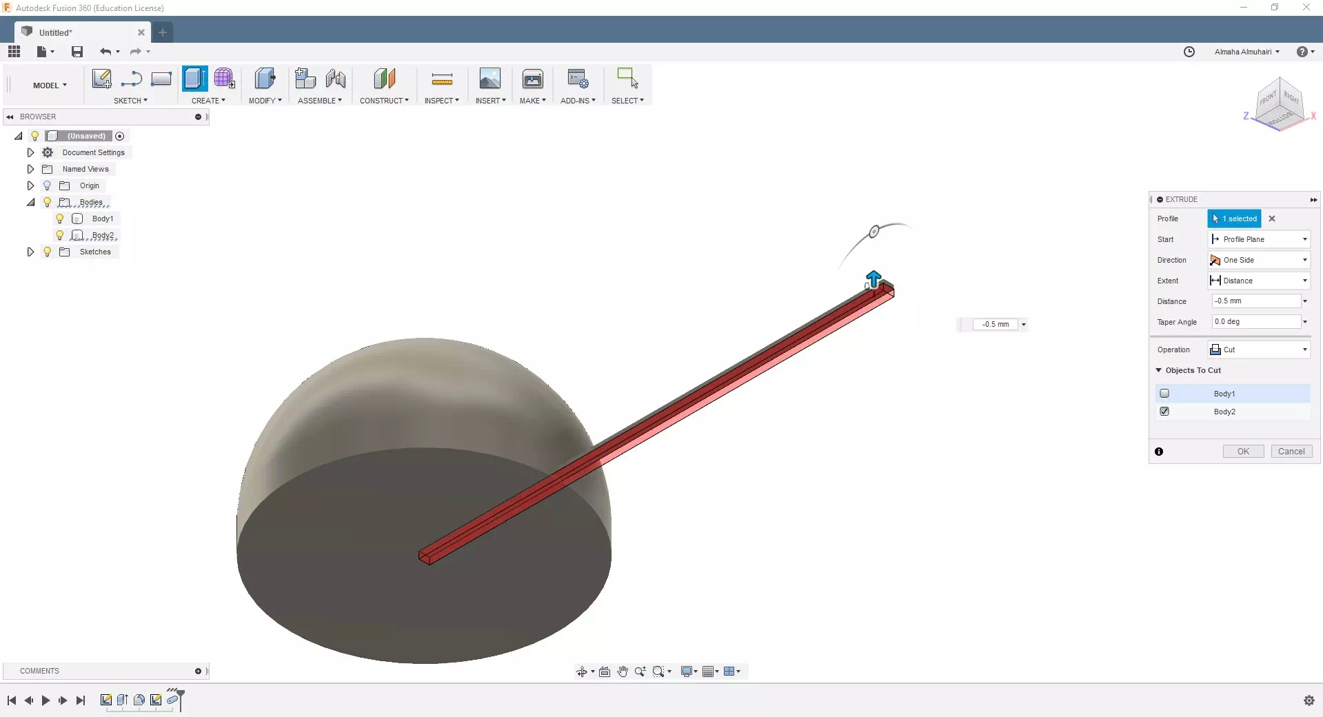
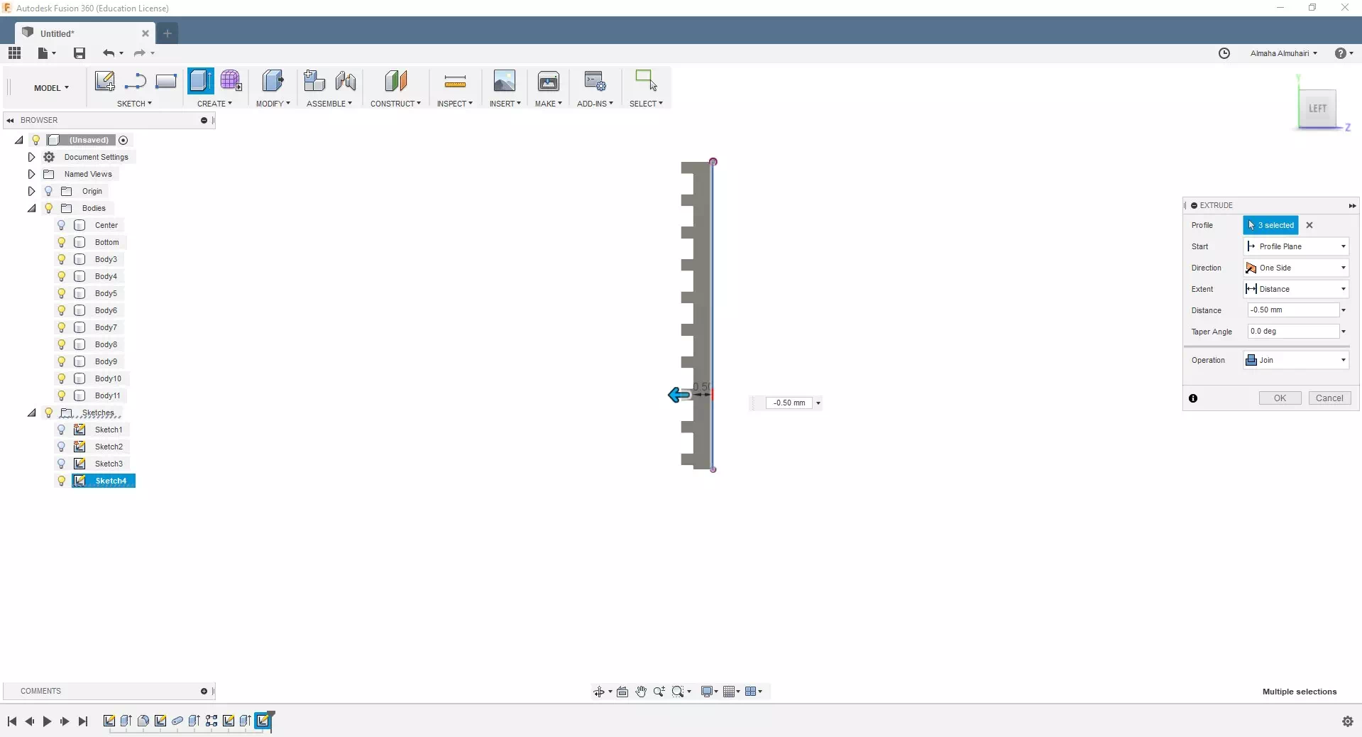
Select the newly extruded pipe frome the bottom, then extrude it in the cut opeation, extrude the pipe to a distance of -0.5mm, when asked objects to cut deselect body 1.
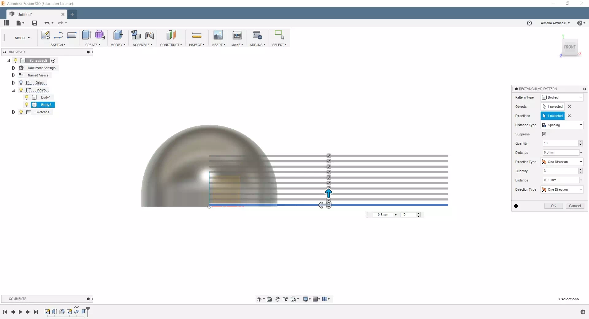
Select this pipe, under the create tab, create a rectangular pattern, for direction select the Y axis, direction type: spacing, quantity: 10, distance: 0.8. These are now our "petals"
To add a layered edge to these petals we must create a sketch, make a three point arc; make sure this arc holds all the petals but not the bottom petal/line.
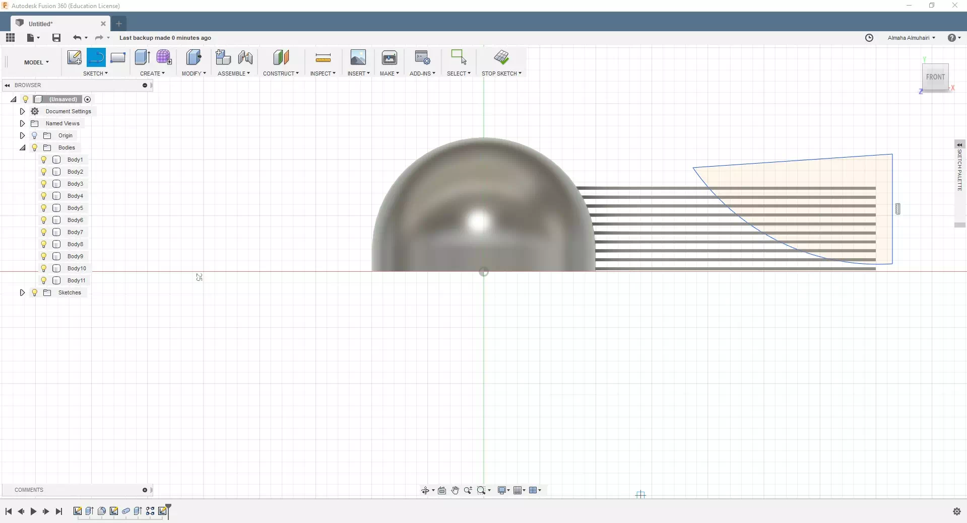
After creating your arc, just connect the rest of the arc using lines by clicking the L key on your keyboard.
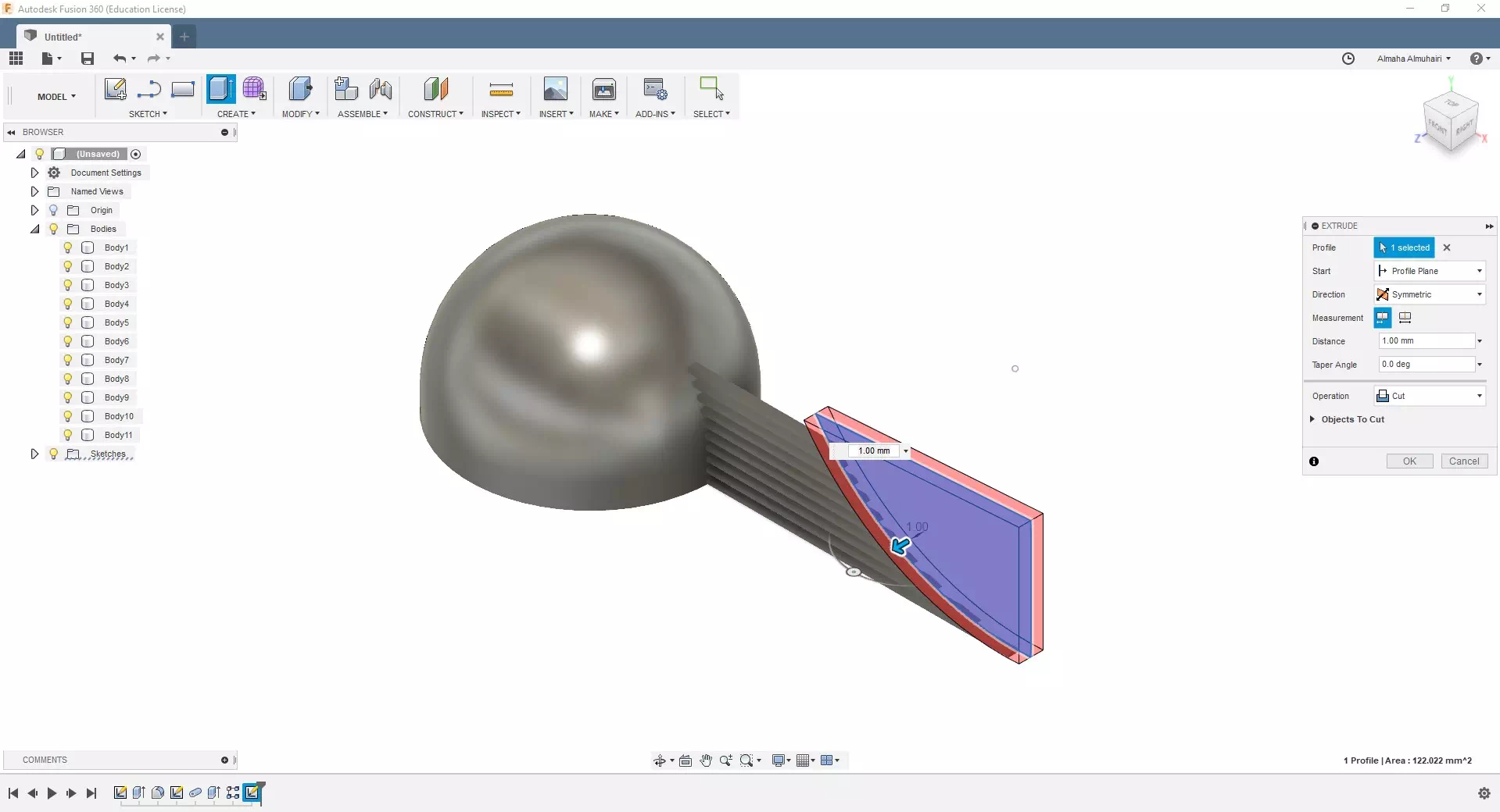
Select your arc, extrude it on Symmetric directions out just to cut all the new lines, set the operation to cut.
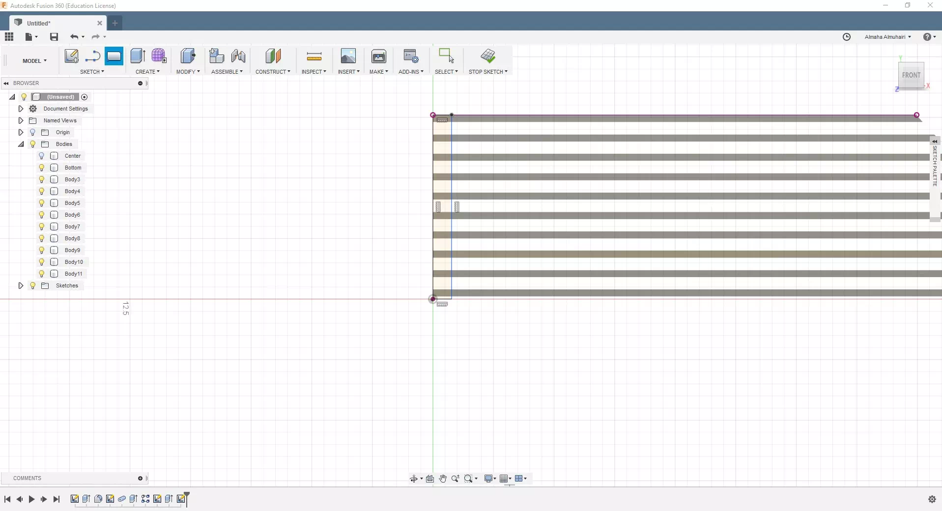
We have a lot of petals so we should try to join them, let's create a sketch of a rectangle that touches all the ends of the petals.
Extrude the sketched rectangle, just enough to touch the bottom of all petals and set the operation to join.
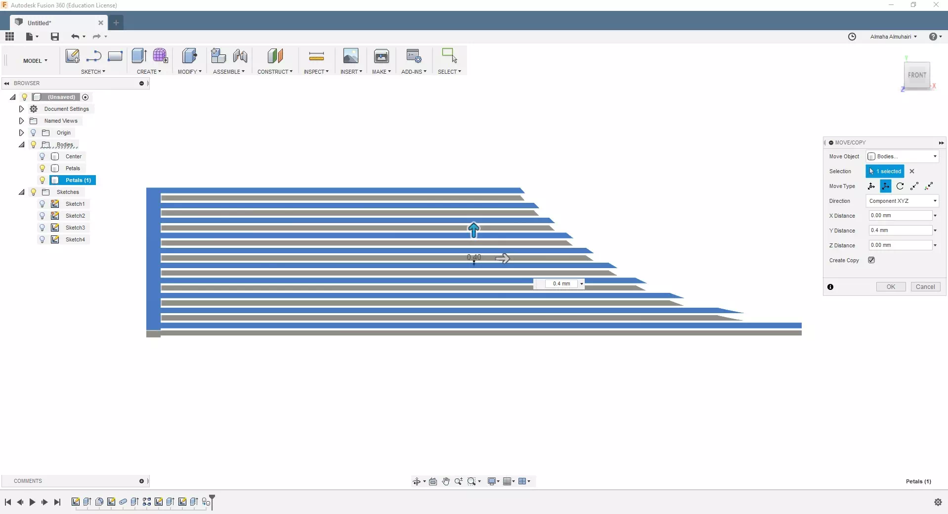
Right click the newly joined petal body to click the move/copy command, check the create copy box, the move type to translate and the Y distance to 0.4mm.
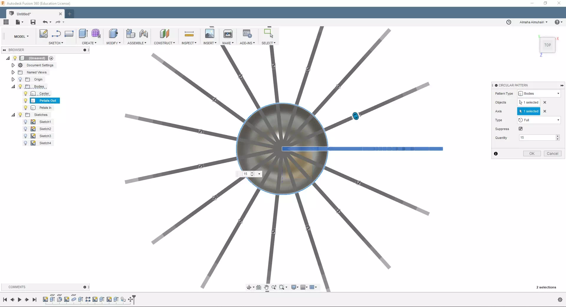
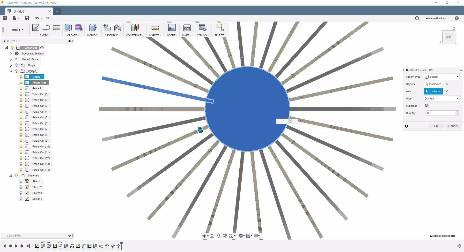
Now that we have our petals done we should surround the rest of the flower with them. Under the create tab; lets create a circular pattern, select the original petals we had created (the one before the previous step) and for axis select the edge of the circle for quantity: 15.
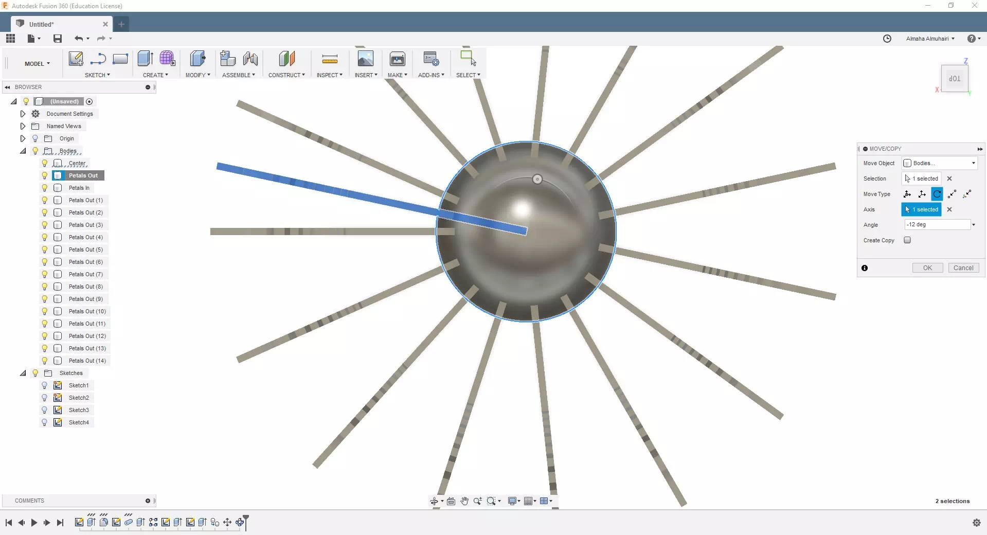
Select the second set of petals, right click to the move/copy command. For move type select Rotate for axis: -12 deg
Now create a circular pattern like the previous steps of these petals, with the same quantity of 15.
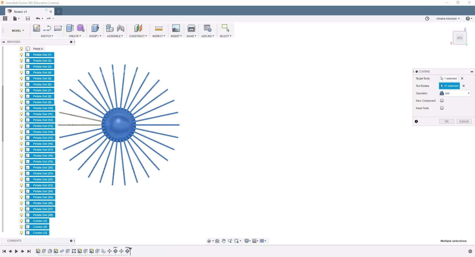
As you can see we have many bodies, lets join them all into one body. on the Modify tab click on the Combine command choose the center as the target body, the tool bodies will all the rest of the bodies you sould select from the browser by highlighting then selecting the Join operation.
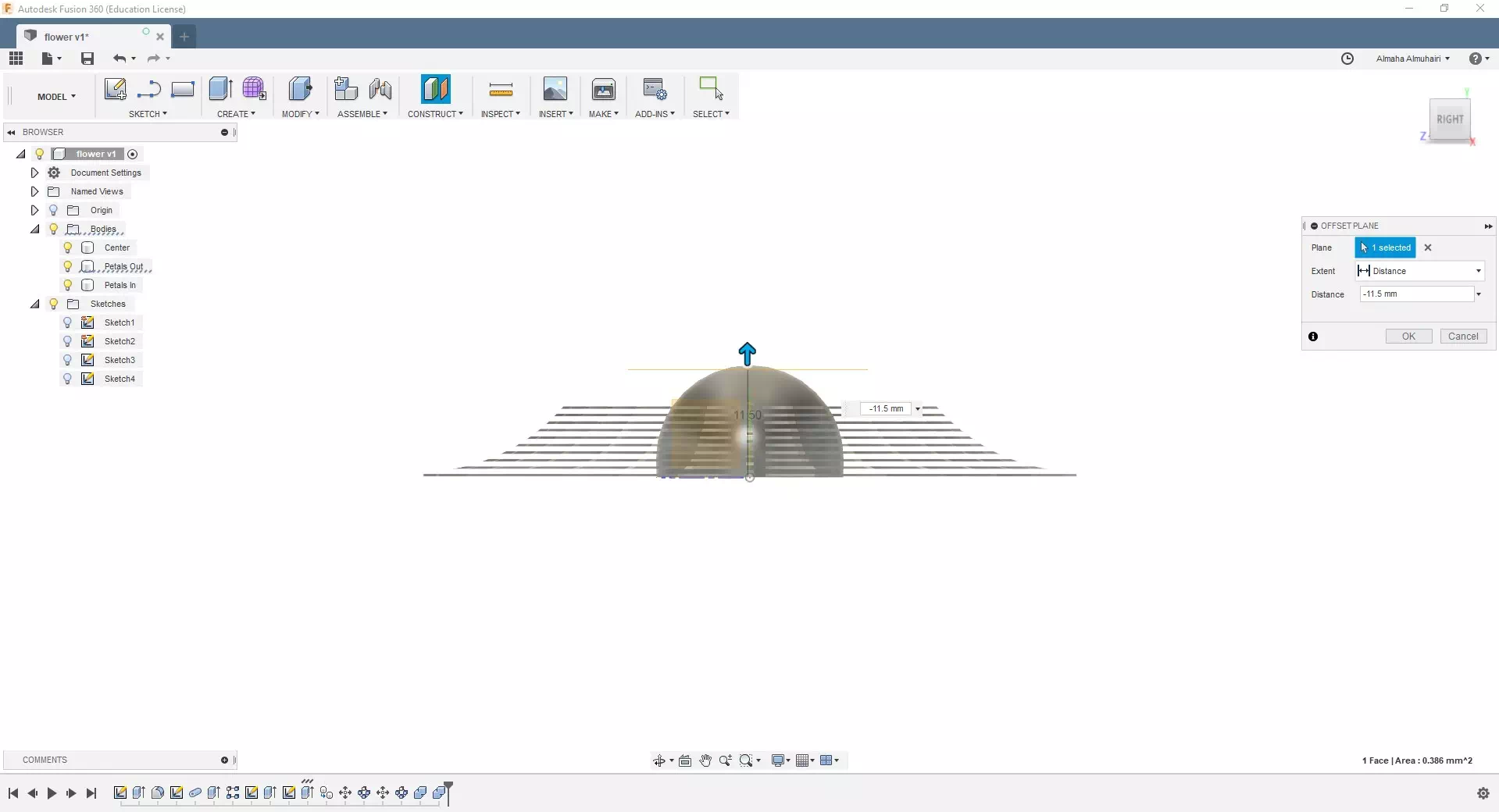
Since we are printing the flower upside down we need to flatten the top, in the construct tab and create offset plane on the base bottom, the distance is -11.5. Then go to the modify tab click on split body choose the main body then splitting tool click the new plane we just created, then right click the new body in the browser to remove it.
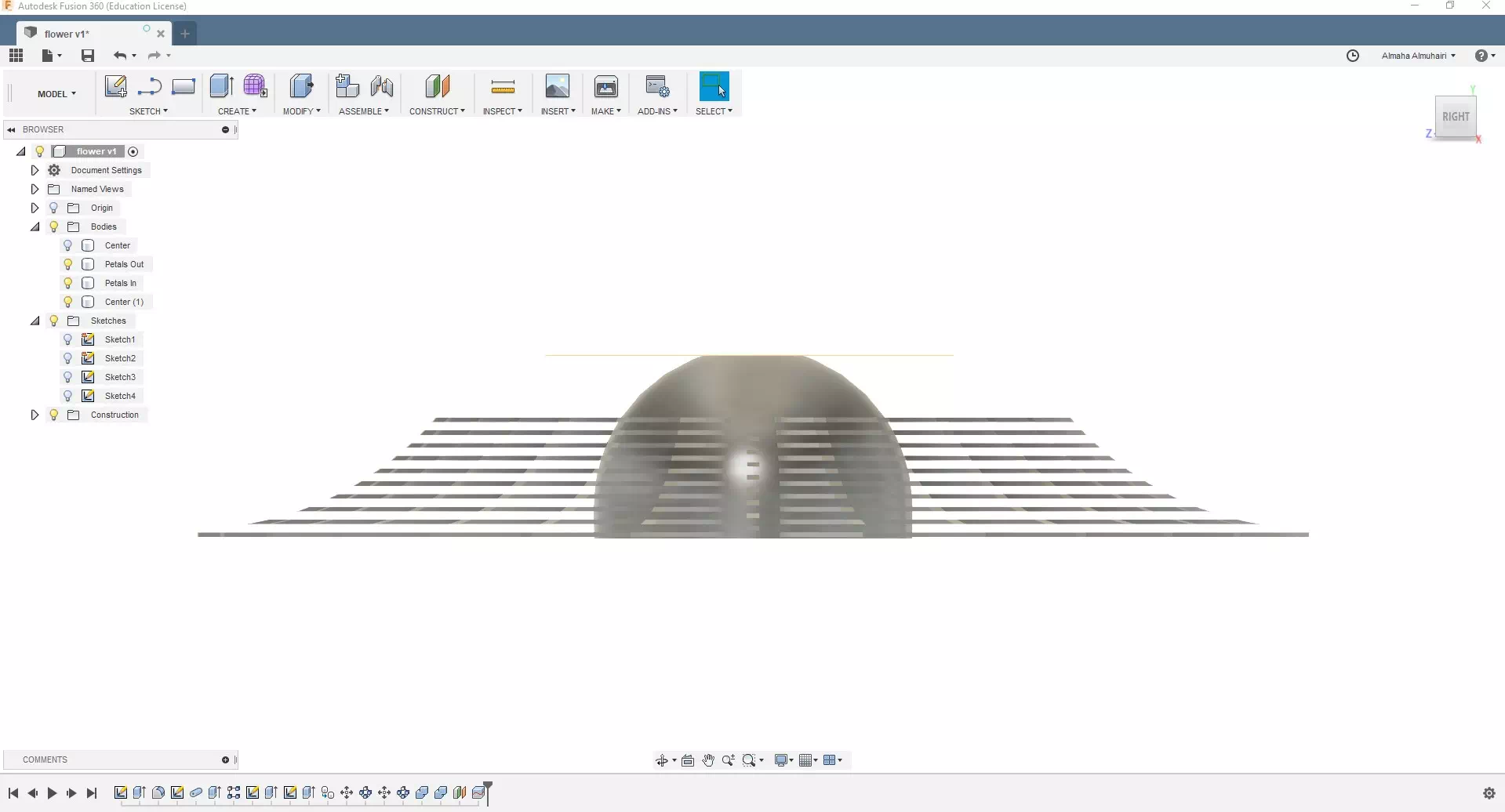
The result should look like this.
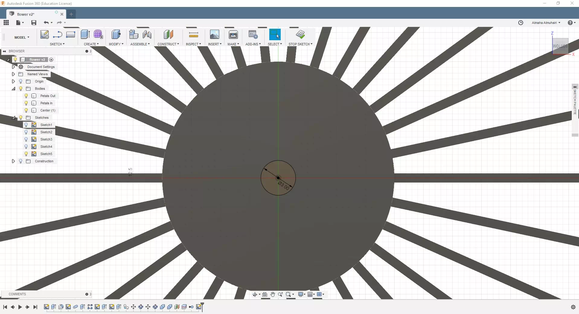
On the bottom of the center, create a sketch of a center point circle. This will allow us to add any peice of 3mm fillament to use a stem for our flower. The distance should be 3mm.
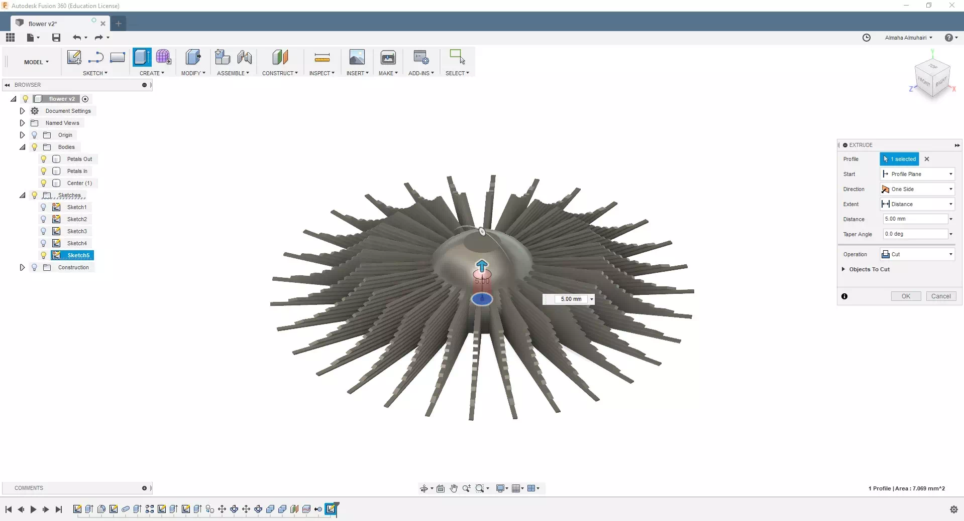
Extrude the circle into the center by using the Cut operation by a distance of 5mm.
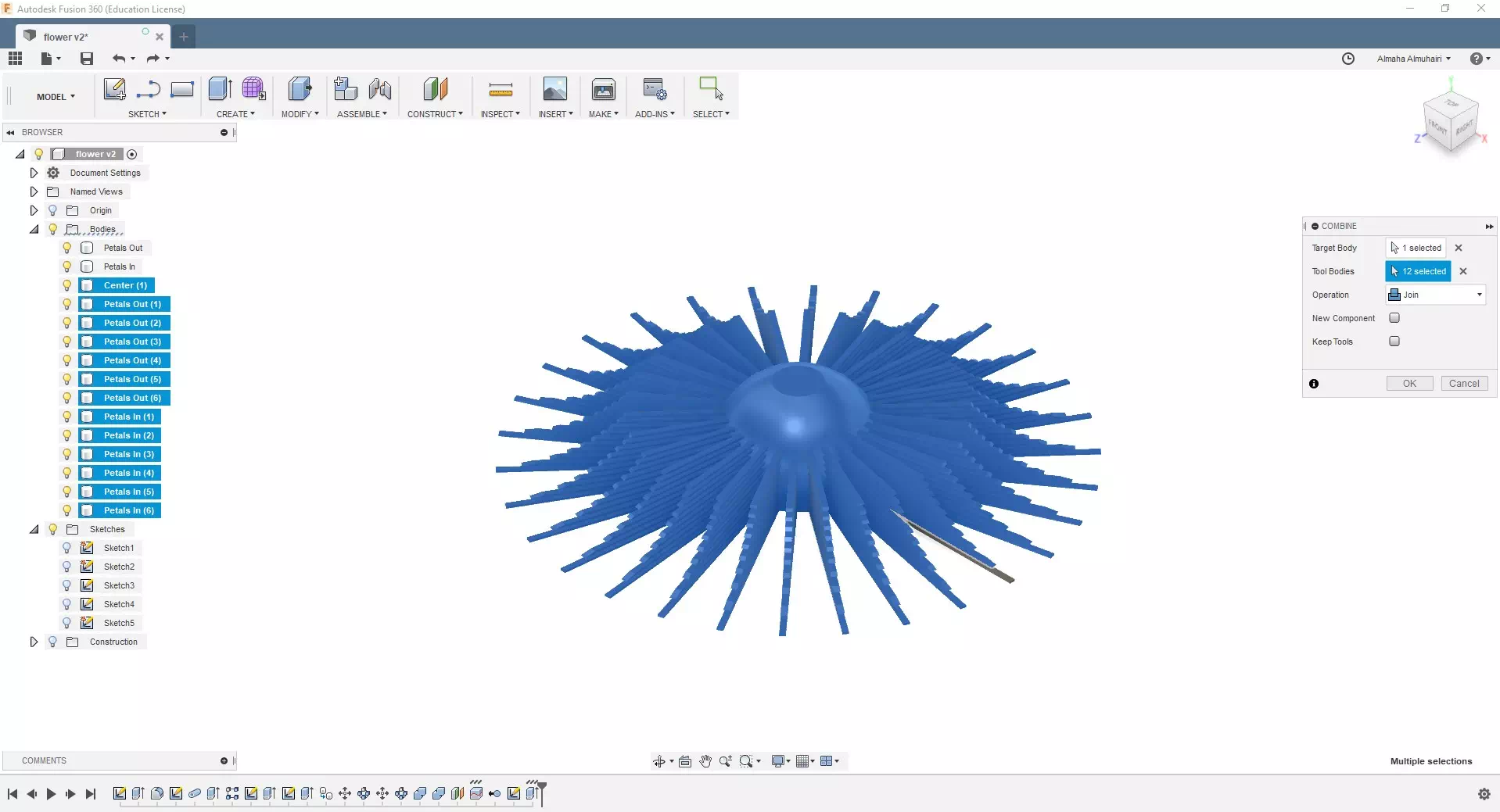
This is the last step.As you can see we have many bodies again, lets join them all into one body. on the Modify tab click on the Combine command choose the center as the target body, the tool bodies will all the rest of the bodies you sould select from the browser by highlighting then selecting the Join operation.
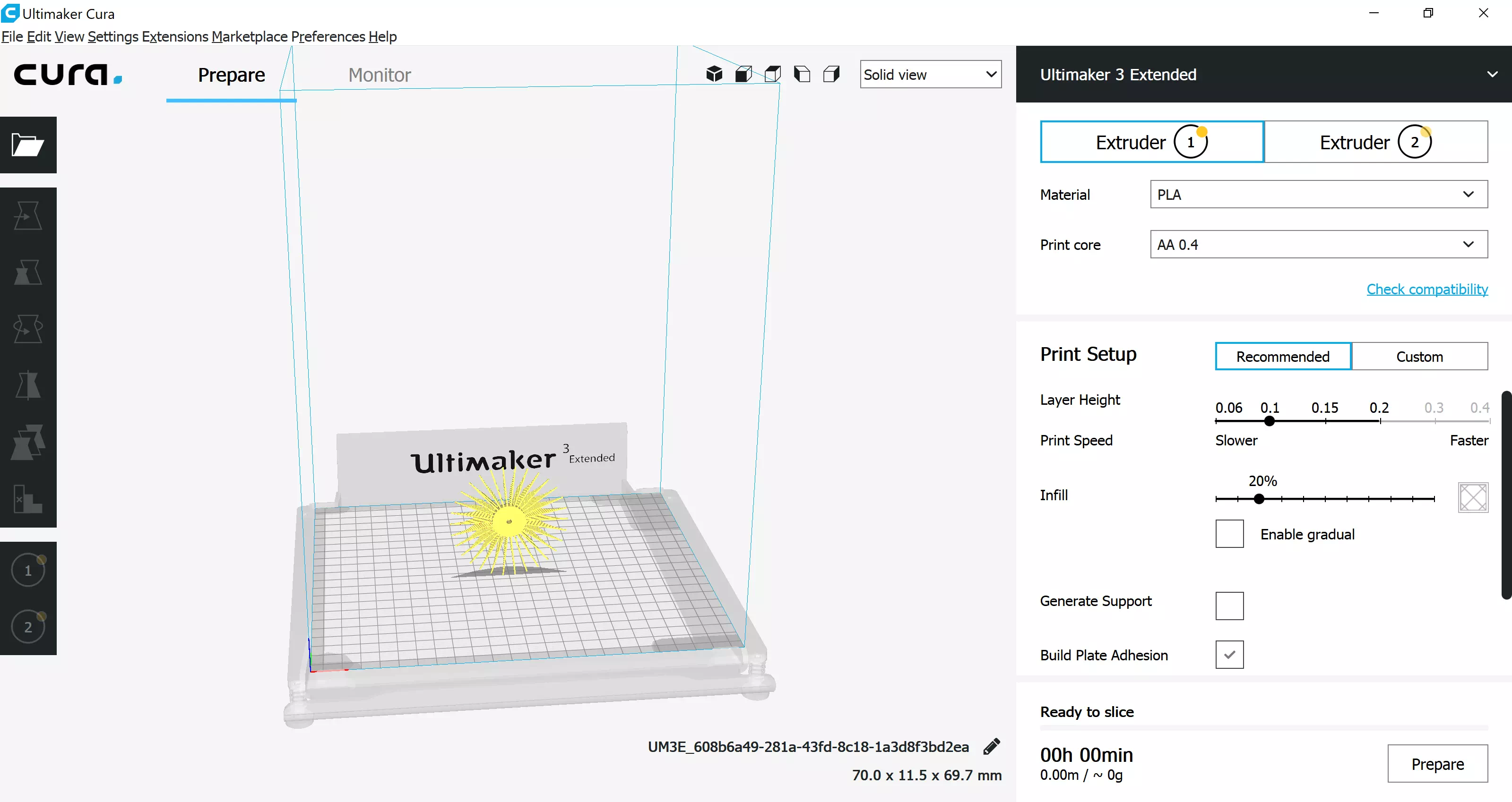
Open Cura and and open your files.
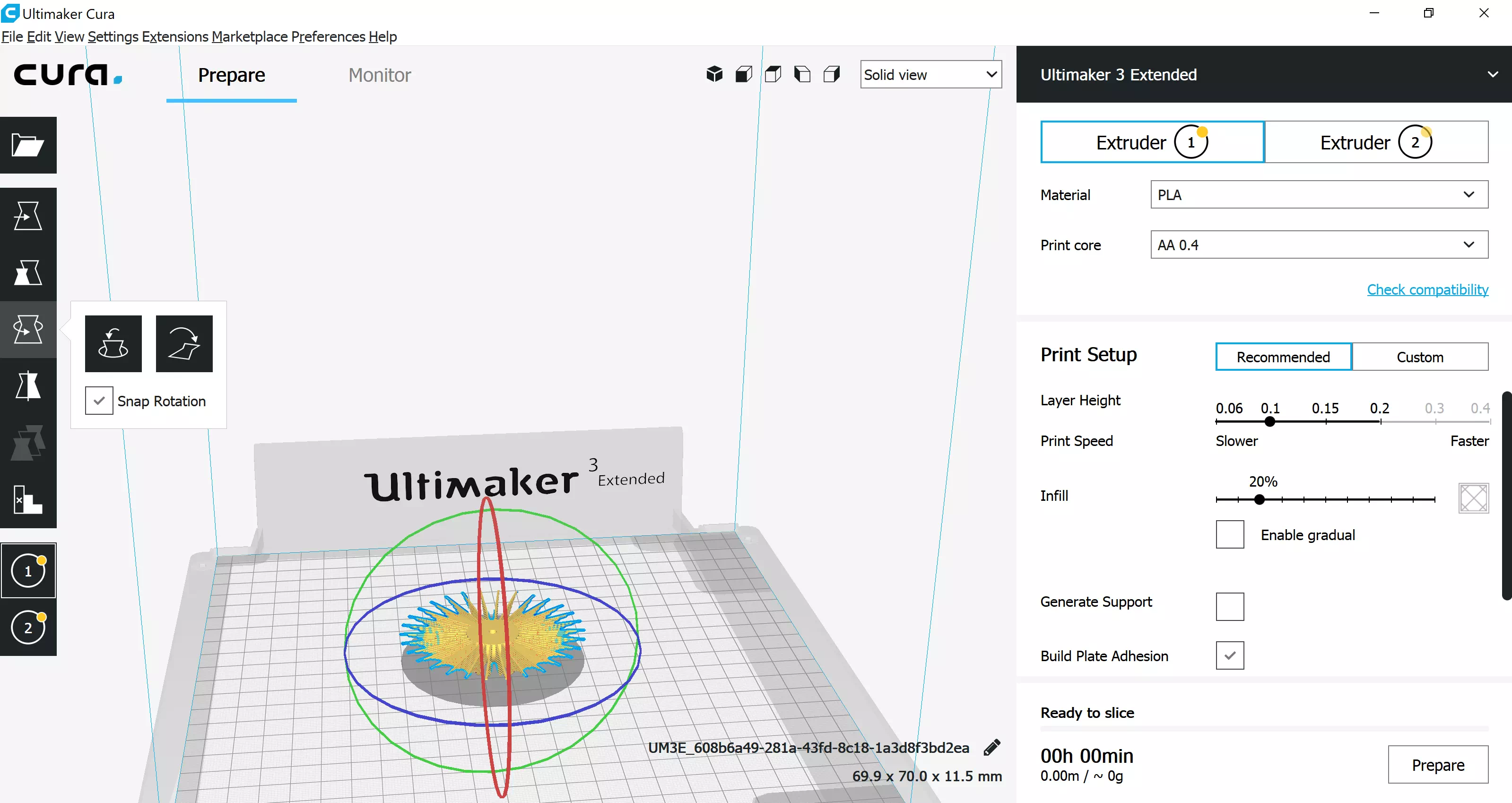
Rotate the flower and lay it flat upside down.
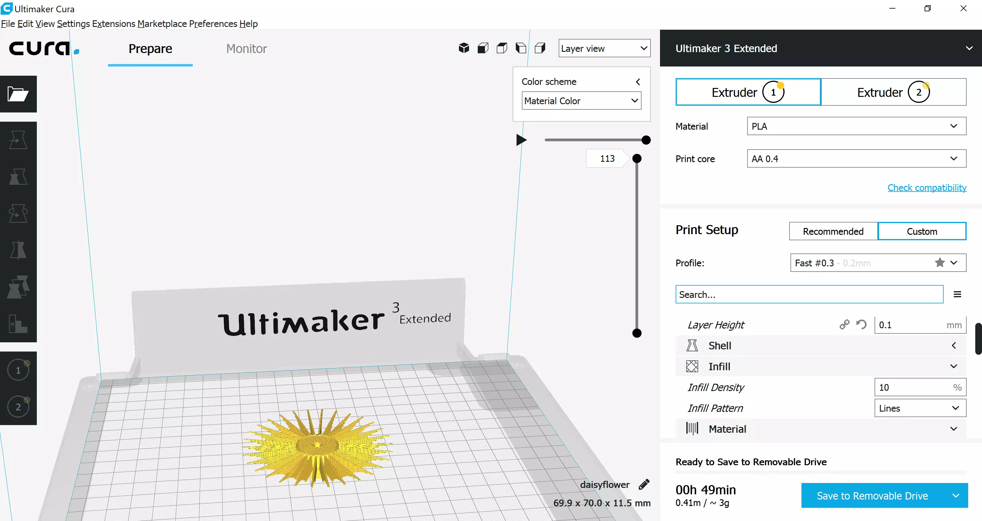
Change the infill to 0.3 or 0.1.
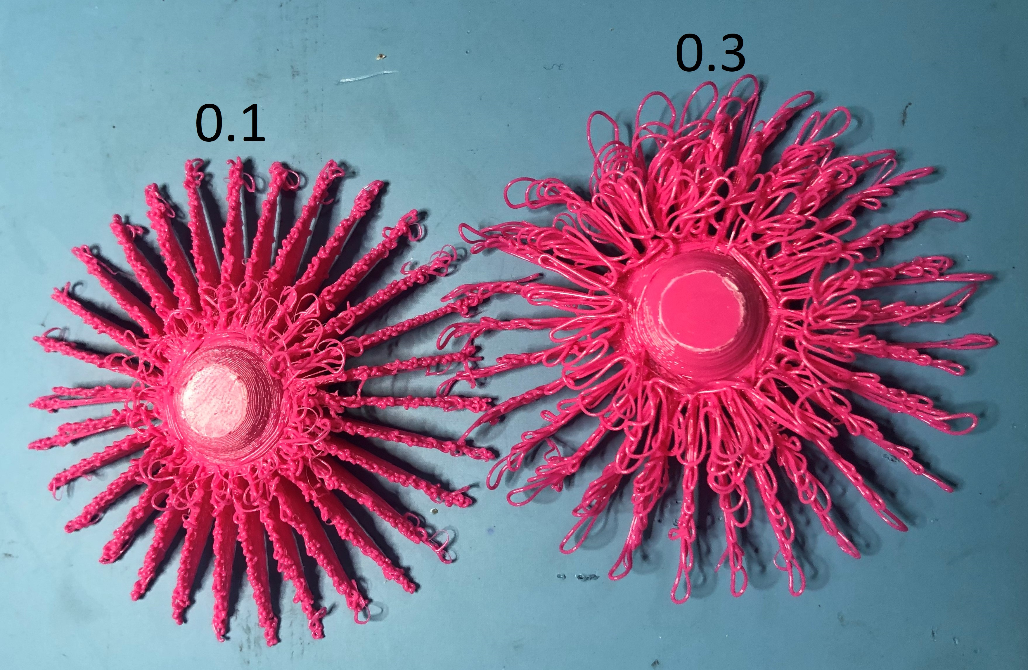
As you can see the difference between the two different types of prints, I prefer the texture of the 0.3 flower it looks much more curly.
Attach a used fillament to the hole below the flower to act as the stem of the flower.

Open the 3D Systems Sense software, then select object.
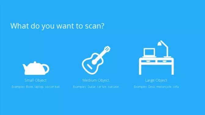
Select small object.
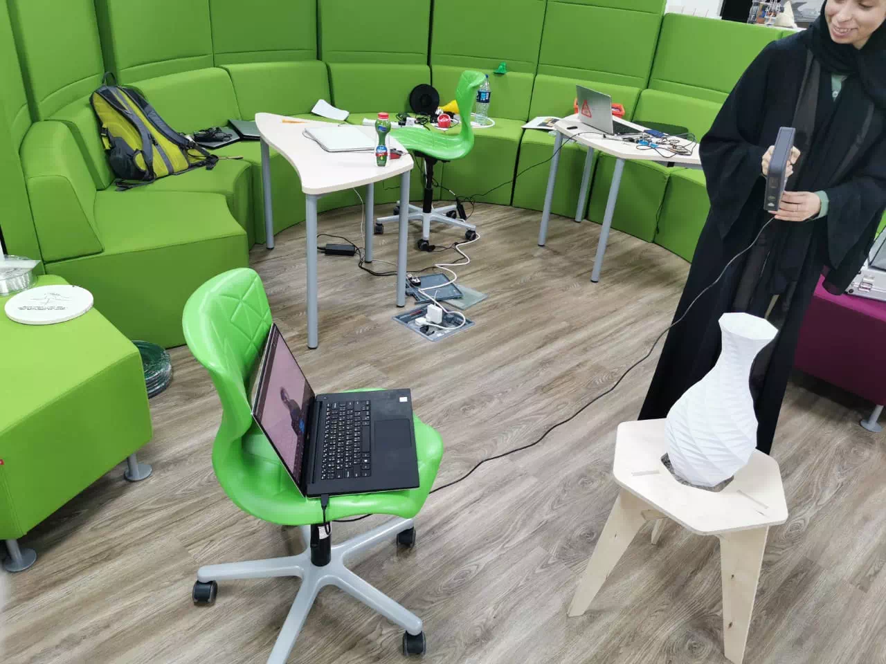
Place your object on a stool and begin scanning, do not move the object, just go arrount the object very slowly till you make a full 360 turn around your object (Tip: place the scanning laptop on a rolling chair so that you can move your scanner freely without any tangled wires). My object is a 3D printed vase made by my mentors (Daniele Ingrassia and Hashim Al Sakkaf) using thier BigFDM Machine.
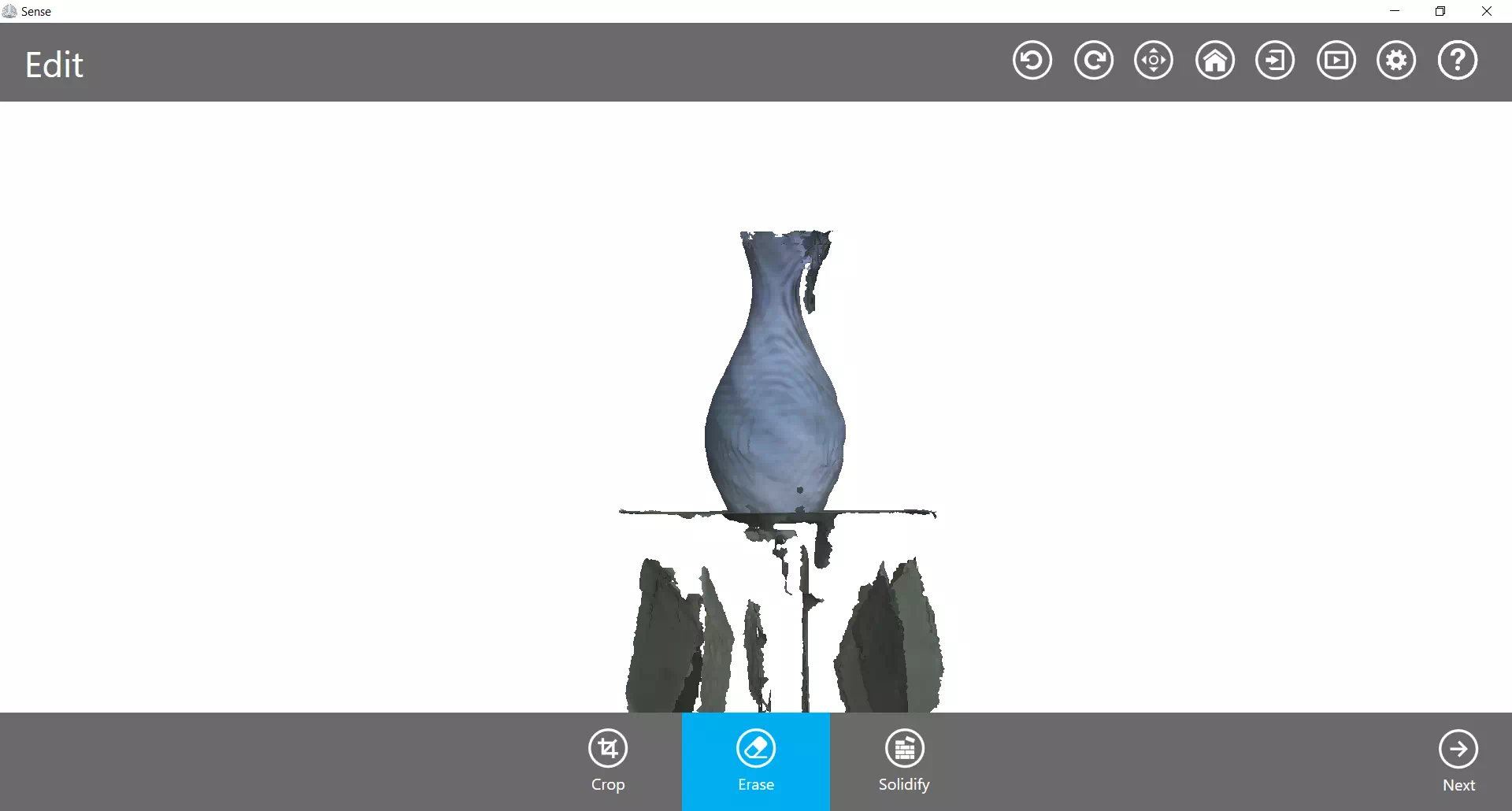
After scanning the vase, you will get a messy scan like this.
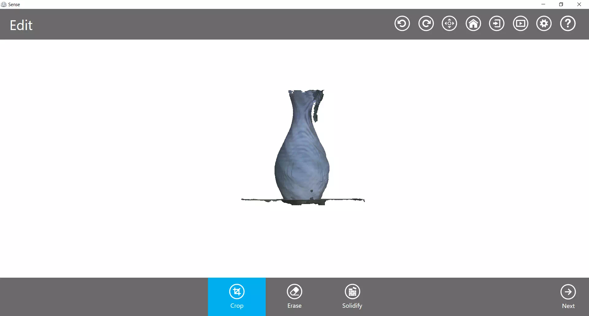
We need to clean the scan, start by cropping the table.
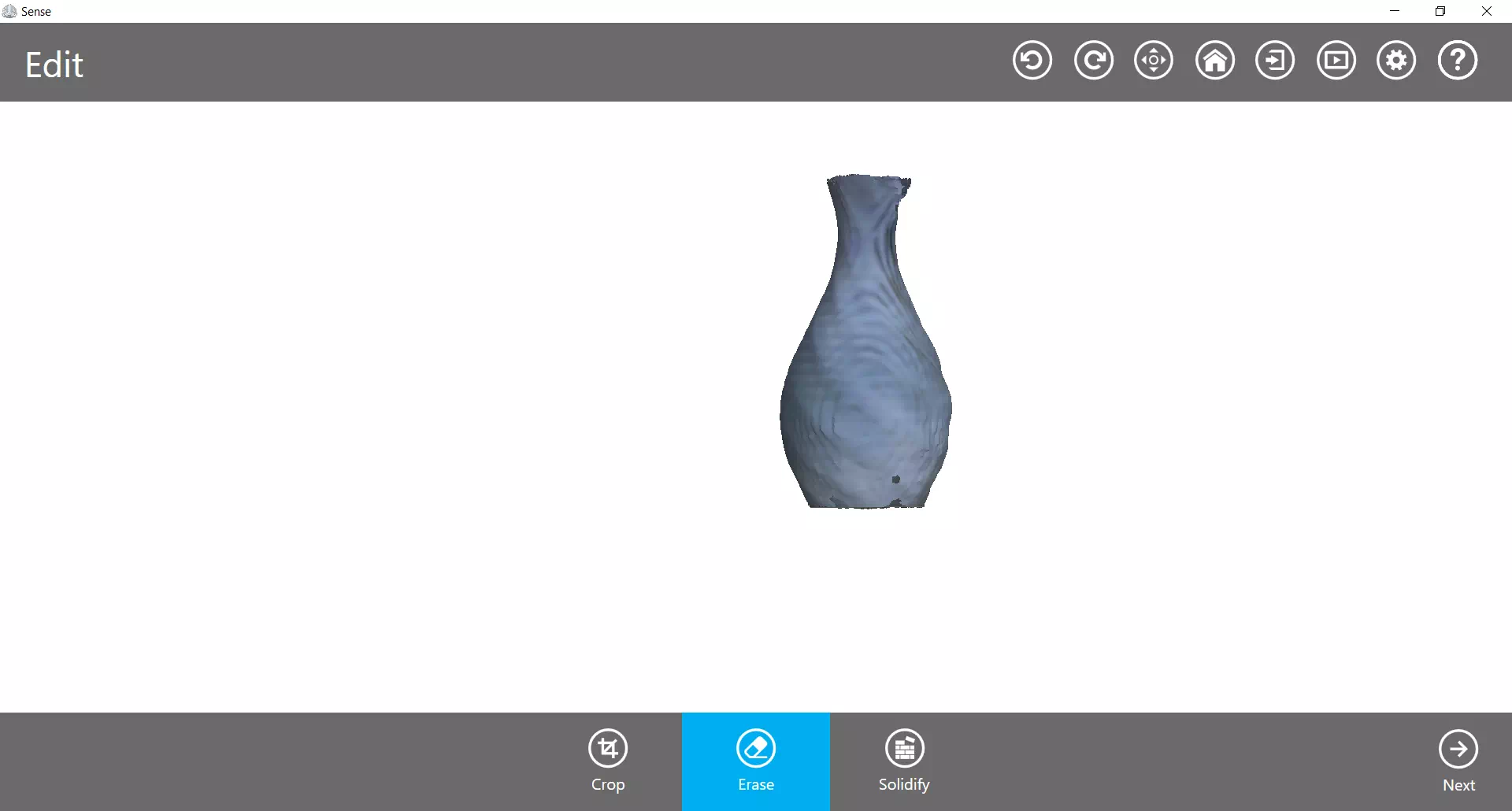
Then using the erase tool clean the edges.
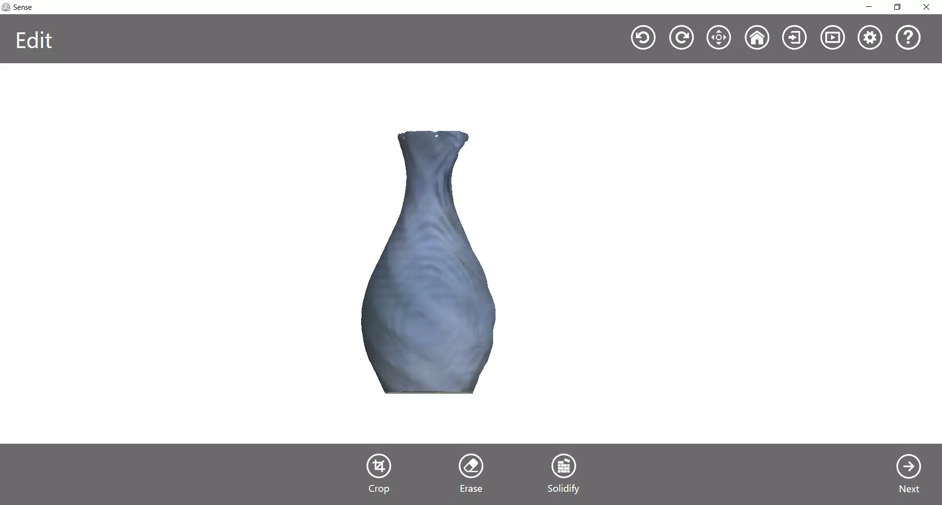
Then using the solidify tool, make it in into a solid.
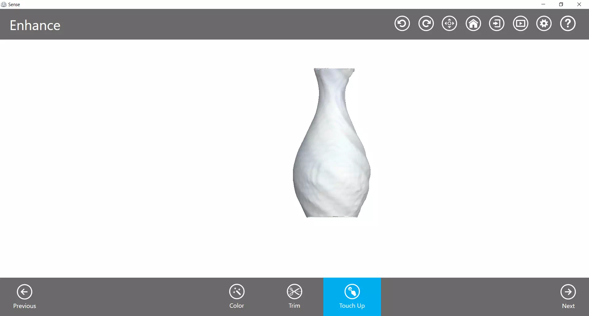
Then using the touch uo tool fix the hole on the top of the vase and smooth out the rough surface.
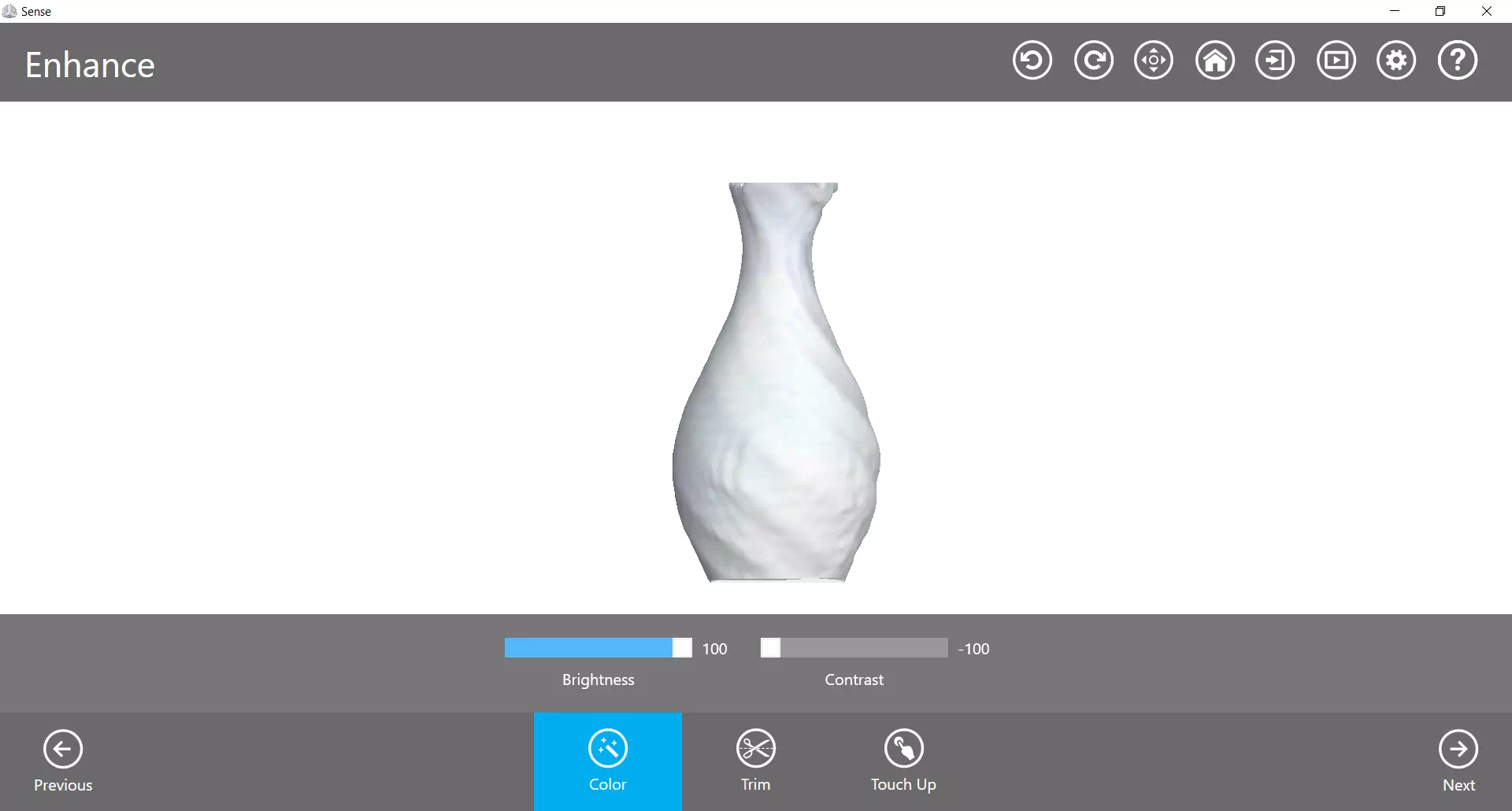
The last step is to change the color of the vase, by adjusting the brightness and contrast to make the vase white, after that click the Next to save your scan as a OBJ file, you can download my Vase Scan Here.