Week 5
Feb 13. Electronics Production
Group Assignment
Characterize the design rules for your PCB production process. Our equipment is a Roland MIll MDX-20.
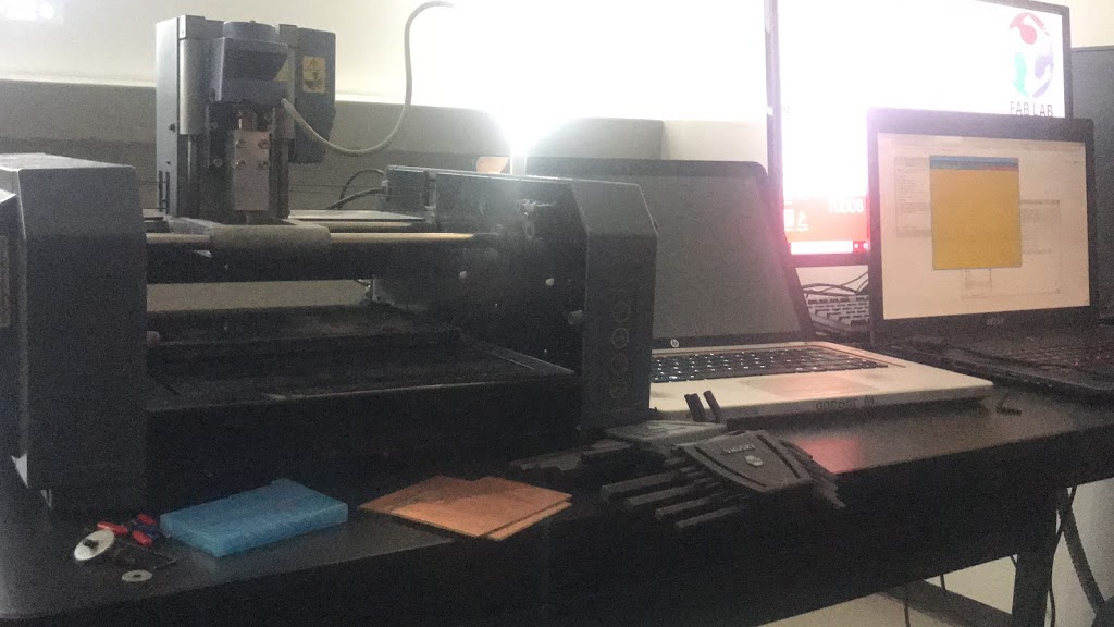
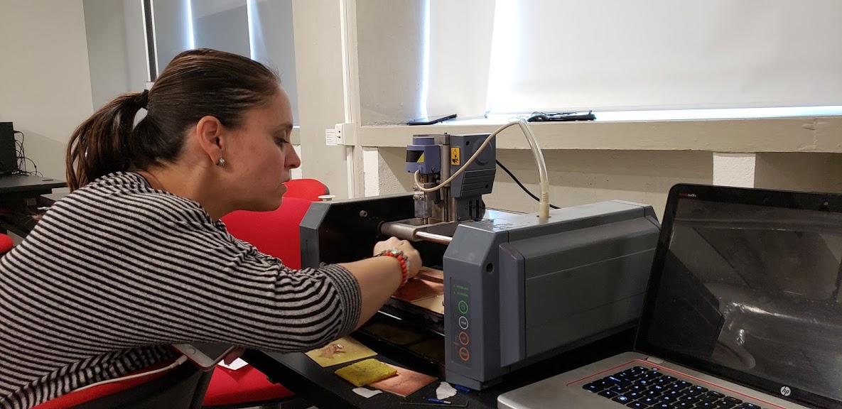
Roland Mill MDX-20
Our PCB making equipment is a Roland Mill MDX-20.
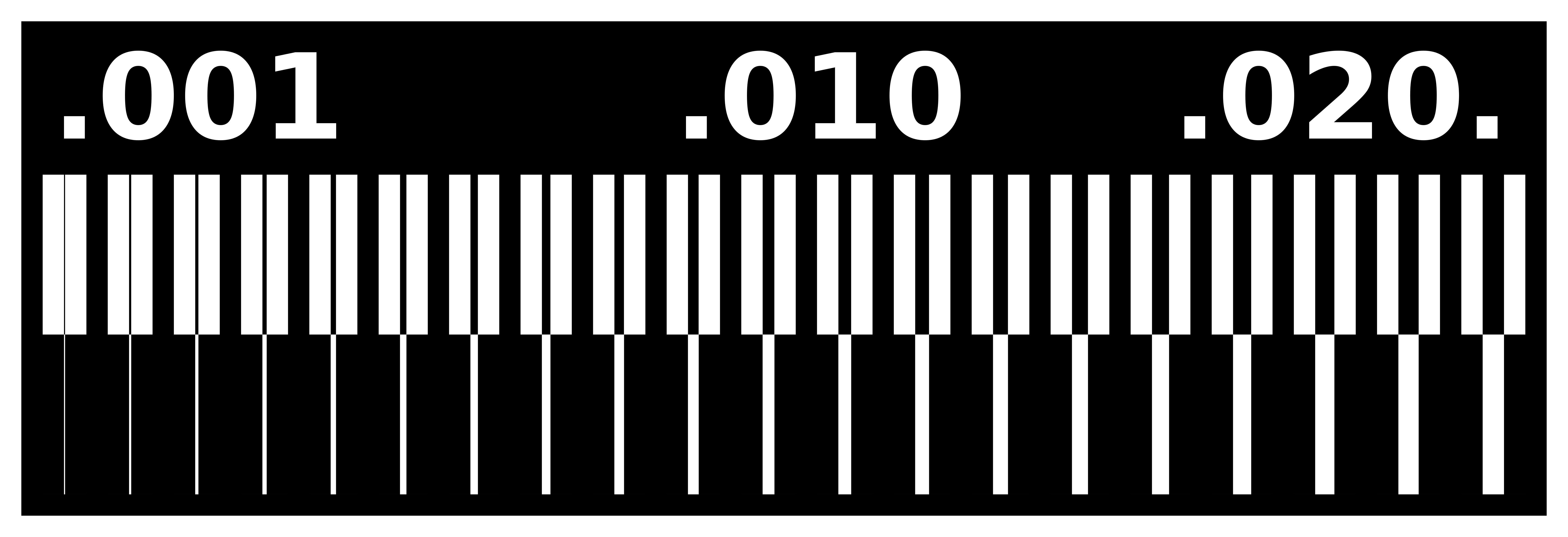
PNG for Group Test
The PNG for the test engraving is sused to create the final model in FabModules.
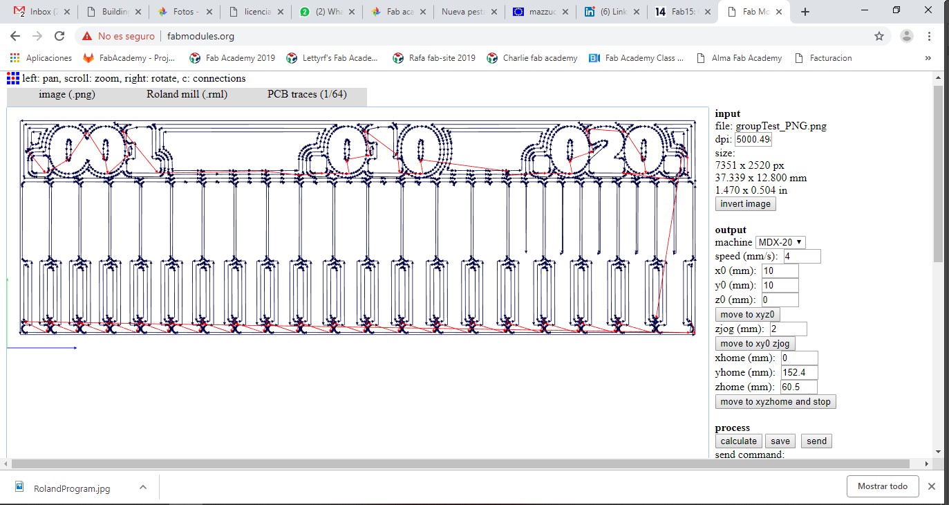
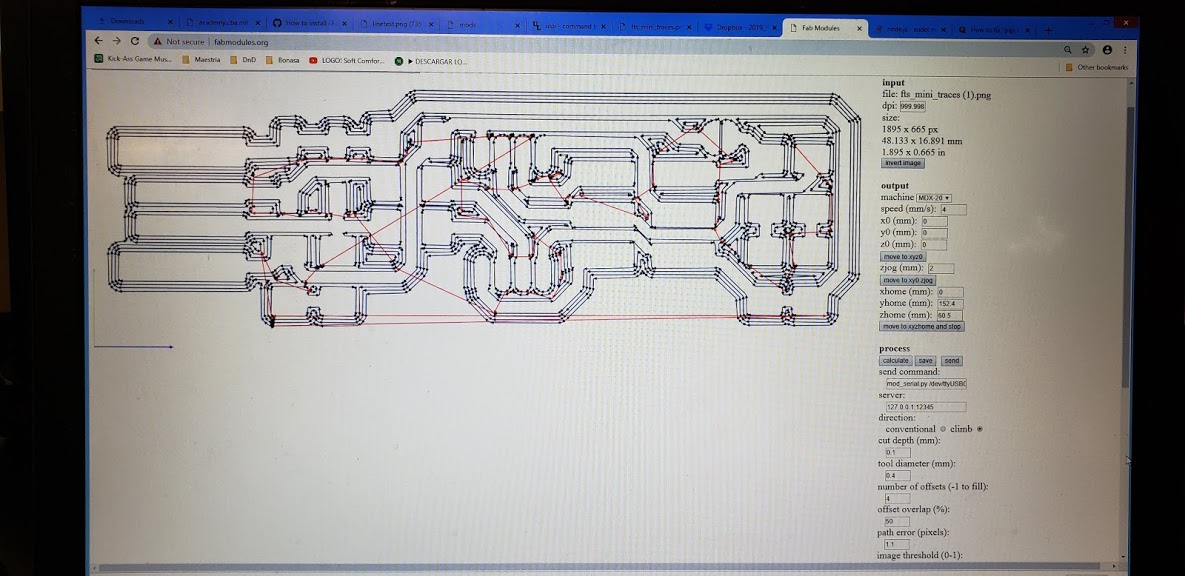
Line Interpretation from FabModules
Line interpretation from FabModules of group test.
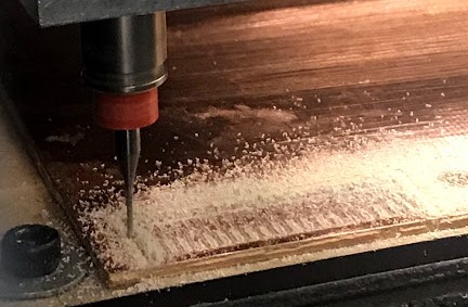
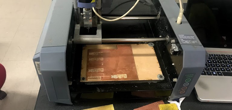
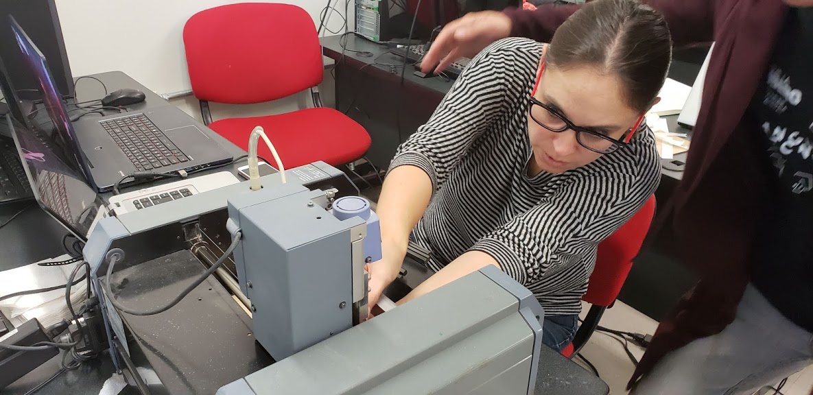
Engraving
The Roland Mill engraved perfectly.
Review Engraving
We reviewed how it engraved and sanded it before attempting a cut.
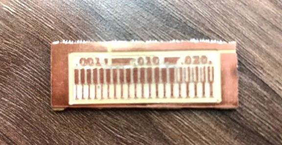
Final Group Piece
Final group piece. Our equipment has a problem to cut all the way through, so we cutted it by hand. It's being repaired now hopefully it will be fully usable by the time the next electronics practice comes around.
Instructions
- Download images for inner (engrave) and outer lines (cut)
- Put a sacrifice bed on the Roland Mill
- Attach with double sided tape your material
- Open Fab Modules
- Start configuring to engrave the test
- Input format: PNG
- Output format: Roland Mill
- Process: PCB traces 1/64
- Define the dpi and size for the image
- Define the correct coordinates for the material to be engraved, in this case every time it was 0,0,0 because the coordinates were given by the Roland Mills Software.
- Define the zjog (space neede to change points within engraving):2 mm
- Define number of offsets, we decided to go with 4 as a standard for all engravings
- Define the tool diamater used: 4 mm
- Define Offset Overlap: 50%
- Define cut depth for engraving: 1 mm
- Calculate to obtain the final image in lines showing each offset
- Save as an .rml file to be used in the Roalnd Mill Software
- Open the SimpleFAB-20-RolandMDX software
- Define the coordenates within the yellow canvas in the Software
- Upload the .rml file
- Press Start
- Enjoy the engraving process
- The correct steps after engraving are: change the engraving tool for the cutting tool, configure in Fab Modules the outer lines for cutting, this is achieved by changing the cut depth to go all the way through the material (6mm), calculate and than process it on the software for the ROlan Miller. All of this was done several times, wihtout and than with the local isntructor to understand why it wasn't cutting, after five tries and several different problem solving approaching the ranged from debugging to yelling to the Roland (we are not proud and it obviously did not work). After the instructor did several different tests the disgnose was it's not going to cut in the near future we need to give it service.
- So we wouldn't get behind on assignments we decide to cut by hand.
- After cutting it you need to sand it so it will take away the excess material at the edges.
Individual Assignment
Description

PCB Lines
Brian's PCB creation.
FabModules Calculation of Lines
Fab Module's interpretation of Brian's PNG
Final Engraving
Final product of engraving.
Changing Tip
After engraving the tip must be changed to cut.
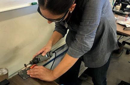
Finishing touches
Sand excess material with a dremel.
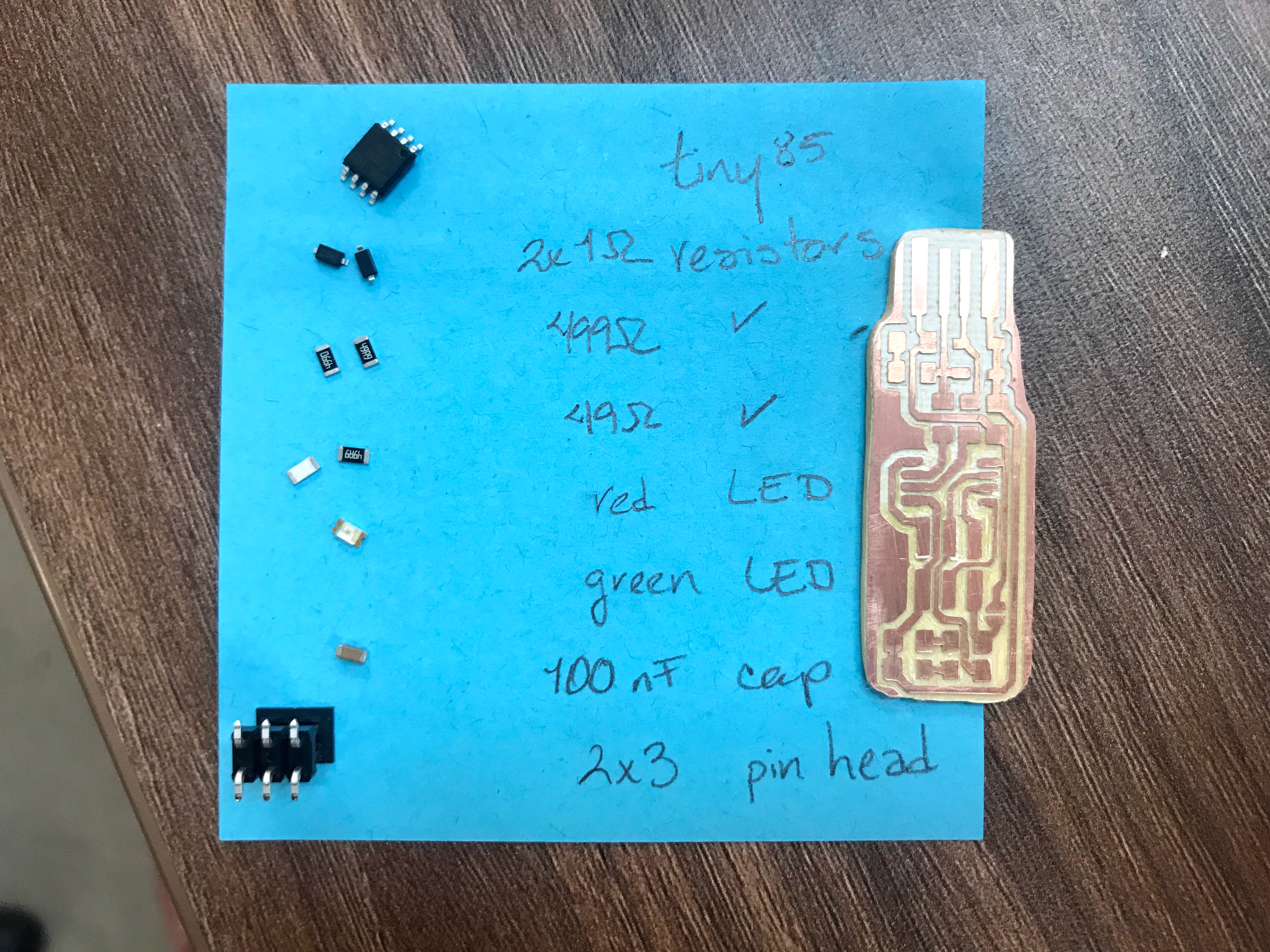
Most Pieces
Most pieces required next to the engraved PCB.
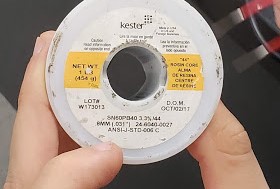
Soldering Material
Soldering material used through the process.
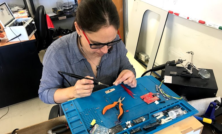
Soldering
A difficult first experience soldering electronic components.
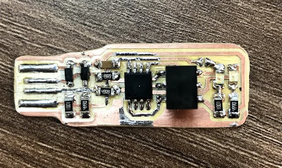
Final
All the components soldered into the PCB.
Cables into my PCB
Test to see if it works, I found out later I soldered two green LEDs.
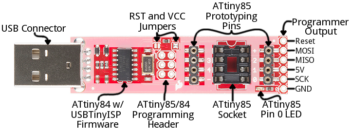
Hook Up GUide between PCBs
Hook Up Guide to program the PCB.
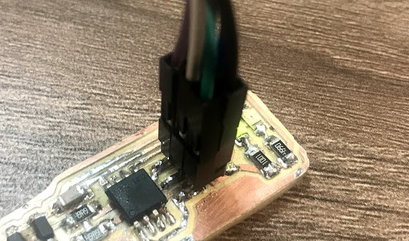
Origin for Cables
Cables connected to original tinyUSB PCB.
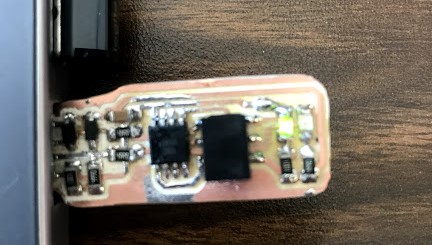
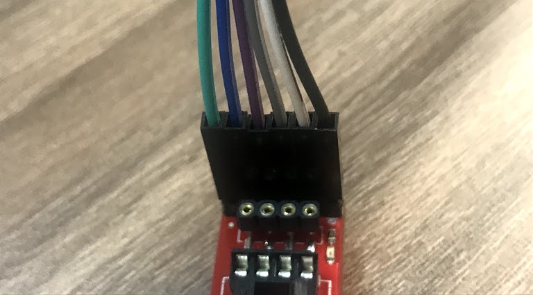
Cables into my PCB
Cables connected to my PCB.
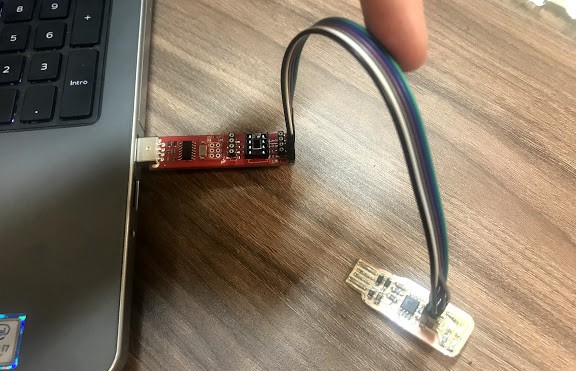
Connection between PCBs
Final connection between computer, original PCB and mine.
Burn PCB
Include the basic driver for the PCB to be programmed.
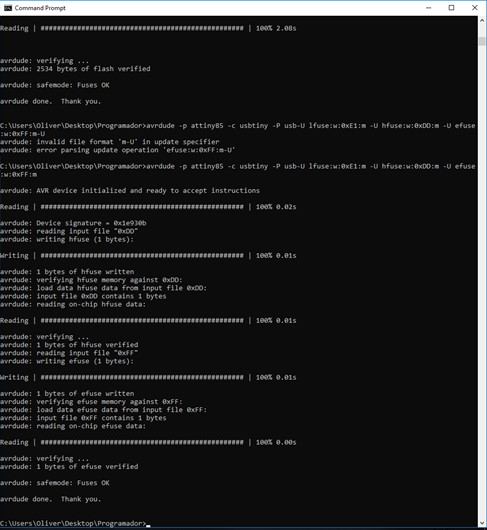
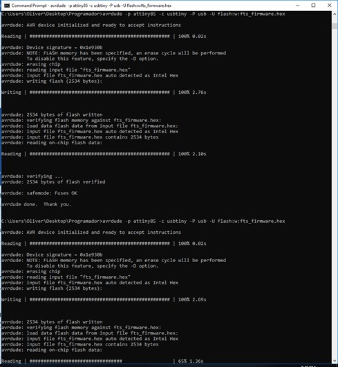
Program PCB
Program the PCB to be recognizable by a computer.
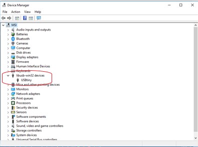
Proof
PCB being recognized by computer.
Instructions
- All of us at Fab Lab Puebla decided to make Brian's PCB
- Download images for inner (engrave) and outer lines (cut)
- Put a sacrifice bed on the Roland Mill
- Attach with double sided tape your material
- Open Fab Modules
- Start configuring to engrave the test
- Input format: PNG
- Output format: Roland Mill
- Process: PCB traces 1/64
- Define the dpi and size for the image
- Define the correct coordinates for the material to be engraved, in this case every time it was 0,0,0 because the coordinates were given by the Roland Mills Software.
- Define the zjog (space neede to change points within engraving):2 mm
- Define number of offsets, we decided to go with 4 as a standard for all engravings
- Define the tool diamater used: 4 mm
- Define Offset Overlap: 50%
- Define cut depth for engraving: 1 mm
- Calculate to obtain the final image in lines showing each offset
- Save as an .rml file to be used in the Roalnd Mill Software
- Open the SimpleFAB-20-RolandMDX software
- Define the coordenates within the yellow canvas in the Software
- Upload the .rml file
- Press Start
- Enjoy the engraving process
- The correct steps after engraving are: change the engraving tool for the cutting tool, configure in Fab Modules the outer lines for cutting, this is achieved by changing the cut depth to go all the way through the material (6mm), calculate and than process it on the software for the Roland Miller. All of this was done several times, wihtout and than with the local isntructor to understand why it wasn't cutting, after five tries and several different problem solving approaching the ranged from debugging to yelling to the Roland (we are not proud and it obviously did not work). After the instructor did several different tests the disgnose was it's not going to cut in the near future we need to give it service.
- So we wouldn't get behind on assignments we decide to cut by hand.
- After cutting it you need to sand it so it will take away the excess material at the edges.
- Add finishing touches with a dremel.
- Solder each component to the PCB.
- Test if the first LED in a computer lights.
- Try to install everything on my computer, since I don't have adminsitration permits I had to go around it.
- Connect my PCB to the tinyUDB PCB provided so I could program mine.
- Couldn't use the given file and had to program by hand directly on the command line.
- Burn and program the PCB.
- When the program is communciating the LEDs start blinking.
- Use your PCB in a USB port and check that the computer recognizes it.