Task 9
Embedded programming
In this week, I was given a task to have a group assignment and an individual assignment. The group assignment was to compare the performance and development workflows for other architectures, and the individual assignment was to read a microcontroller data sheet program your board to do something, with as many different programming languages and programming environments as possible
Individual Task
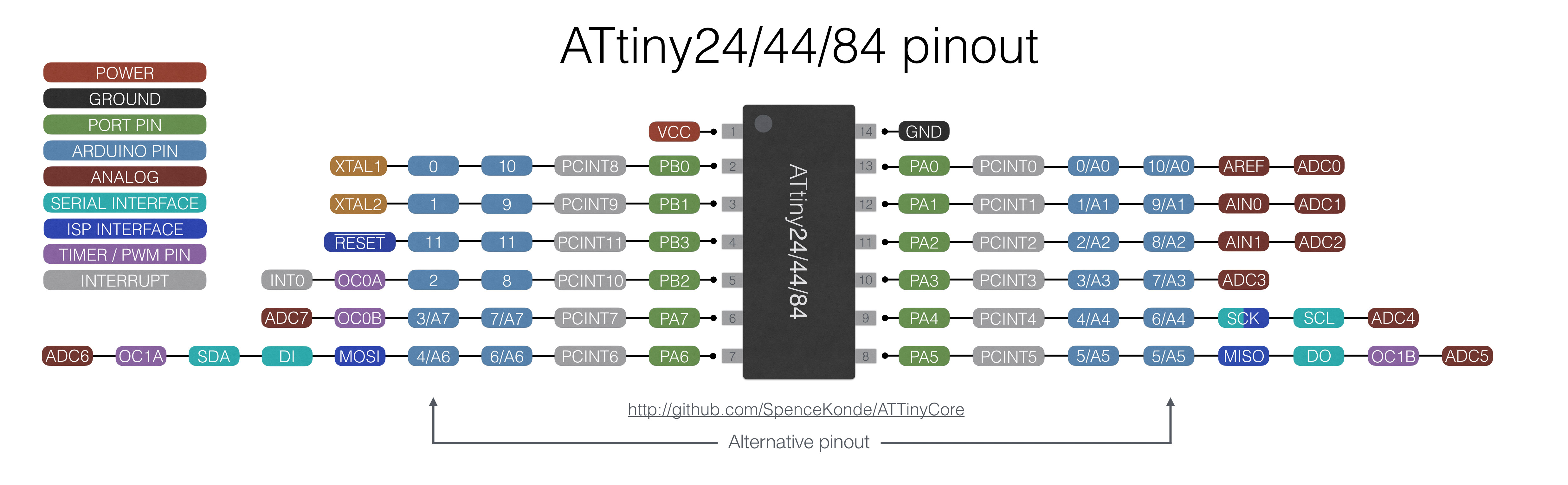
For this week, I started with the Individual work. I decided to programme the Hello-echo board that we designed in the Electronics Design week.I also need to read about a ATtiny24A/44A/84A microcontroller datasheet.
Studying the Datasheet
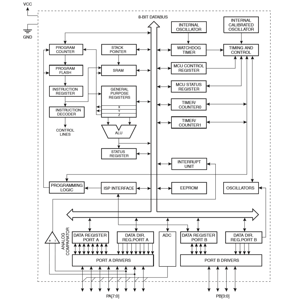
ATtiny44 is a microcontroller from AVR Microcontroller family. It is a High performance, low power ,8 bit microcontroller.It follows advanced RISC Architecture ..
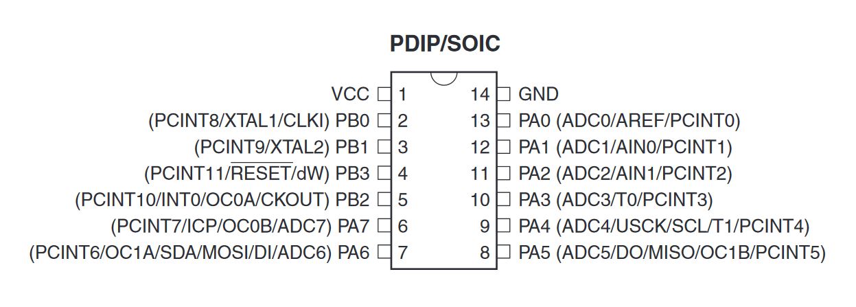
- Pin Descriptions are as follows:
- VCC: It provides the supply voltage.
- GND:
- Port B (PB3:PB0): It is a I/O Port with boidirectional data transfer
- Port A (PA7:PA0): It is also a 8-bit I/O bidirectional board with internal pul up resistor.
- RESET: It is an inverted RESET pin.A low level pulse more than minimum length will reset pin
Programming the Board
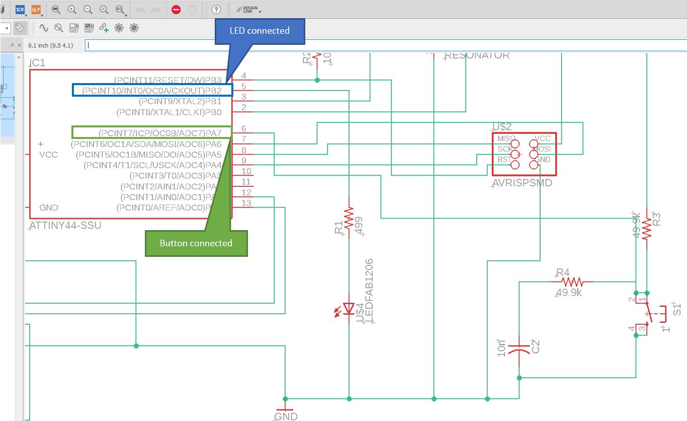
In order to program the board i have to identify the ports to which LED and Button are connected.So i refered my schematic to find the ports to which both components are connected.
There is several ways to prograamme a AVR Microcontroller. Easiest one is using Arduino IDE, Atmel Studio 7 also we have toolchain in GCC. First I used Arduino IDE. I am using the FabTiny ISP as our Programmer.
- Arduino IDE Pin Map for LED and Button:
- 8: LED
- 7: Button Atmel Studio 7 Pin Map for LED and Button:
- PB2: LED
- PA7: Button
Programming ATtiny44 with ARDUINO
Arduino is an open source computer hardware and software company, project, and user community that designs and manufactures single-board microcontrollers and microcontroller kits for building digital devices and interactive objects that can sense and control objects in the physical and digital world. The Arduino system is based on the avr-gcc compiler and makes use of the standard AVR libc libraries, which are open-source C libraries, specifically written for Atmel hardware.You can downdload the Arduino IDE here. Now arduino also have Online IDE.
ARDUINO IDE : Settings
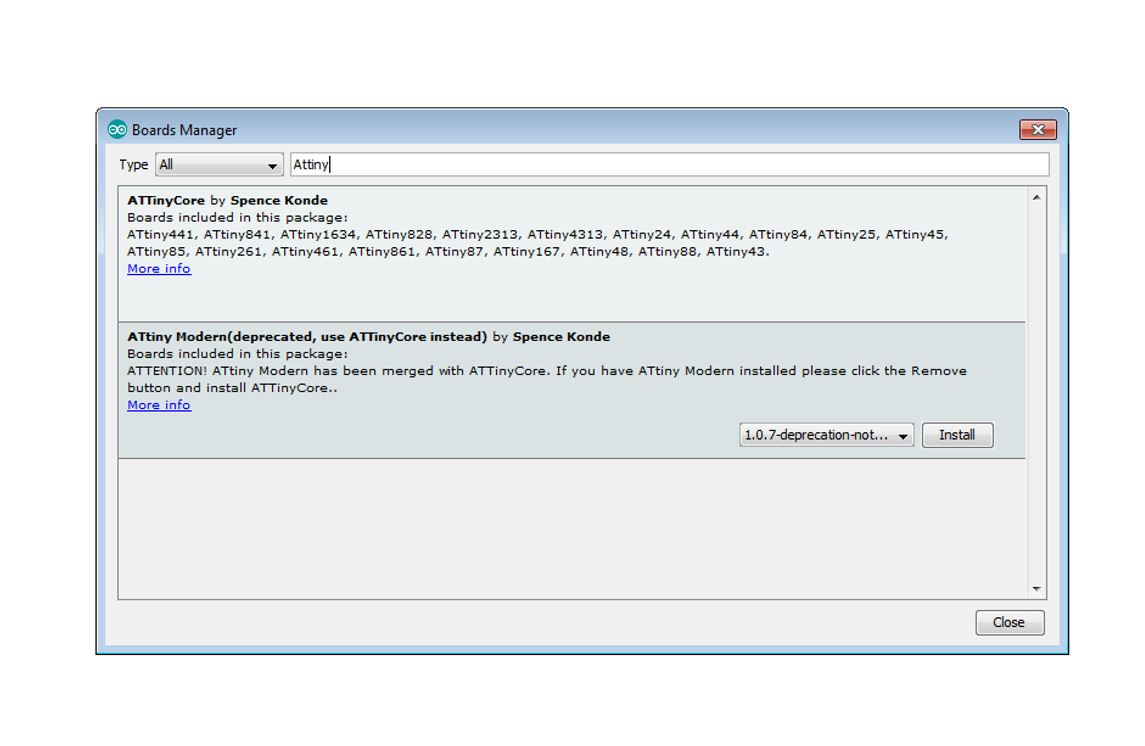
- By default the arduino software doesnt contain Attiny 44 chip librarys. We need to include the details manually.
- Install and Open Arduino IDE
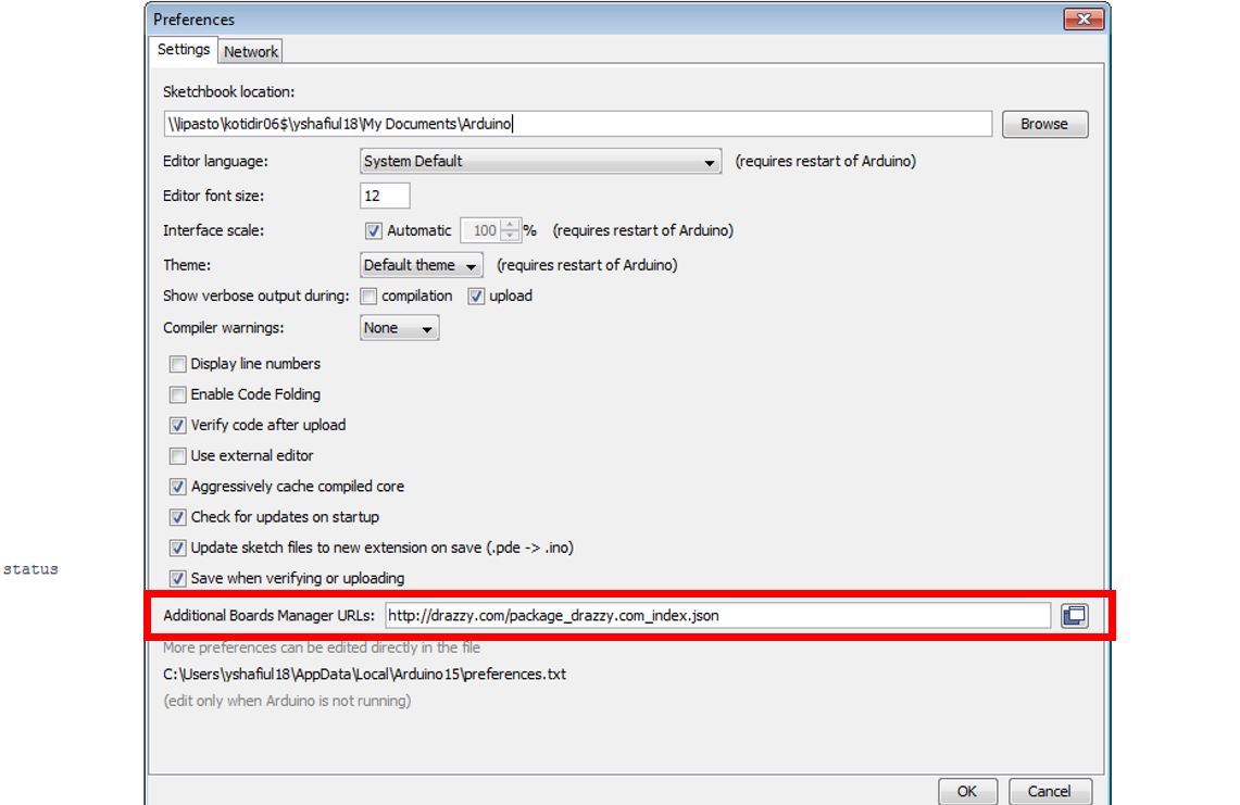
- Open preference by clicking File >> preference
- In Additional Board Manager URls add the Following URL http://drazzy.com/package_drazzy.com_index.json
- After adding the URL open Board Manager by clicking Tools >> Board >> Board Manager. Now we can select ATtiny44 under the ATtiny Microcontrollers in board Selection
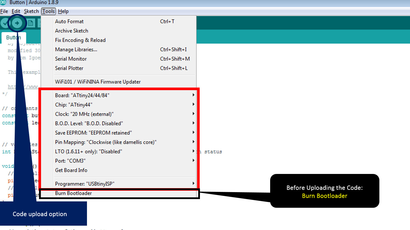
- Select appropriate Clock and Programmer.
- I am using the USBtiny programmer which we made during the Week 5 assignment to programme the Hello-Echo board so Select the Programmer as USBtinyISP.
- The ISP Programming of ATtiny 44 using six pins .These are the 6 pins
- SCK(Serial Clock): Programming clock, generated by the In-System Programmer (Master)
- MOSI(Master Out - Slave In): Communication line from In-System Programmer (Master) to target AVR being programmed (Slave )
- MISO( Master In - Slave Out ): Communication line from target AVR (Slave) to In- System Programmer (Master)
- RST(Reset): To enable In-System Programming, the target AVR Reset must be kept active. To simplify this, the In-System Programmer should control the target AVR Reset
- GND(Ground): Common Ground
- Blink Code with button: Blinks the LED with a push button
- Blink with delay Code: Blinks the LED with an ON time of 30ms and OFF time of 60ms
- Blink with Multiple delay Code: Blinks the LED with an multiple delays in between ON and OFF time
The next step is to execute the code, but before executing any code select Burn Bootloader option which will make the fuses and connect the board. For burning the bootloader, USBtinyISP is needed to be connected.
- For Beginners in programming, I found this book to be useful. I started with a simple code initially to observed the working of the program. then I advanced, below are codes and the result acheived:
ARDUINO IDE : LED Blink Code with button
// constants won't change. They're used here to set pin numbers:
const int buttonPin = 7;     // the number of the pushbutton pin
const int ledPin =  8;      // the number of the LED pin


// variables will change:
int buttonState = 0;         // variable for reading the pushbutton status

void setup() {
  // initialize the LED pin as an output:
  pinMode(ledPin, OUTPUT);
  // initialize the pushbutton pin as an input:
  pinMode(buttonPin, INPUT);
}


void loop() {
  // read the state of the pushbutton value:
  buttonState = digitalRead(buttonPin);

  // check if the pushbutton is pressed. If it is, the buttonState is HIGH:
  if (buttonState == LOW) {
    // turn LED on:
    digitalWrite(ledPin, HIGH); // turn the LED ON by making the voltage LOW


  } else {
    // turn LED off:
    digitalWrite(ledPin, LOW); // turn the LED OFF by making the voltage LOW
  }
}
ARDUINO IDE : LED Blink with delay Code
// constants won't change. They're used here to set pin numbers:
const int buttonPin = 7;     // the number of the pushbutton pin
const int ledPin =  8;      // the number of the LED pin


// variables will change:
int buttonState = 0;         // variable for reading the pushbutton status

void setup() {
  // initialize the LED pin as an output:
  pinMode(ledPin, OUTPUT);
  // initialize the pushbutton pin as an input:
  pinMode(buttonPin, INPUT);
}


void loop() {
  // read the state of the pushbutton value:
  buttonState = digitalRead(buttonPin);

  // check if the pushbutton is pressed. If it is, the buttonState is HIGH:
  if (buttonState == LOW) {
    // turn LED on:
    digitalWrite(ledPin, HIGH);
     delay(30);                       // wait for a second
  digitalWrite(ledPin, LOW);    // turn the LED off by making the voltage LOW
  delay(60);

  } else {
    // turn LED off:
    digitalWrite(ledPin, LOW);
  }
}
ARDUINO IDE : LED Blink with Multiple delay Code
// constants won't change. They're used here to set pin numbers:
const int buttonPin = 7;     // the number of the pushbutton pin
const int ledPin =  8;      // the number of the LED pin


// variables will change:
int buttonState = 0;         // variable for reading the pushbutton status

void setup() {
  // initialize the LED pin as an output:
  pinMode(ledPin, OUTPUT);
  // initialize the pushbutton pin as an input:
  pinMode(buttonPin, INPUT);
}


void loop() {
  // read the state of the pushbutton value:
  buttonState = digitalRead(buttonPin);

  // check if the pushbutton is pressed. If it is, the buttonState is HIGH:
  if (buttonState == LOW) {
    // turn LED on:
    digitalWrite(ledPin, HIGH);
     delay(20);                       // wait for a second
  digitalWrite(ledPin, LOW);    // turn the LED off by making the voltage LOW
  delay(30);
  digitalWrite(ledPin, HIGH);
     delay(60);                       // wait for a second
  digitalWrite(ledPin, LOW);    // turn the LED off by making the voltage LOW
  delay(10);
  digitalWrite(ledPin, HIGH);

  } else {
    // turn LED off:
    digitalWrite(ledPin, LOW);
  }
}
Programming ATtiny44 with Atmel Studio 7
Atmel Studio we use Avr C language which is a bit difficult compared to the Arduino. Here we got to have a thorough knowledge of Microcontroller registers, logic circuits and things like that. This is where the datasheets could help us. To start programming our board using Fab ISP we have to first configure our ATmel studio. Before this first download your Atmel Studio 7.
Atmel Studio 7 : Settings
- By default the arduino software doesnt contain Attiny 44 chip librarys. We need to include the details manually.
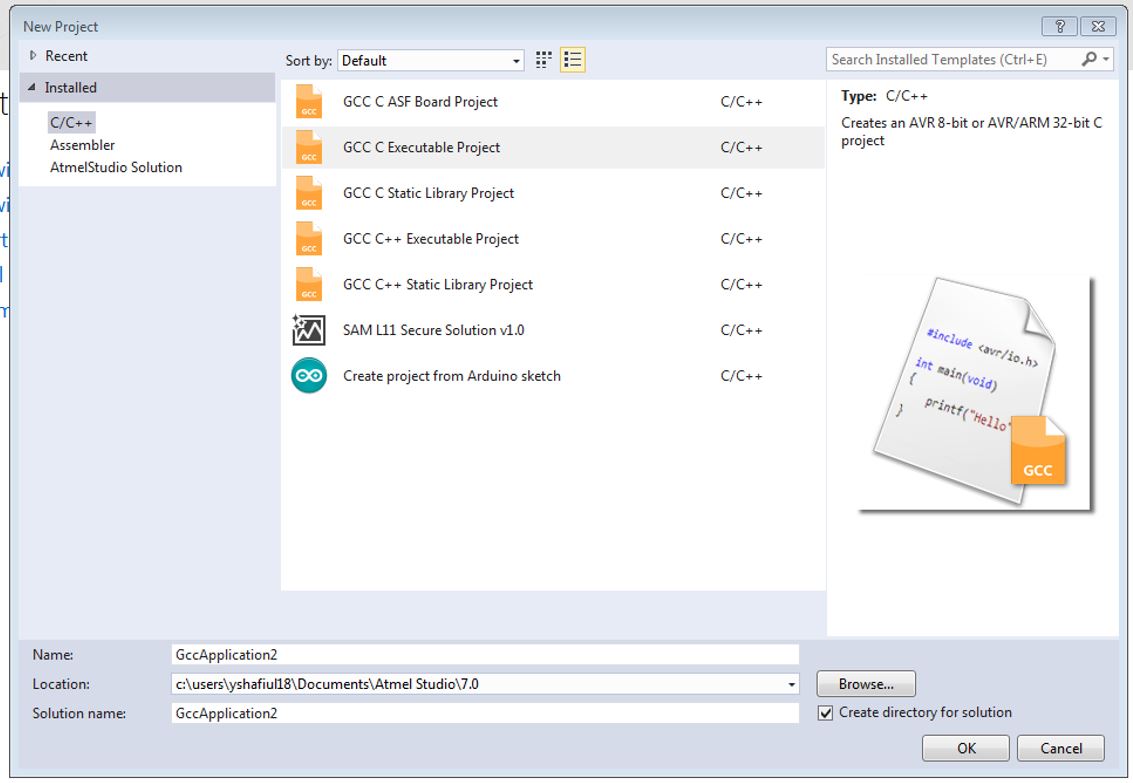
- Install and Open Atmel Studio 7
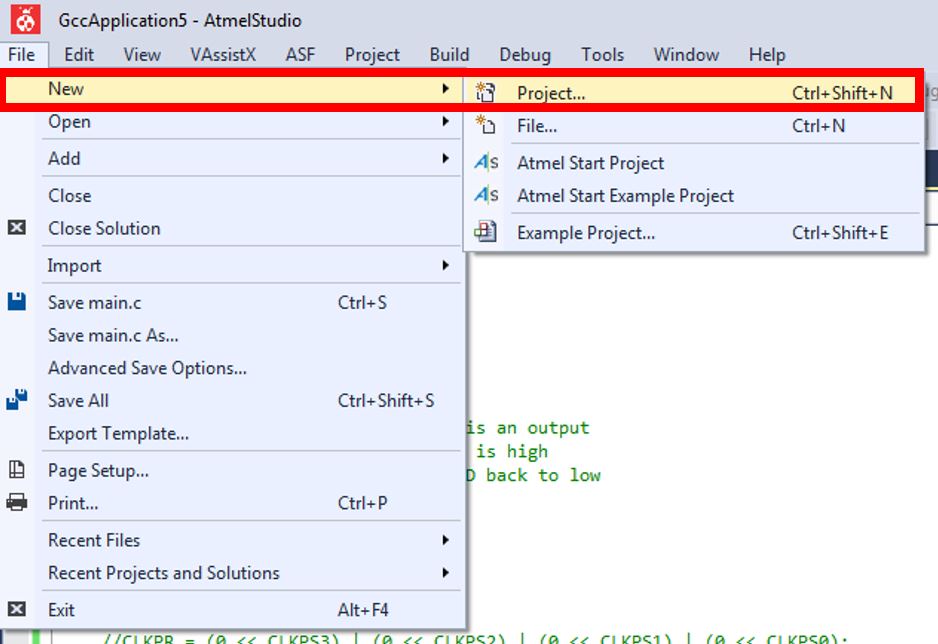
- Start a new project goto File-->New-->Project
- In the window select C/C++ as language and select the second one from the selected list
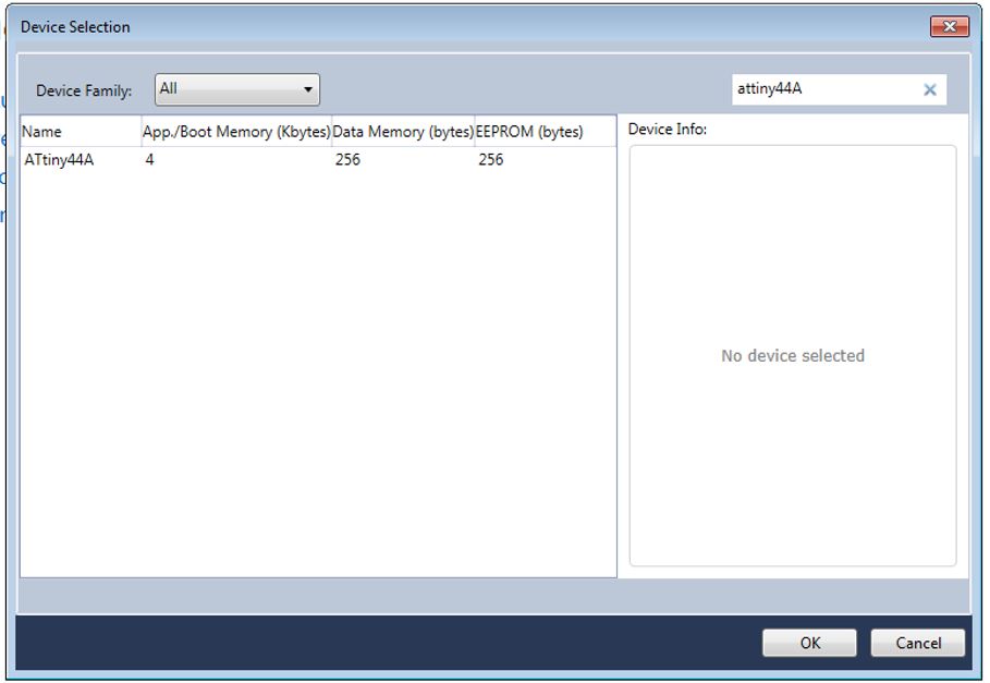
- Select Attiny as the device family and select Attiny44A from it and press OK.
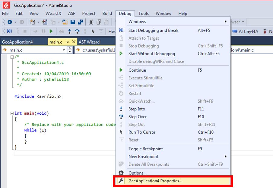
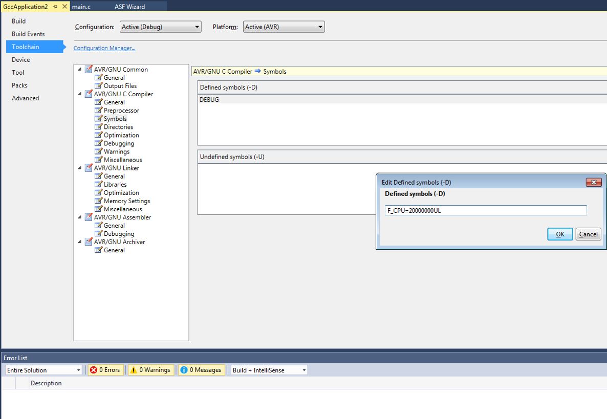
- Goto Debug-->GccApplication4 Properties, Define the External/Internal Clock i.e in my case External Clock : 20000000UL
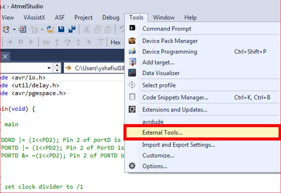
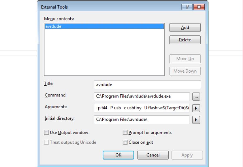
- Next we have to add our programmer to our enviorment. Choose Tools -> External Tools -> Fill the spaces as shown below.
- Command : C:\Program Files\avrdude\avrdude.exe [avrdude.exe destination]
- Arguments : -p t44 -P usb -c usbtiny -U flash:w:$(TargetDir)$(TargetName).hex:i
- Initial Directory : C:\Program Files\avrdude\
I tried a simple code to blink the LEDs in my board.
- Before starting the programming a little bit about the programming:
- DDRx - Port X Data Direction Register stands for Data direction Register, basically it is an 8-bit register which determines whether one pin will be an input or output pin. If you want the pin you connected the LED to be set as output then you should give that value of that as 1 on DDRx. Example I connected my LED to PA7, hence I have to make it as out put in DDRA. Hence I give the code to set the pin PA7 as out put by writing. DDRA=0xff; This is HEX equivalent for DDRA=ob11111111 What this does is that it will set all the pins on the PA7 as output pins
- PORTx - Port X Data Register PORTx is an 8-bit register which stores the logic values, while DDRx denotes the direction of the Pin, PORT denotes the state of it. That means if I give a value 1 in the PORT register of that pin It would be set to HIGH, or 5V in case of the micro controller.
- PINx - Port X Input Pins Register PINx is an 8-bit register that stores the logic value, It is a dynamic register whose value will be automatically updated based on the received values of the sate of all pins, so 5V to that pin will write 1 to that register.
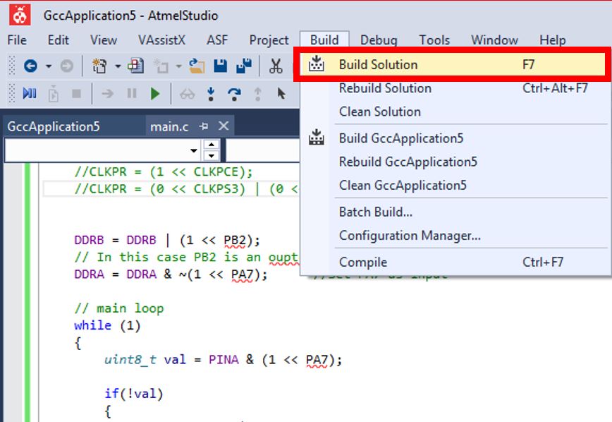
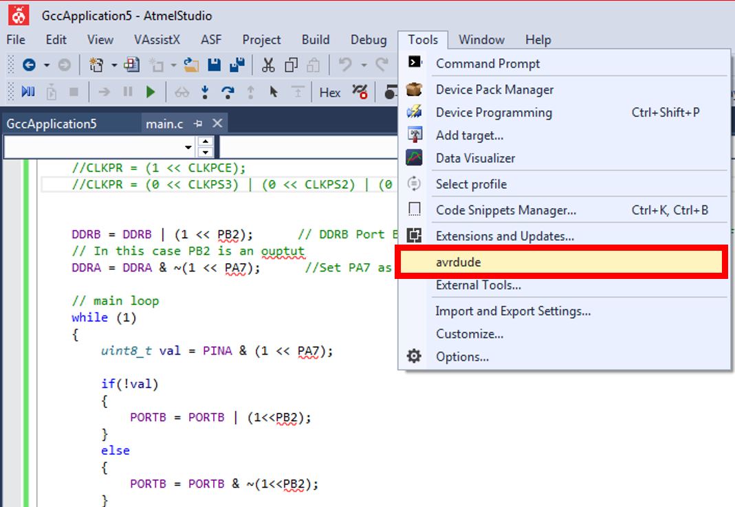
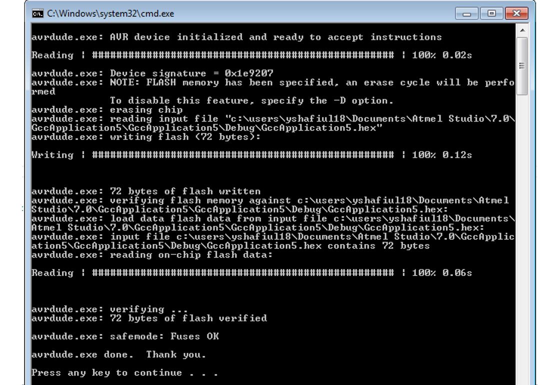
Now Lets start programming, to compile the code Goto Build-->Build Solution. After building, the next step is to finally flash the code by clicking Tools-->avrdude. I used and modified IVÁN code to program my board
ATMEL Studio 7 : LED Blink Code with button
#include < avr/io.h >
#include < util/delay.h >
#include < avr/pgmspace.h >

int main(void) {
	//
	// main
	//
	//DDRD |= (1 << PD2); Pin 2 of portD is an output
	//PORTD |= (1 << PD2); Pin 2 of PortD is high
	//PORTD &= ~(1 << PD2); Pin 2 of PORTD back to low


	//
	// set clock divider to /1
	//
	//CLKPR = (1 << CLKPCE);
	//CLKPR = (0 << CLKPS3) | (0 << CLKPS2) | (0 << CLKPS1) | (0 << CLKPS0);


	DDRB = DDRB | (1 << PB2);      // DDRB Port B Data Direction Register. Selects direction of pins
	// In this case PB2 is an ouptut
	DDRA = DDRA & ~(1 << PA7);      //Set PA7 as input

	// main loop
	while (1)
	{
		uint8_t val = PINA & (1 << PA7);

		if(!val)
		{
			PORTB = PORTB | (1 << PB2);
		}
		else
		{
			PORTB = PORTB & ~(1 << PB2);
		}

	}
}
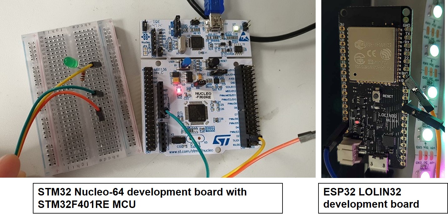
Group Task
For group work, we tested the STM32 Nucleo-64 development board with STM32F401RE MCU and ESP32 LOLIN32 development board using Arduino IDE. The STM32 family of 32 bit Flash microcontrollers based on the ARM® Cortex® M processor is designed to offer new degrees of freedom to MCU users. It offers a 32 bit product range that combines very high performance, real-time capabilities, digital signal processing, and low power, low voltage operation, while maintaining full integration and ease of development. More details of the can be found in the STM32f401RE Datasheet
On the other hand, ESP32 is a low-cost, low-power system on a chip (SoC) series with Wi-Fi & dual-mode Bluetooth capabilities! The ESP32 family includes the chips ESP32-D0WDQ6 (and ESP32-D0WD), ESP32-D2WD, ESP32-S0WD, and the system in package (SiP) ESP32-PICO-D4. At its heart, there's a dual-core or single-core Tensilica Xtensa LX6 microprocessor with a clock rate of up to 240 MHz. ESP32 is highly integrated with built-in antenna switches, RF balun, power amplifier, low-noise receive amplifier, filters, and power management modules. Engineered for mobile devices, wearable electronics, and IoT applications, ESP32 achieves ultra-low power consumption through power saving features including fine resolution clock gating, multiple power modes, and dynamic power scaling. More details can be found in the ESP32 Datasheet
Initially, we Installed the Board managers necessary for STM32F3, then followed by defining the board information in tools in similar step as we selected the ATtiny44A board programming earlier here we selected Nucleo-64, board part number Nucleo F303RE and then ran the test code to blink the LED. The below video demonstrates the code implemented and board setup details can be observed on the Lukasz page.
This Tutorial link was being followed next to install ESP32 board in Arduino IDE. The steps are almost similar to Individual assignment for Arduino IDE for programing the ESP32 LOLIN32 development board. See the below first picture present STM32F4 and second picture which present LED blinking programmed for ESP32 board using Arduino IDE
Resources Utilized
- I utilized these resources for this task:
- Arduino IDE
- Atmel Studio 7