Task 6
3D Scanning and printing
In this week, I was given a task to have a group assignment and an individual assignment. The group assignment was to Test the design rules for your 3D printer(s), and the individual assignment was to design and 3D print an object (small, few cm3, limited by printer time) that could not be made subtractively. 3D scan an object (and optionally print it)
Group Task
The group assignment was to Test the design rules for your 3D printers. For this purpose a ready test file was downloaded from https://www.thingiverse.com/thing:1363023. Furthermore, three printers were selected in the FAB Lab to print this 3D Model to have a good comparison :
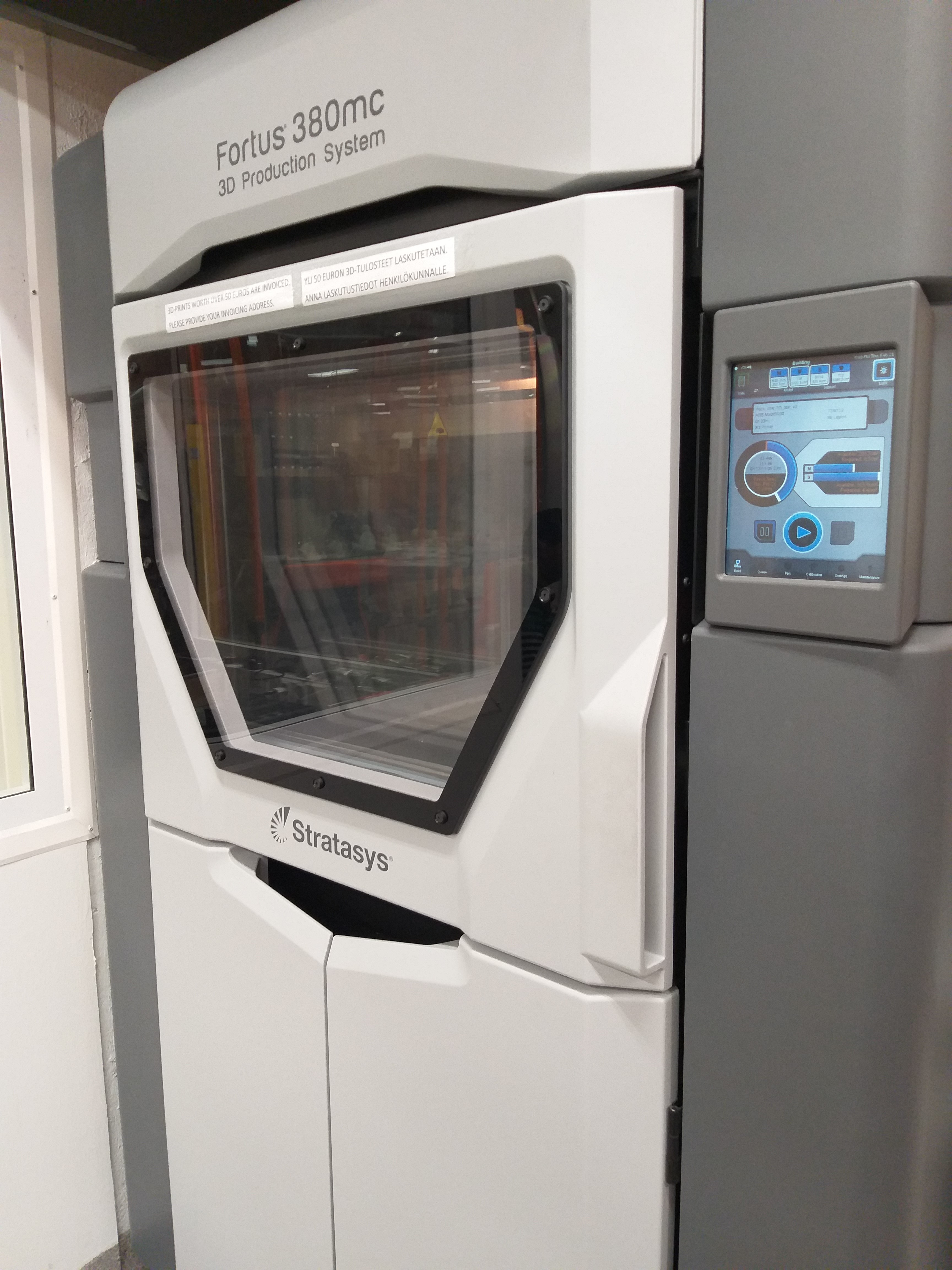
Group Task :: Printer 01 (Stratasys Fortus 380MC 3D):
The below are the Stratasys Fortus 380MC 3D specifications:
- Build volume:
- 3D print size : Medium
- Print size millimeters (xyz) : 355 x 305 x 305 mm
- Print size inches (xyz): 14 x 12 x 12 inches
- 3D printer and printing properties
- Layer height : 127 - 330 Microns
- Closed print chamber : Yes, fully enclosed
- Connectivity : 10/100 base T connection. Ethernet protocol.
- Requirements
- Software : "InsightTM, Control CenterTM, GrabCad
- Operating system(s) : Windows Vista, 7, 8, 8.1
- Power requirements : 208VAC 3 phase, 50/60 Hz, consumes 18 Amps
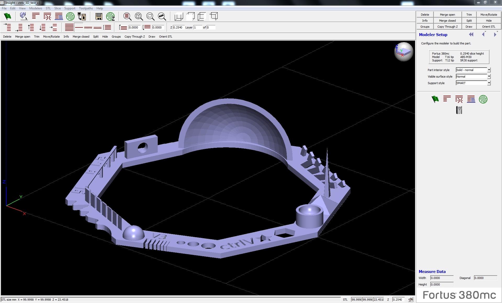
The InsightTM was being utilized for this purpose. The Tutorial was quite helpful to get an Initial Start. The Test file (.stl format) which was download from https://www.thingiverse.com/thing:1363023 was being initilally opened in the Software. The ABS was being utilized due to its good strength, temperature resistance and more susceptible to warping.
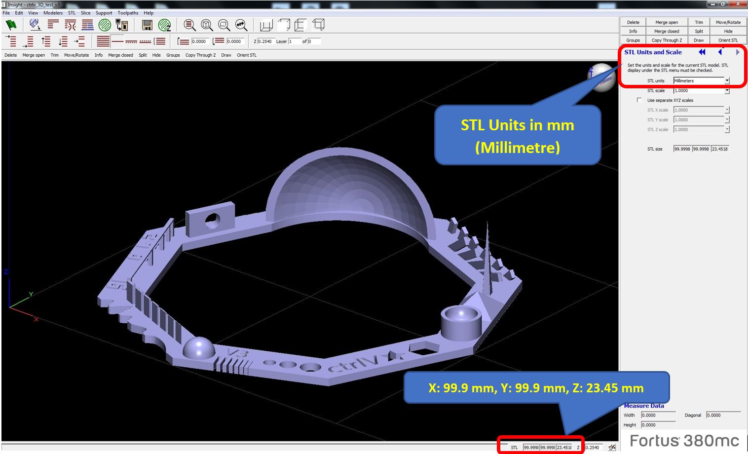
The Next step was to check the units which can be checked with "STL units and scale" is also marked in the picture, The units are in "mm (millimeter)" as seen below in the picture representation as well.
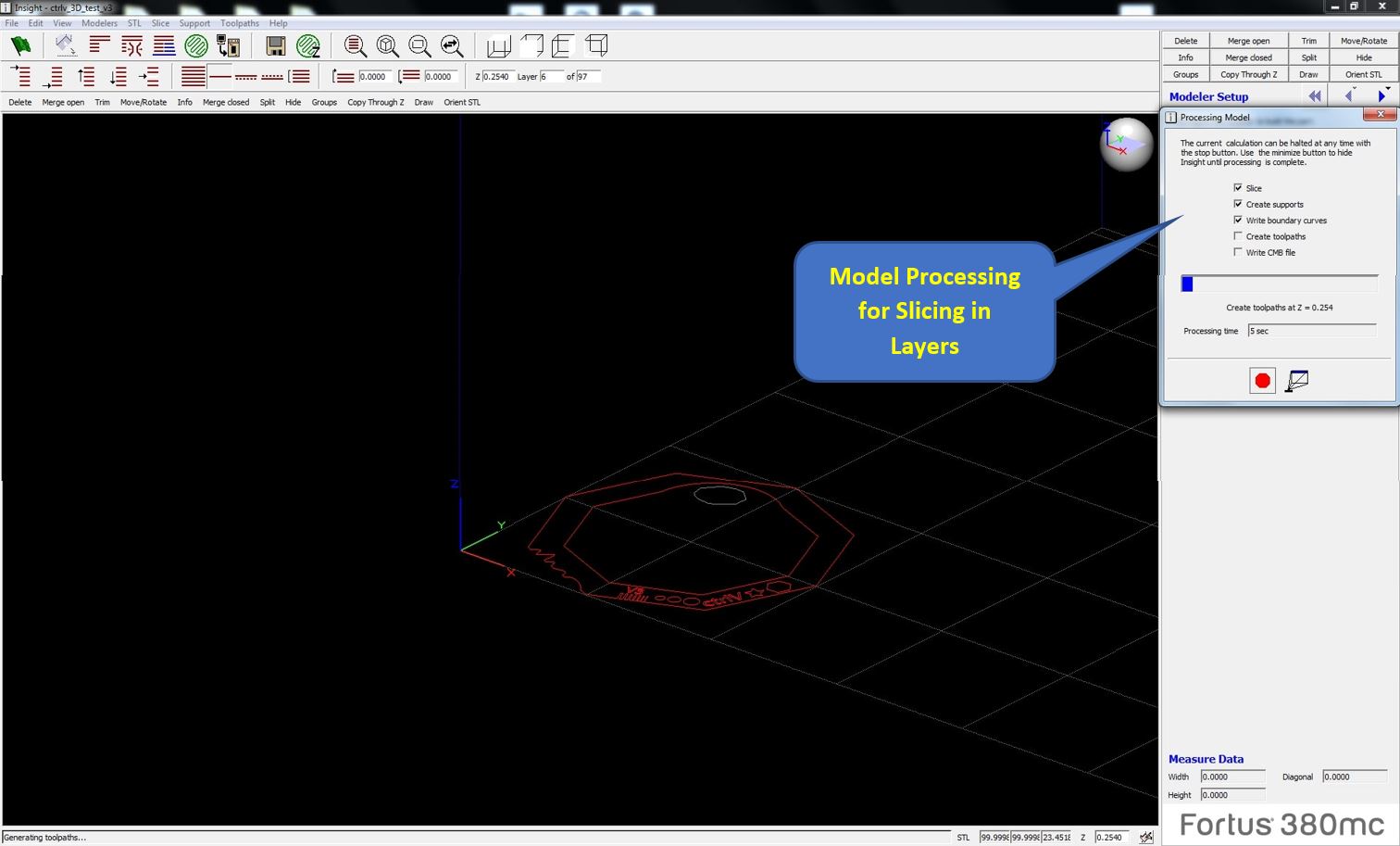
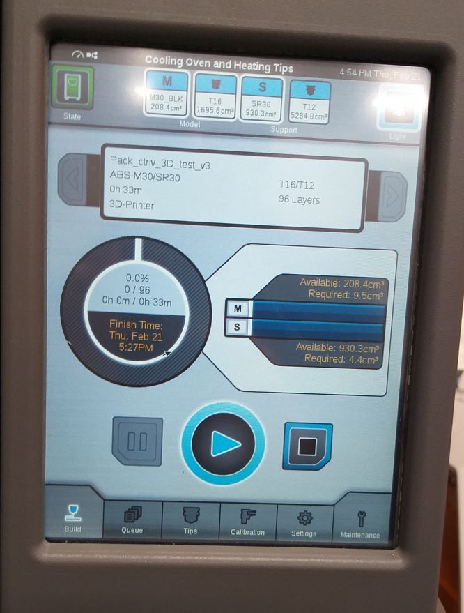
After Checking the units, we will slice up the model into layers, Since the 3D Printer prints in Layers. For this purpose we use the Slice button to Slice the model in layers. The slicing of the model begins, it takes a few seconds. The slice operation computes part curves by analyzing cross sections of the STL file. The slice operation begins at the sections of the STL file. The slice operation begins at the bottom of the model and progresses sequentially to the top at a constant interval, or slice height. The value of slice height is based on the material and tip size used in your modeler. Stratasys recommends using the default values.

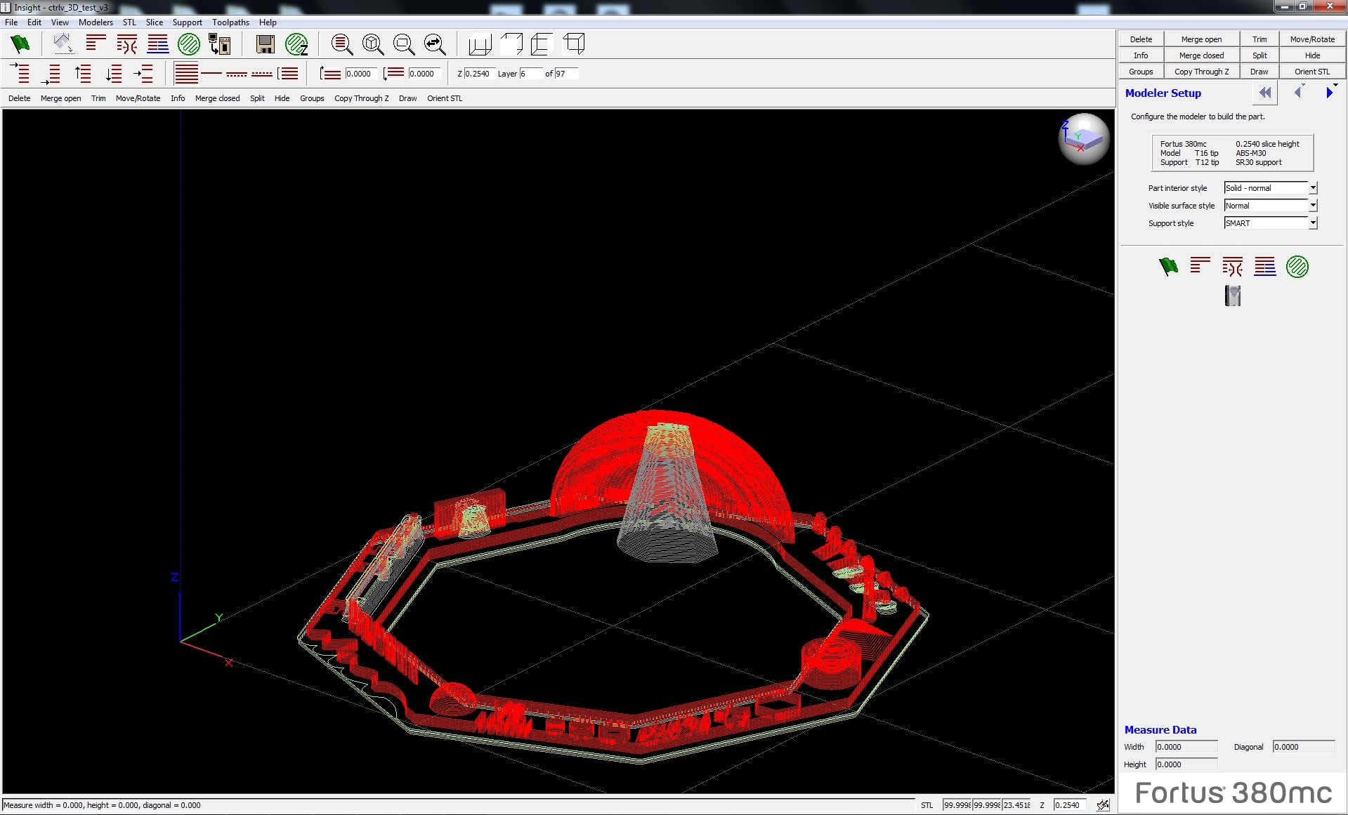
The below is the model created after slicing, with different red lines as the layers depicting how the layers will be printed in the 3D printers.
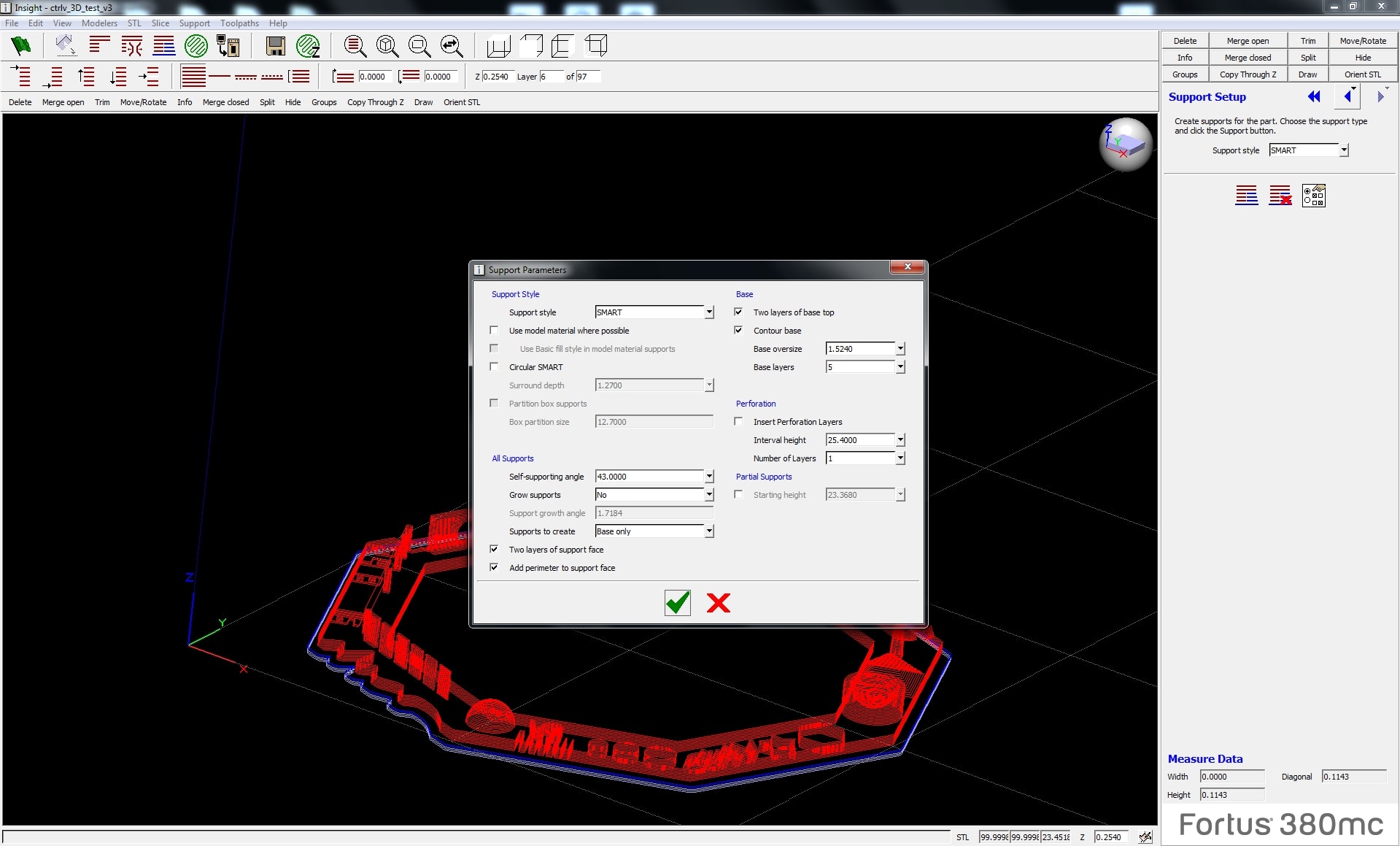
The supports settings need to be checked carefully before printing, In our case we selected the support to be "Base only" since we required support material at the base. There are other settings as well and one of them is "Supports Extended for Base".
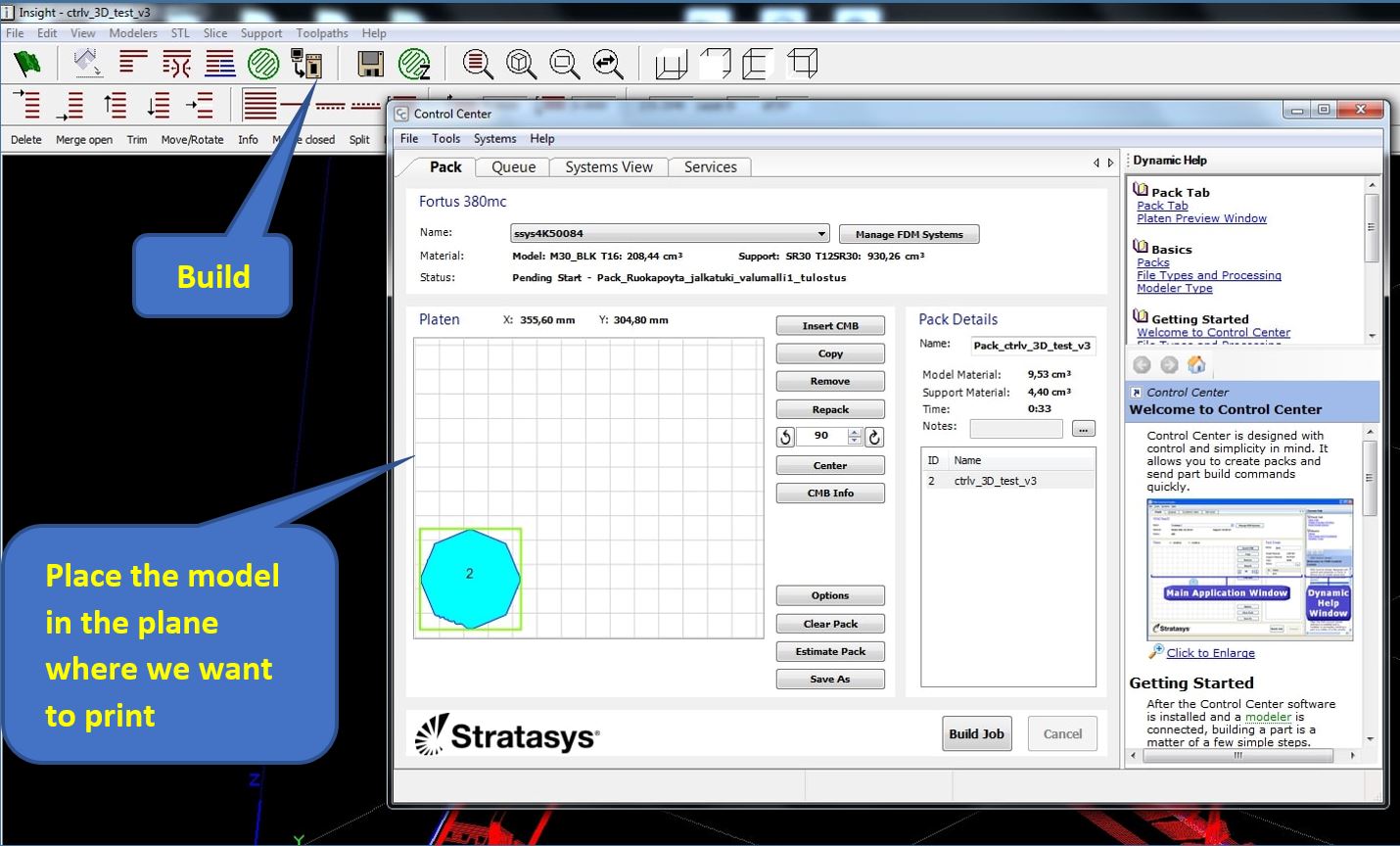
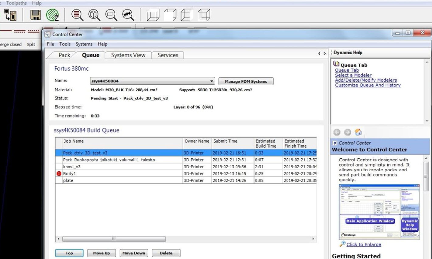
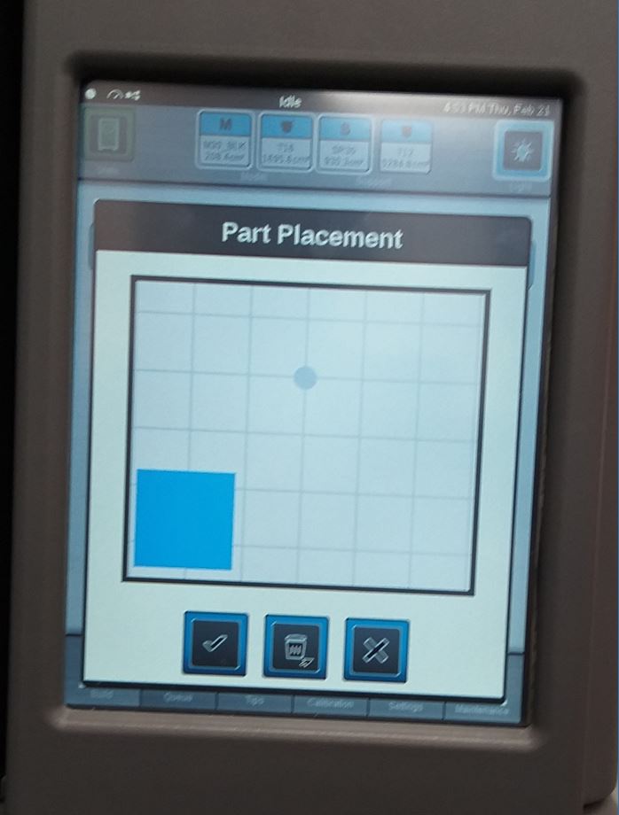
After checking the support settings we go for the final stage of printing, we select "Build" and allign the position of our model in the 2D plane where we are willing to print. The Task will be in queue and we can prioritize our task in the queue as well. Wear the gloves and place the Foundation sheet inside the chamber where the 3D Design will be printer. After putting the design in queue, we can check the Stratasys Printer LCD Screen as well to see our task. Select your task, there is a Play Button to begin the task. Another window will open which will inquire about the Part Placement of location where the 3D printing shall begin. Touch the LCD to place the part and click the Tick symbol. The printing will begin.
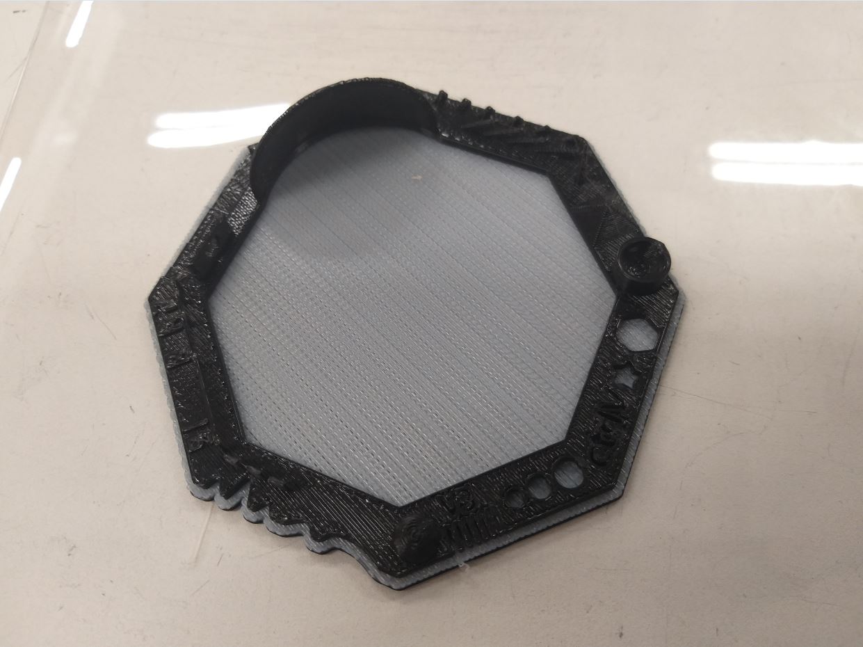
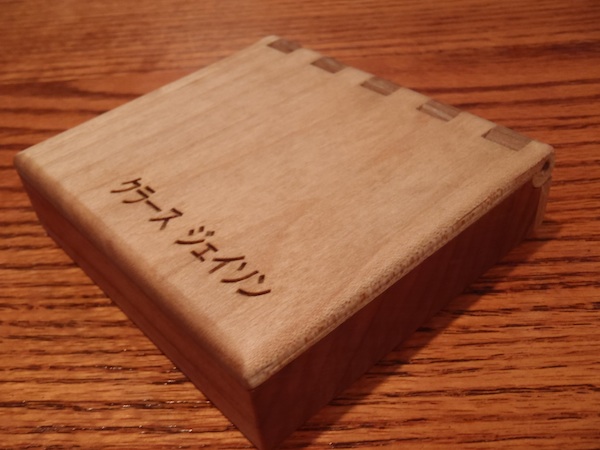
The 3D Printed model is printed, with a Base Support. The Base Support is being removed and the Printed 3D part can be seen in the Picture. Since it was our 3D print, it was really amazing to observe such details the printer can print in 3D.
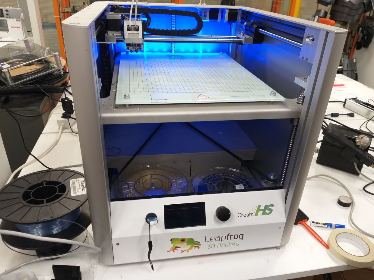
Group Task :: Printer 02 (LeapFrog 3D):
The below are the LeapFrog 3D specifications:
The slic3r software was being utilized for this purpose. Open ‘Arkkitehtehtuuri 3D’ Folder --> Sli3erPE --> slic3r --> (name of printer: creator HS) The PLA material was being utilized. The support material PVA (water soluble support material) was being used. The .stl file was opened using the slic3r
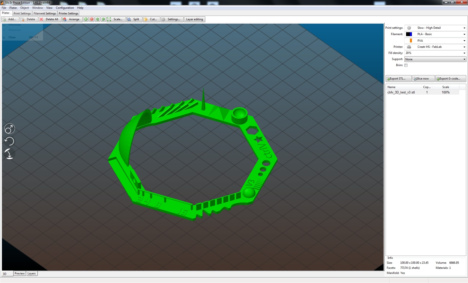
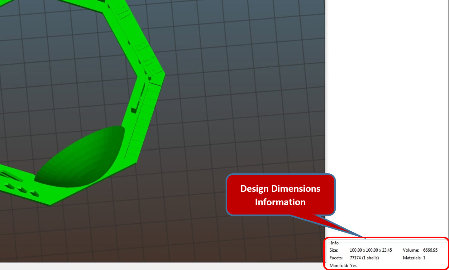
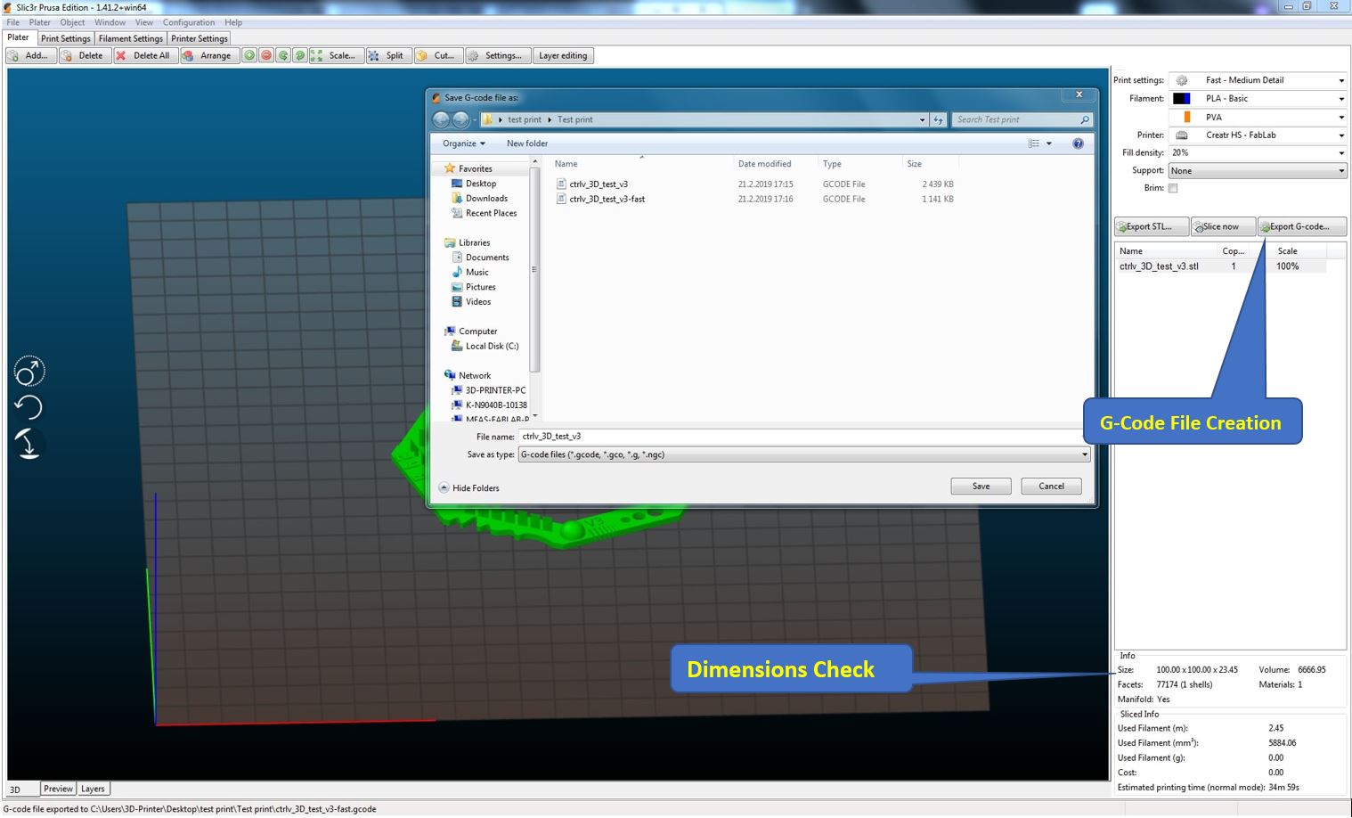
The .stl file format of the model was being opened in the slic3r, and the Model can be seen below in green colour. The Dimensions of the design can be verified on the right bottom end of the window which demonstrates the Size in mm (millimeters).
After confirming the dimensions of the design, In this Printer we have to create the G-Code file. A GCODE file contains commands in G-Code, which is a language used to describe how a 3D printer should print a job. It stores instructions in plain text with each line representing a different command, such as how fast the printer should print, the temperature it should be set at, and where the printing parts should move. The G-Code file can be created by pressing the Export G-Code button as mentioned in the picture below as well.
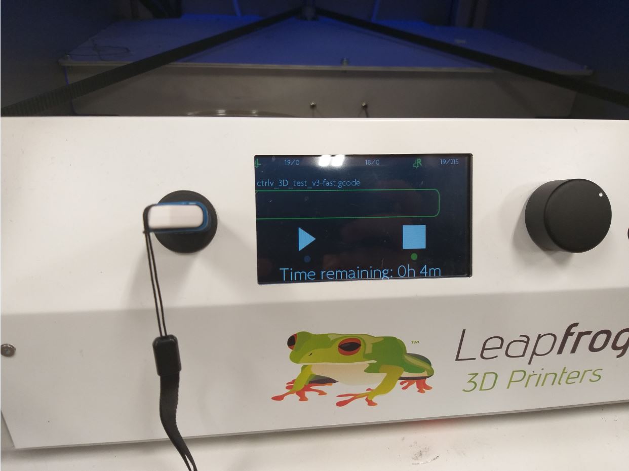
The Created G-code file is then taken in USB from the Computer and the LeapFrog machine has a USB port where the USB can be attached and from the screen the command to print can be initiated by selecting the file in the USB and pressing the play button which begins the printing.
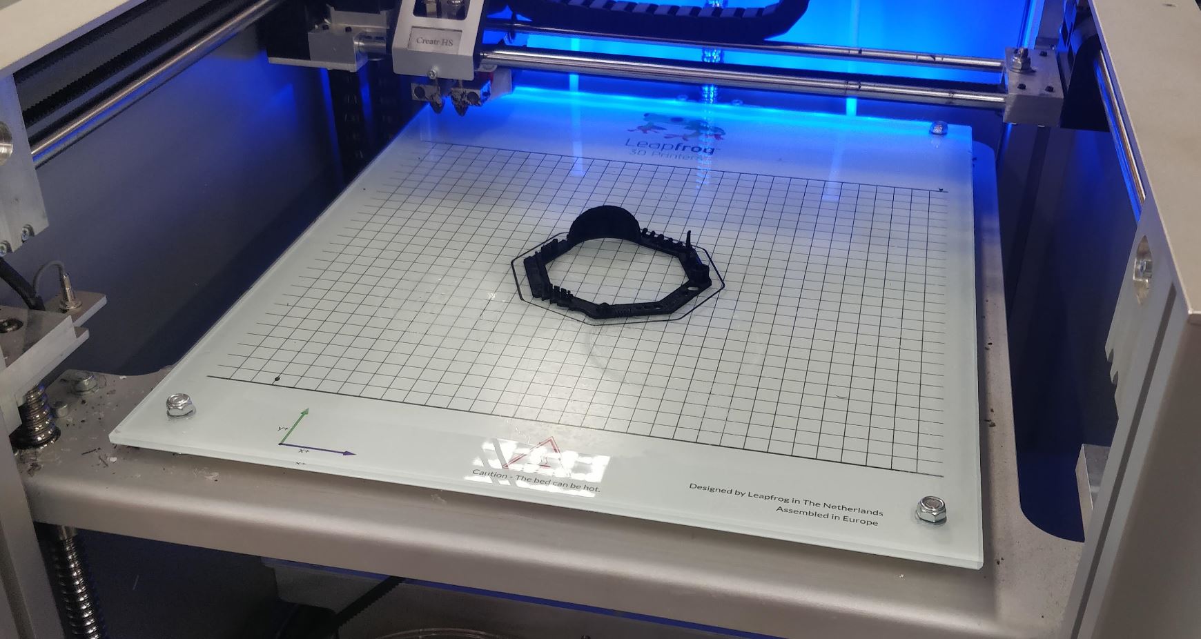
After printing, the design came up and we just have to remove the design from the platform being attached. The printed design was printed as the 3D file.
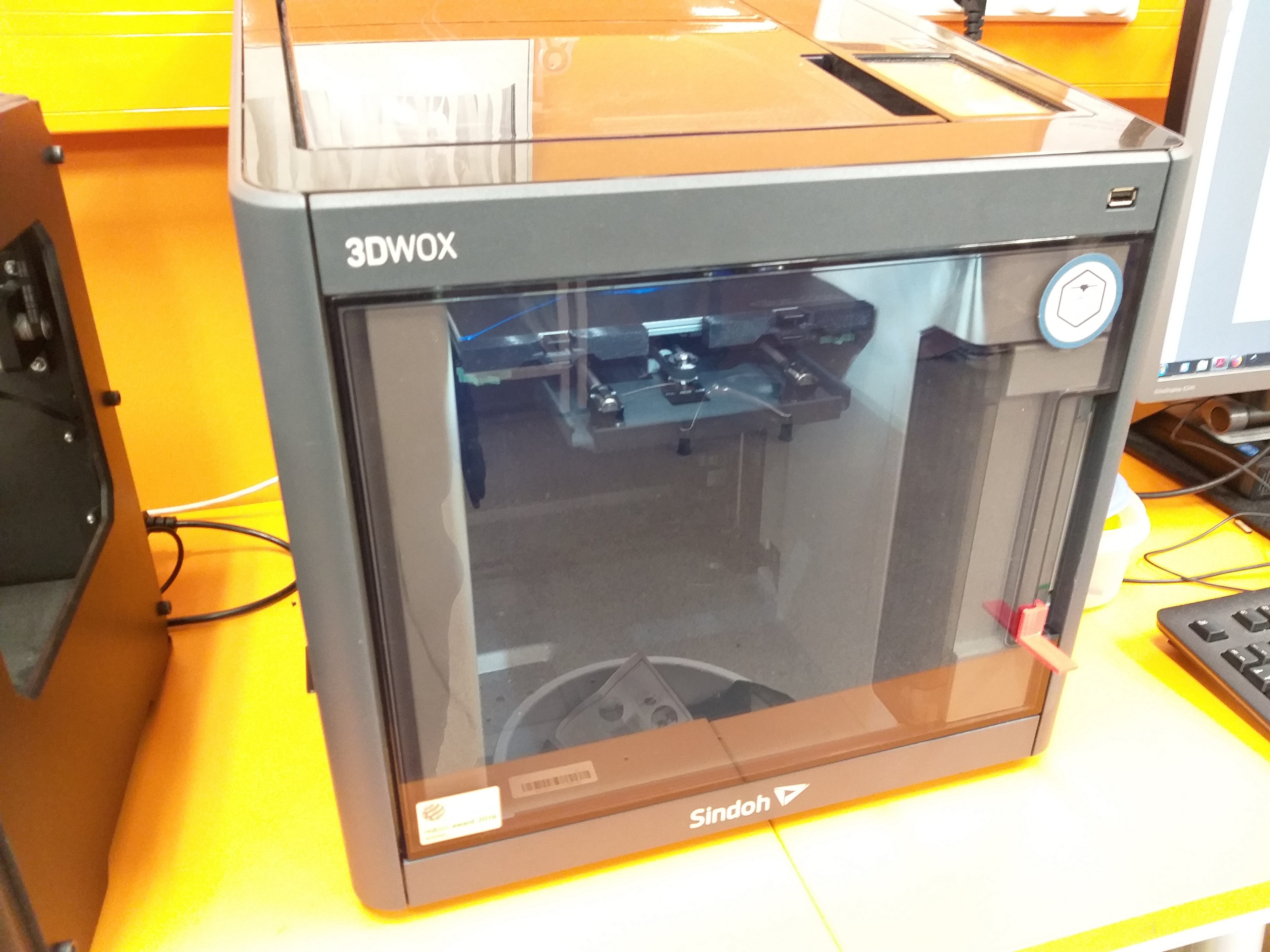
Group Task :: Printer 03 (Sindoh 3D VOX):
The below are the Sindoh 3D VOX specifications:
- Build volume:
- 3D print size : Medium
- Print size millimeters (xyz) : 228 x 200 x 300 mm
- Print size inches (xyz): 8.9 x 7.9 x 11.8 inches
- 3D printer and printing properties
- Layer height : 20 – 200 Microns
- Nozzle size: : 0.4 mm
- Closed print chamber : Yes, fully enclosed
- Connectivity : Ethernet, USB cable, Wi-Fi.
- Requirements
- Software : 3DWOX
- Operating system(s) : Windows
Moving onto our next printer, The Sindoh 3DWOX software was being utilized for 3D printing purpose. The Tutorial 1, Tutorial 2 and Tutorial 3 was very helpful to start with the printer. The PLA material was being utilized. The support material is also the same. The .stl file was opened using the Sindoh 3DWOX software.
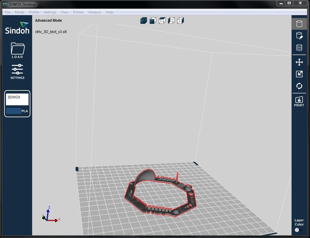
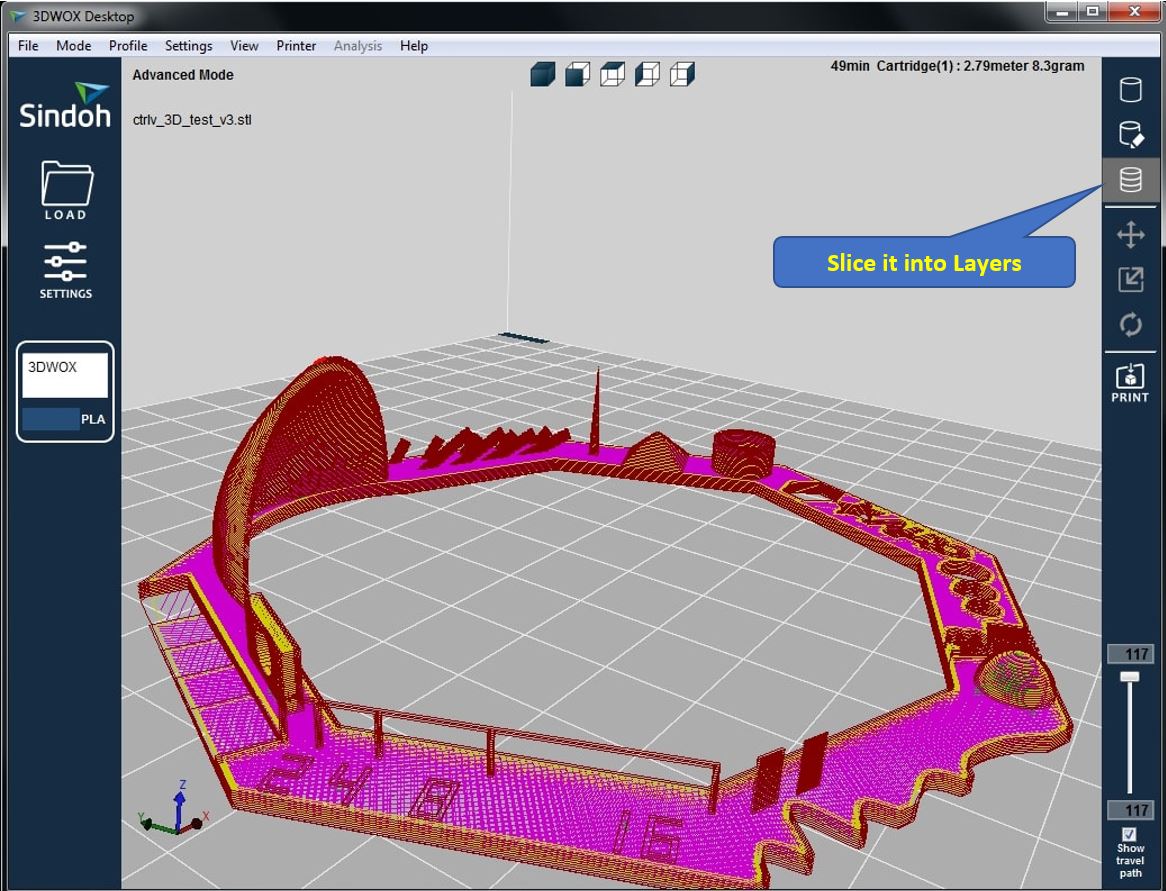
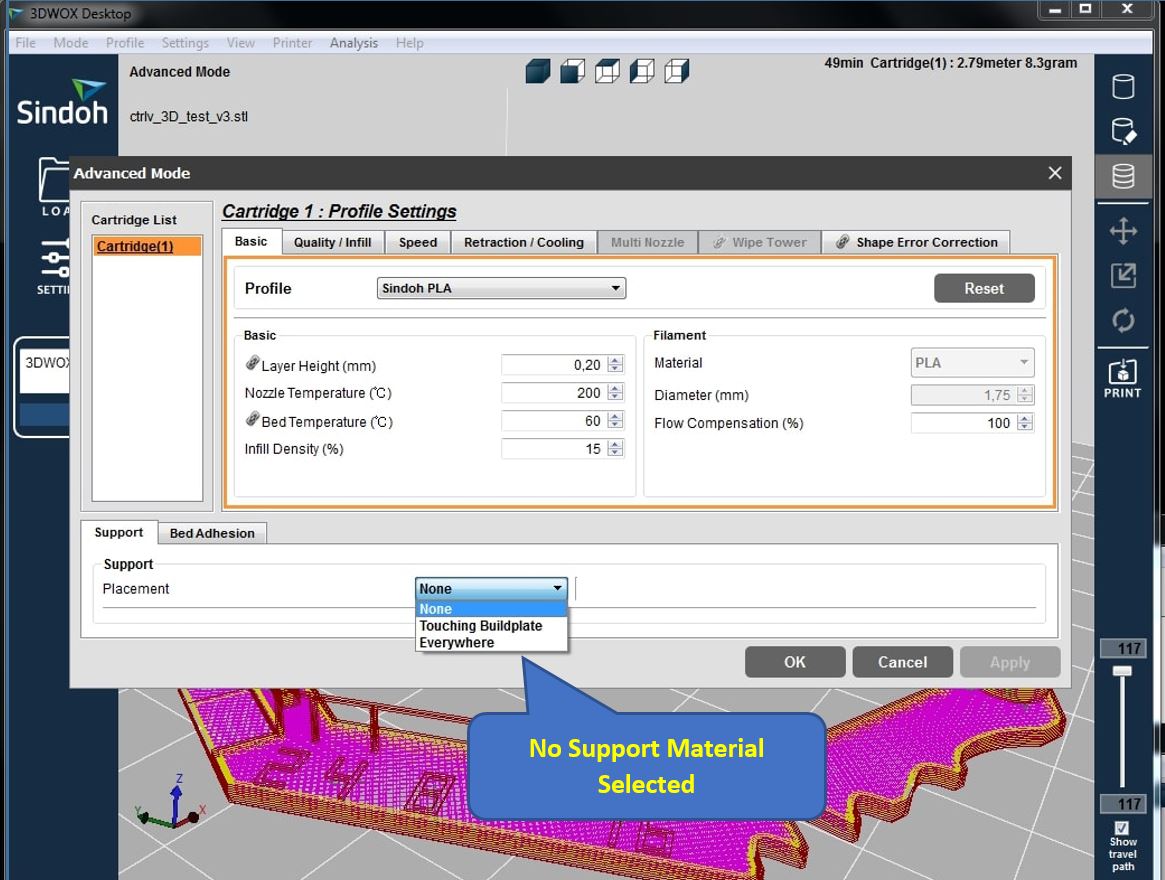
The .stl file format of the model was being opened in the Sindoh 3DWOX software, and the Model can be seen above. The next step was to slice the design into layers, as explained earlier why layering is important. Then was to define whether we require support material or not, for this purpose goto Profile-->Profile Settings-->Support and select None. As, In our case No Support Material was being required and then the command to print the model was given.
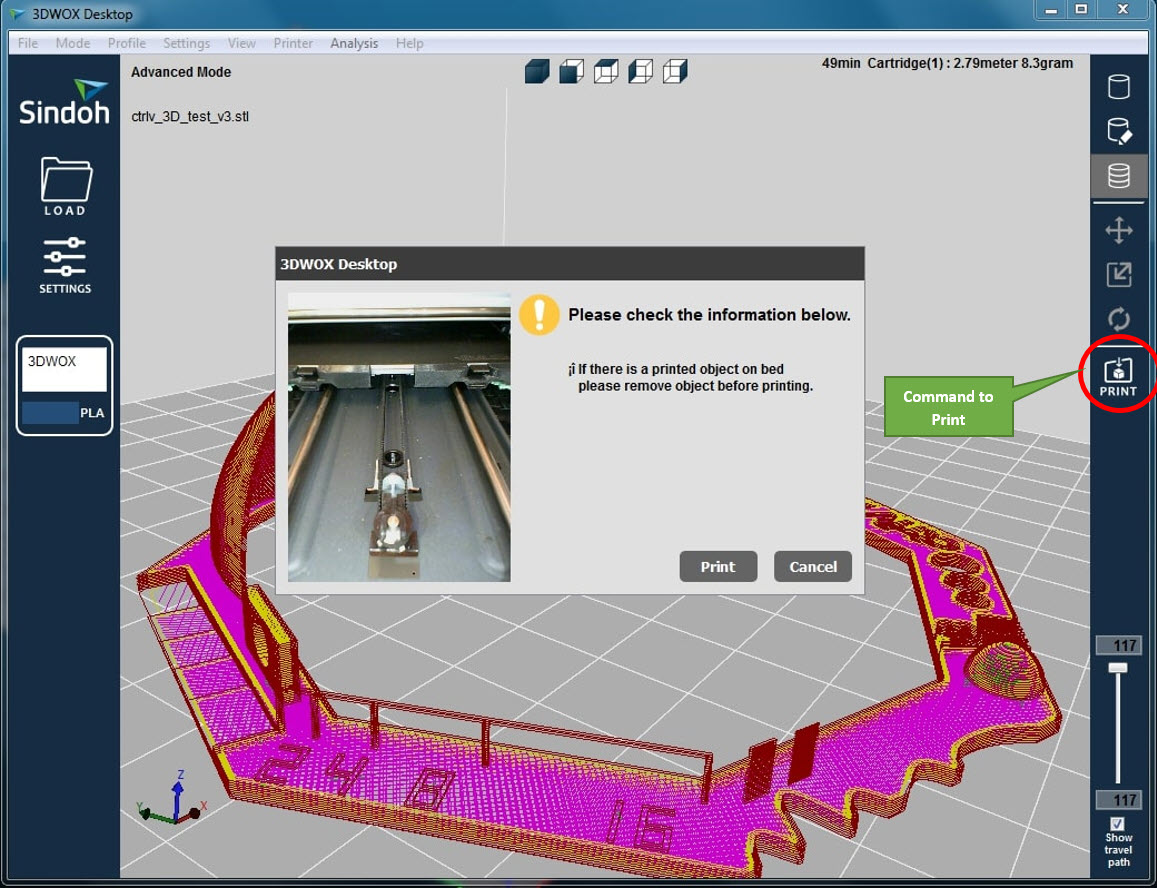
The Print command was given as seen in the below pictue. Take caution, if there is already a printed object on the bed. Do make sure remove that object before having a new print.
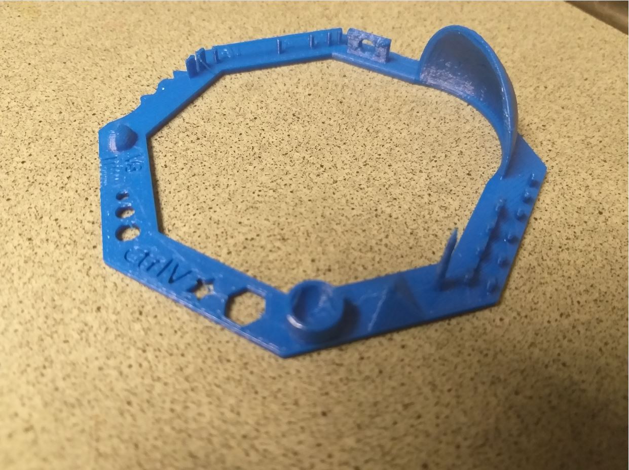
The design was being printed, and it looked really nice as can be seen in the picture above.
Group Task : Comparison
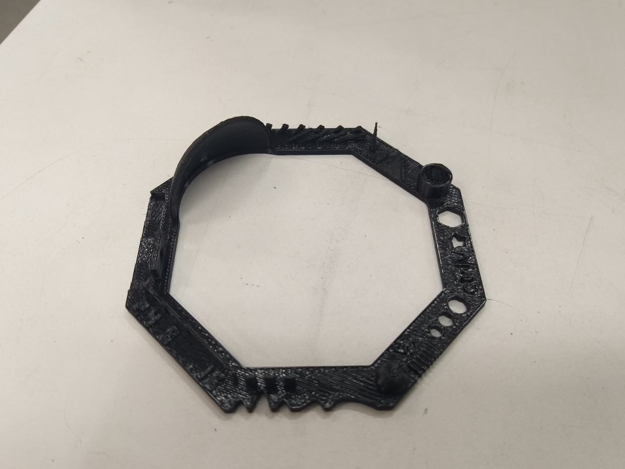
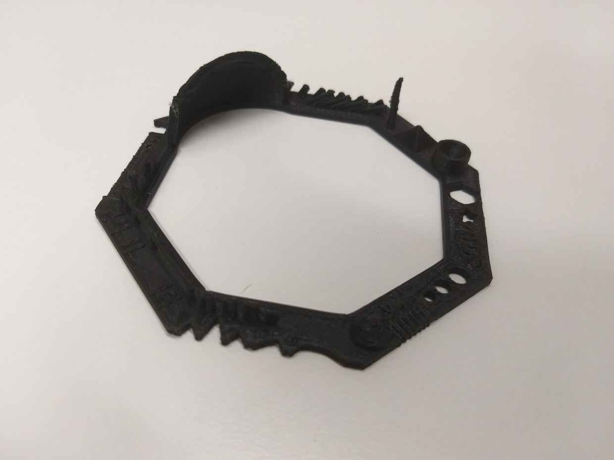
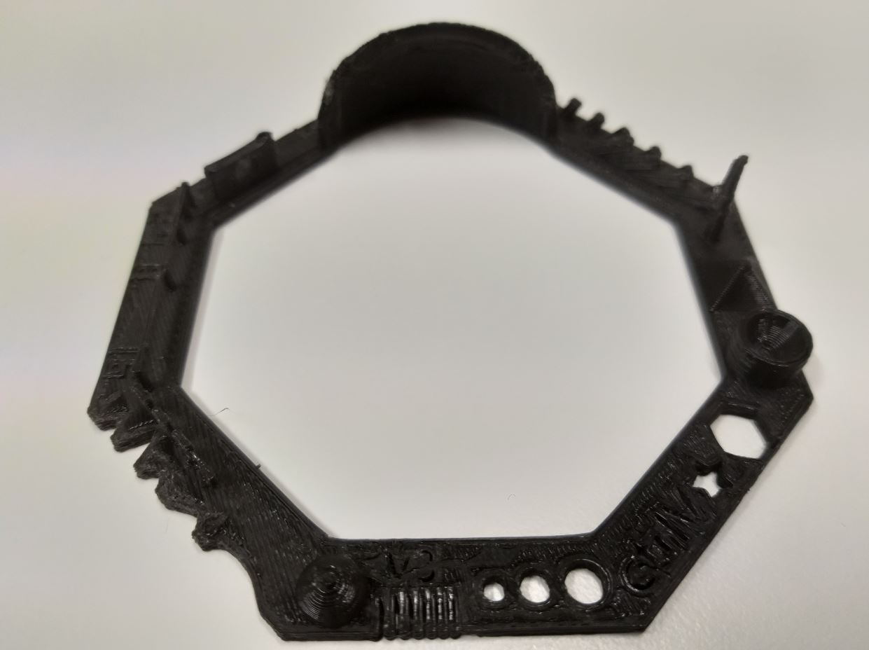
After printing the same model with the three printers, we decided to compare the performance of these three printers. Since the model contains different shapes, Text and tower like stuructures thereby it was a good idea to compare these three printers in order to know the which printer performs best. The Below figure represents the Comparison
Also to compare the tolerances of these printers. By looking at the comb structure of these printers, for Stratasys Fortus 380MC 3D and Sindoh 3D VOX, only 0.6, 0.7 and 0.8 mm from right side are open, the rest are fused together. For Leapfrog 3D, all the combs are fused together. Therefore As per Comparison of all the features, We found that Stratasys Fortus 380MC 3D and Sindoh 3D VOX performed well as compared to the LeapFrog 3D in terms of print quality. On Comparison it was found that Stratasys Fortus 380MC 3D performed better if there are very small circles, comb like structures (tolerances), Inclined planes, Hollow Cylinder shape and a Dome shaped design. Therefore I planned to select this printer for my next Individual Task. The Second best printer that was able to make smallest possible and clear 3D designs was the Sindoh 3D VOX. But I would still prefer Stratasys Fortus 380MC 3D since others printers requires constant supervision and look after when the printing is in progress but Stratasys Fortus 380MC 3D can be left unsupervised.
Individual Task
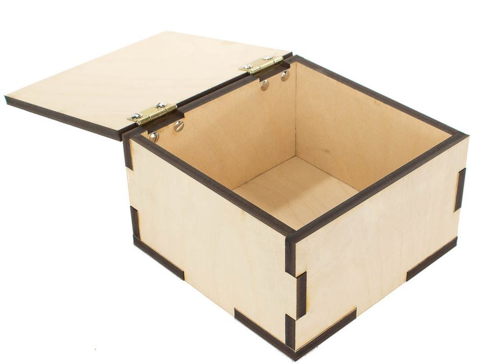
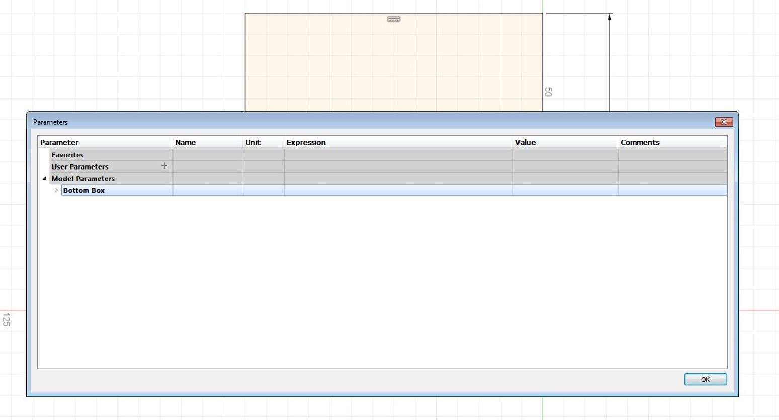
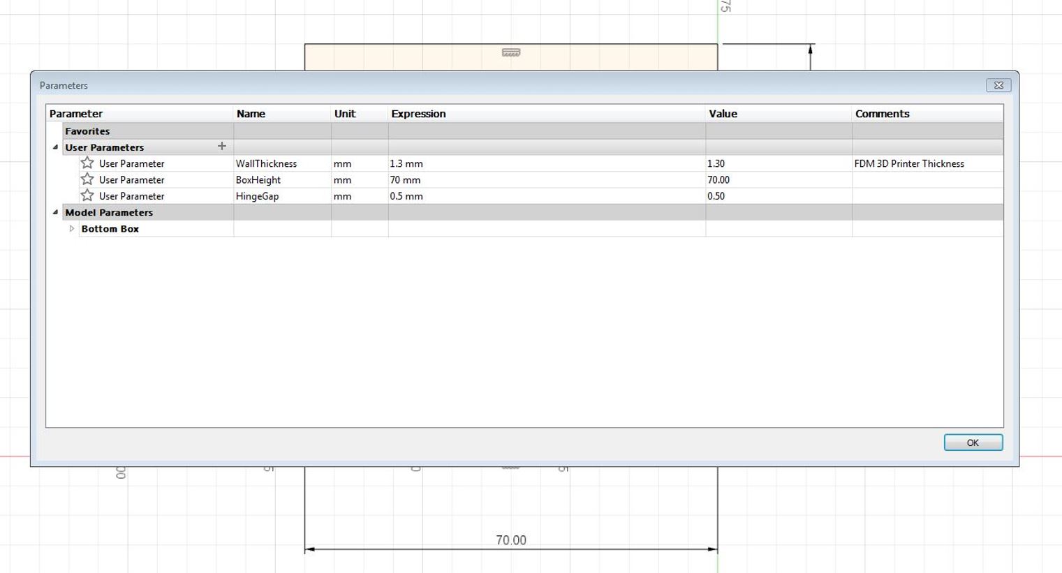
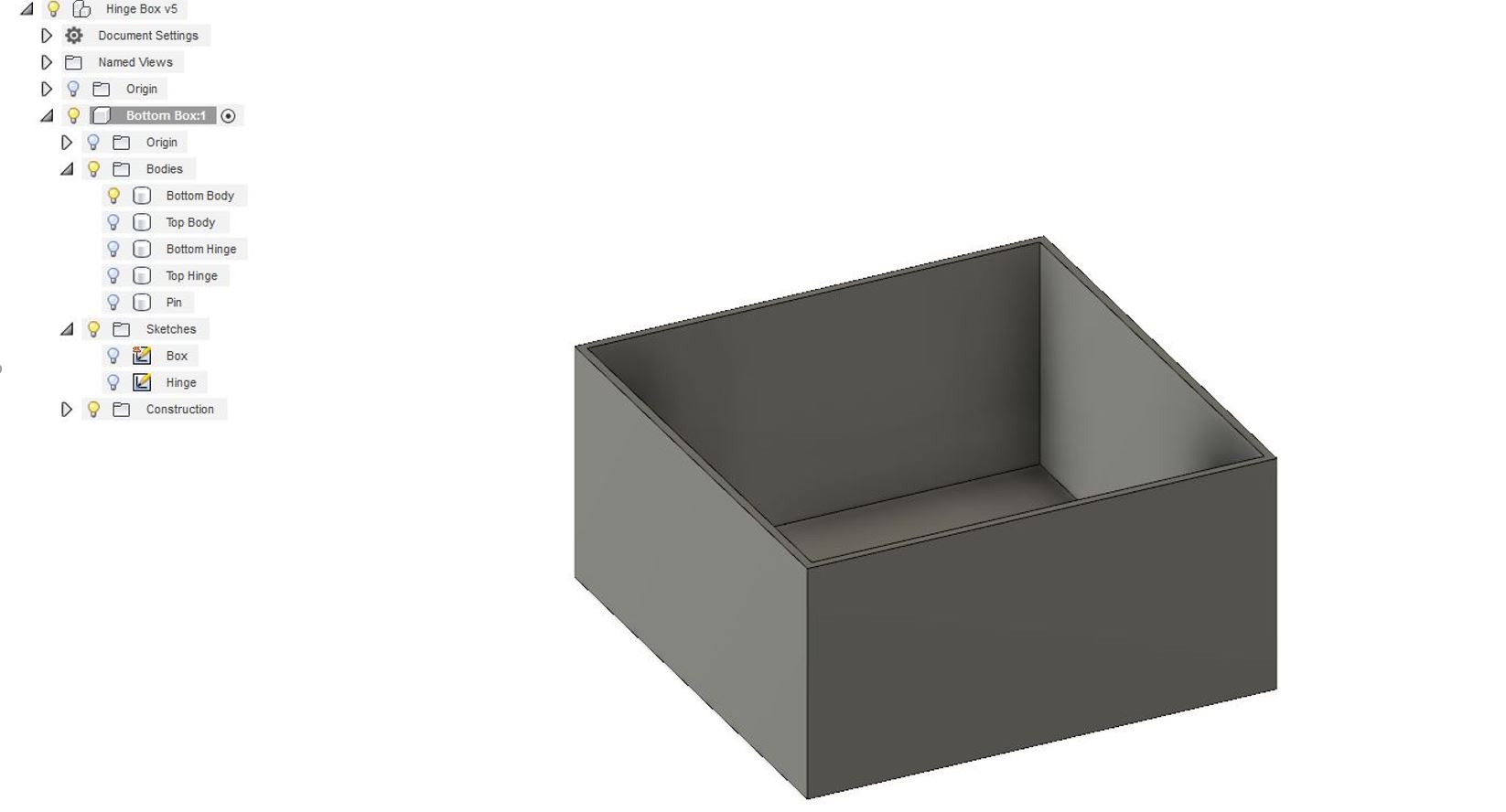
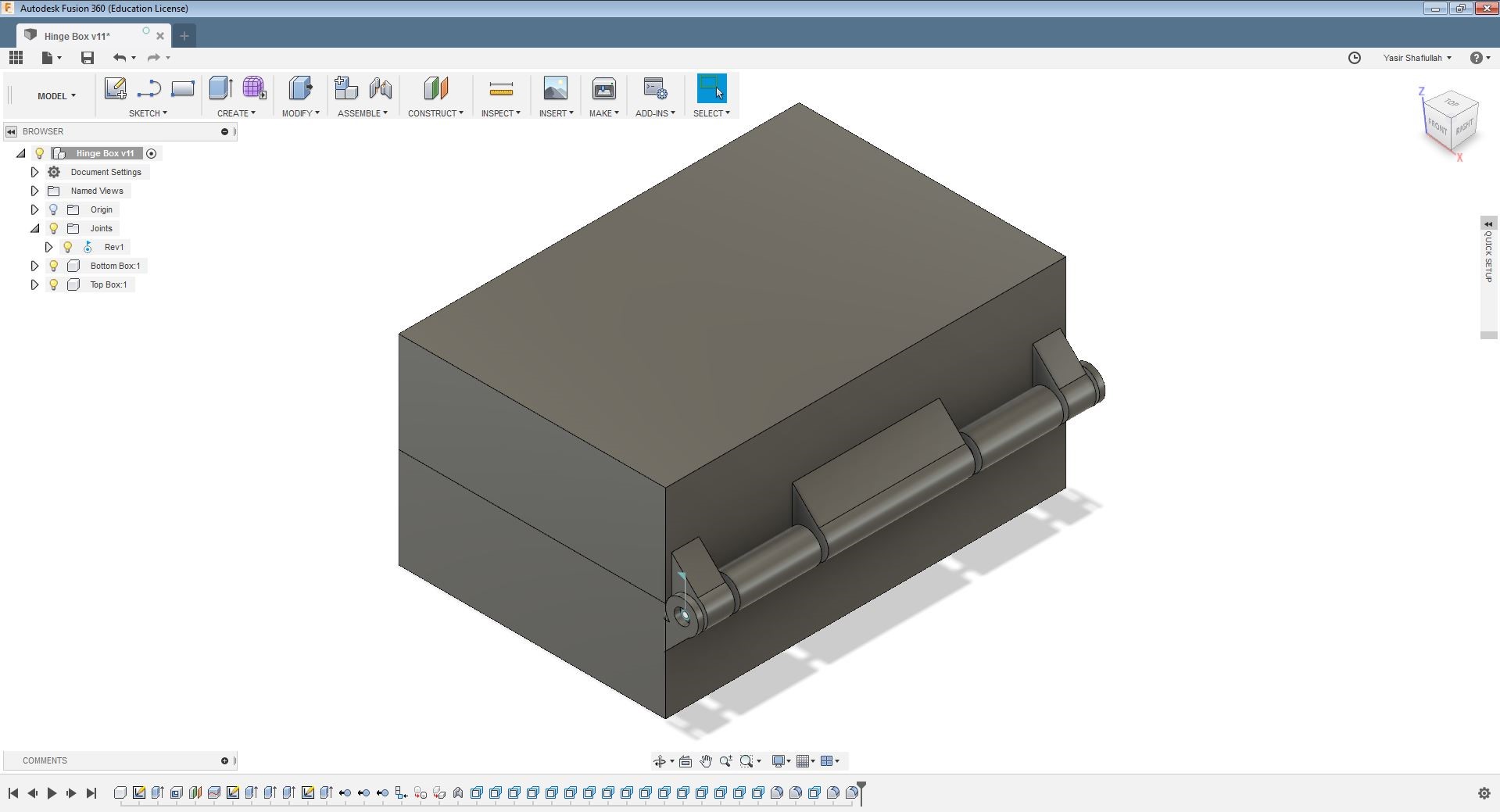
For this week, there are certain rules for the design of the object. It must be so that it could not be made substractively. My design consists in a Hinge box. The Hinge is a movable part at the hinge of the box. It means that the box can be opened and closed by moving that.
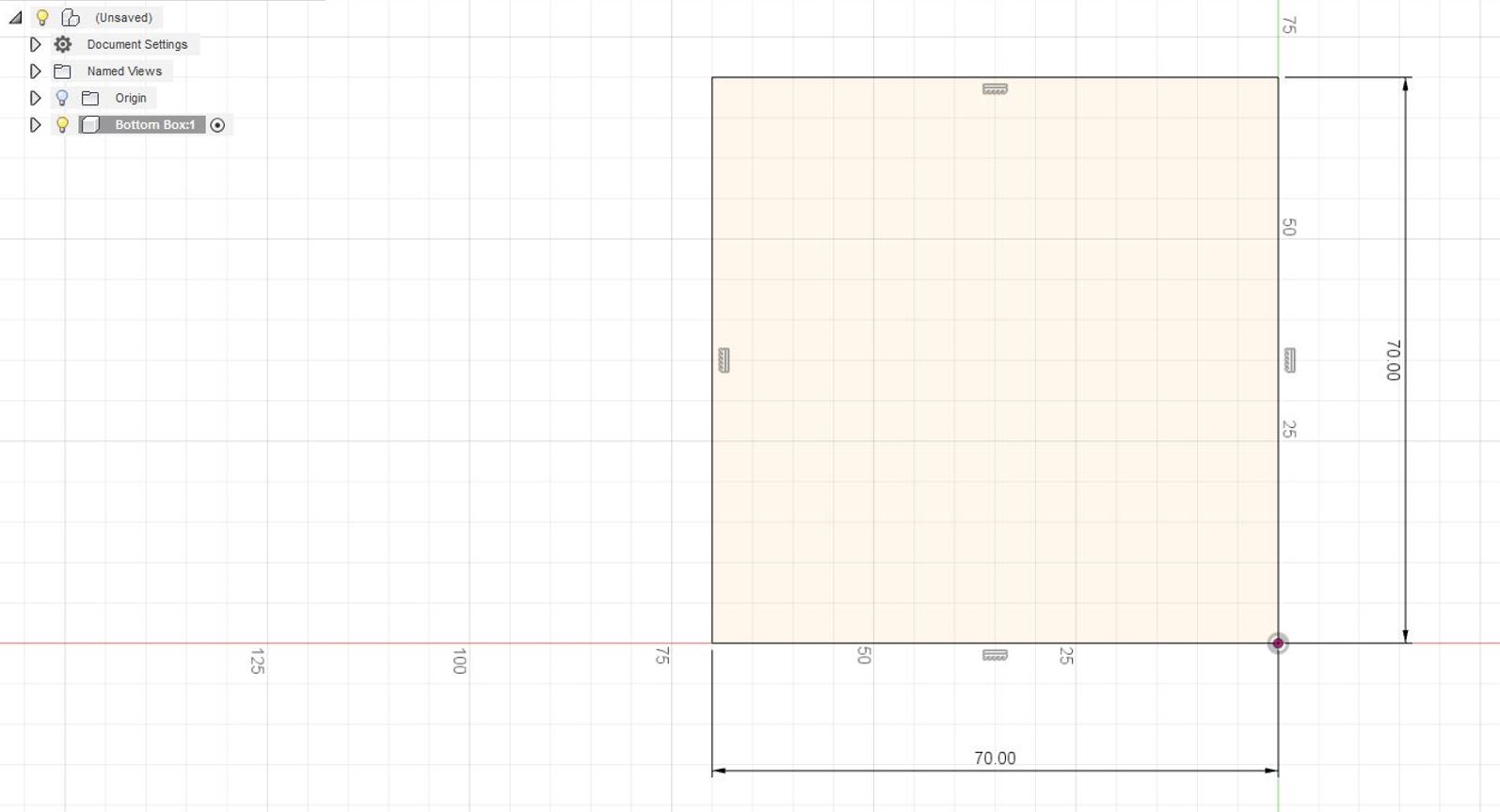
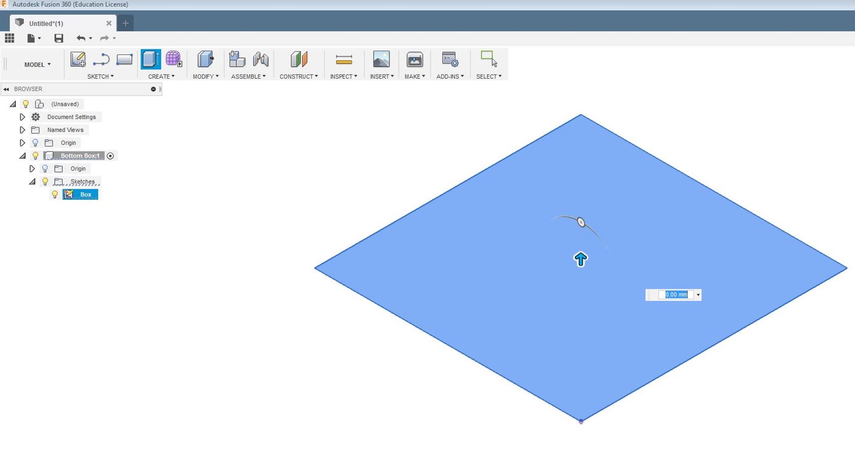
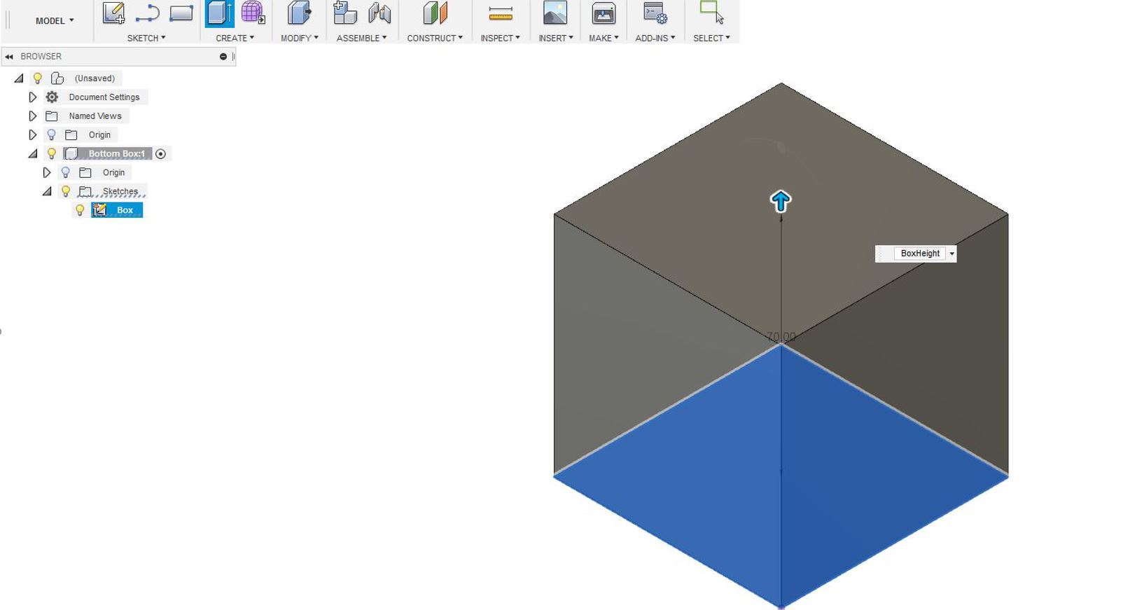
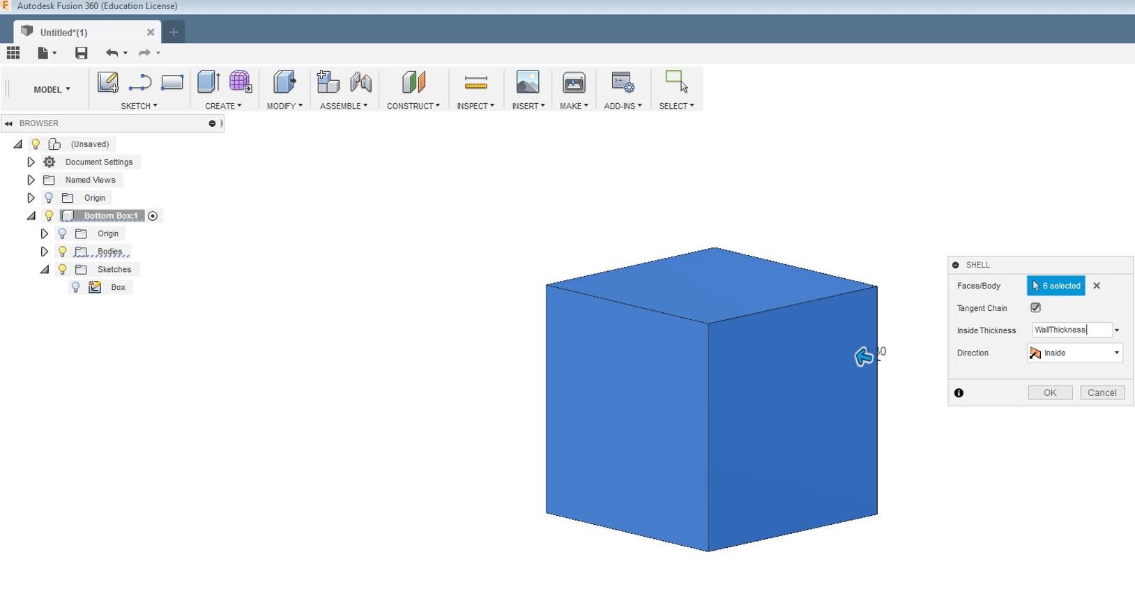
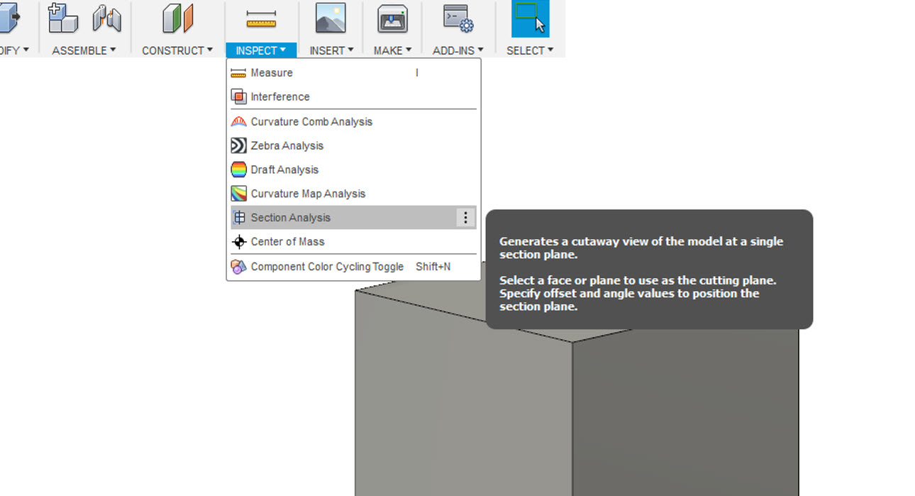
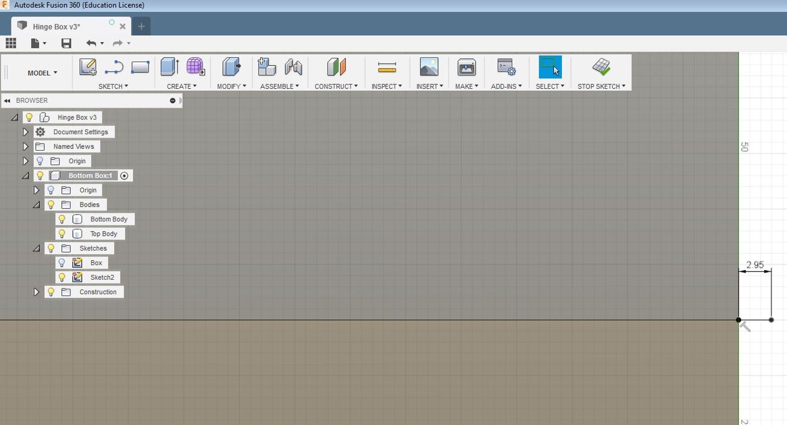
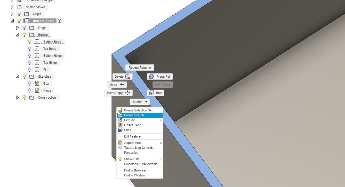
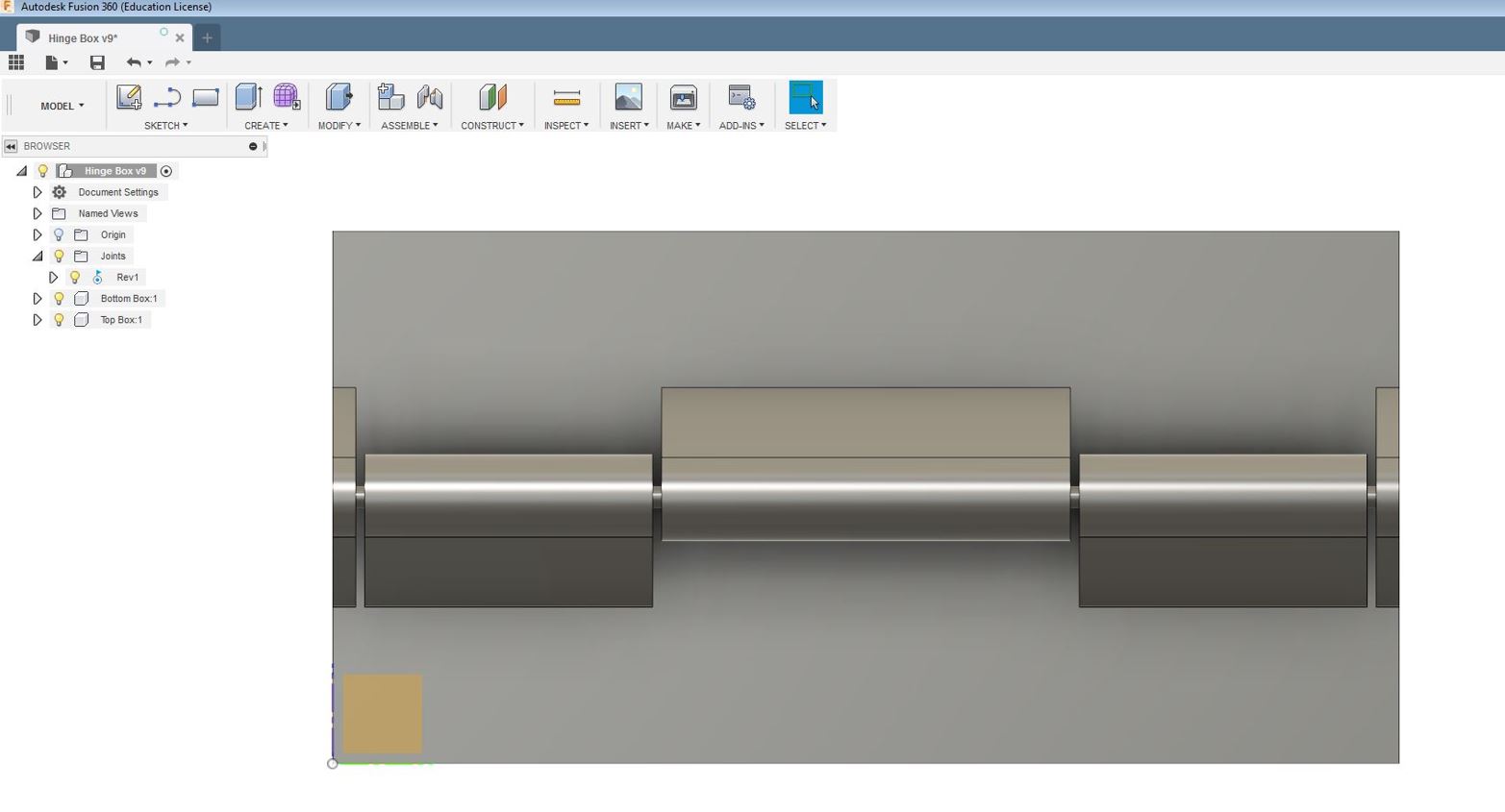
After Getting the idea of my design with a simple square shape, I utilized the keyboard shorcut "R" for this purpose. At every stage of my design, I started to define parameters that will assist me to modify (increase/decrease) the size of the design in the later stages of my design. By looking at the tolerances, I decided to use a hinge gap of 0.6mm for my design with Stratasys Fortus 380MC 3D. My idea was to initially make a simple box and I extruded the shape in 3D thereby I was able to create a box. I modified the box to shell to make the box hollow from inside then I inspected the box from inside by utilizing Inspect--> Section Analyses.
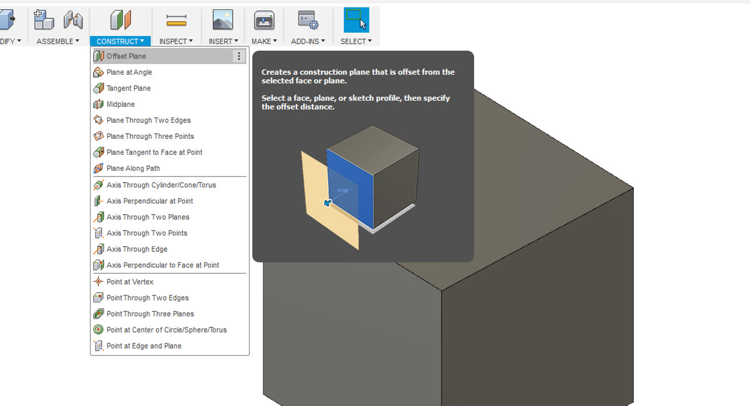
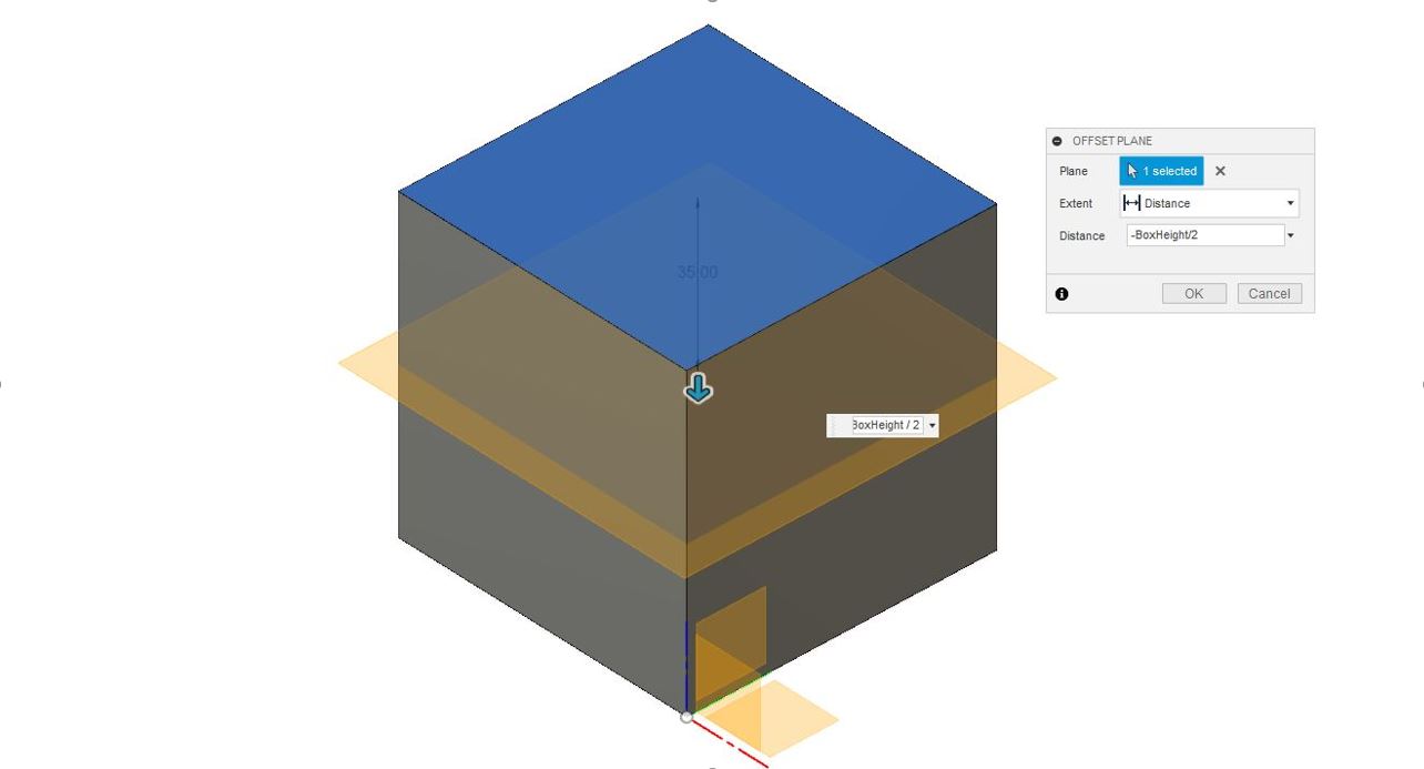
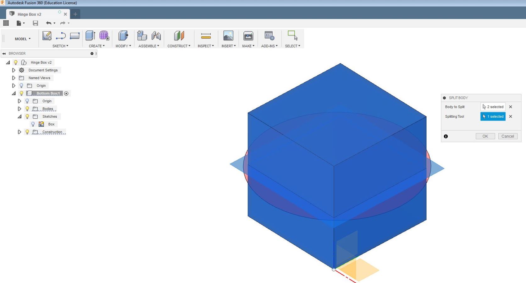
Then, I constructed an offset plane then I Modify-->Split Body and then I splitted the body in halves. As planned the Box was being split in half as seen below in the images as well.
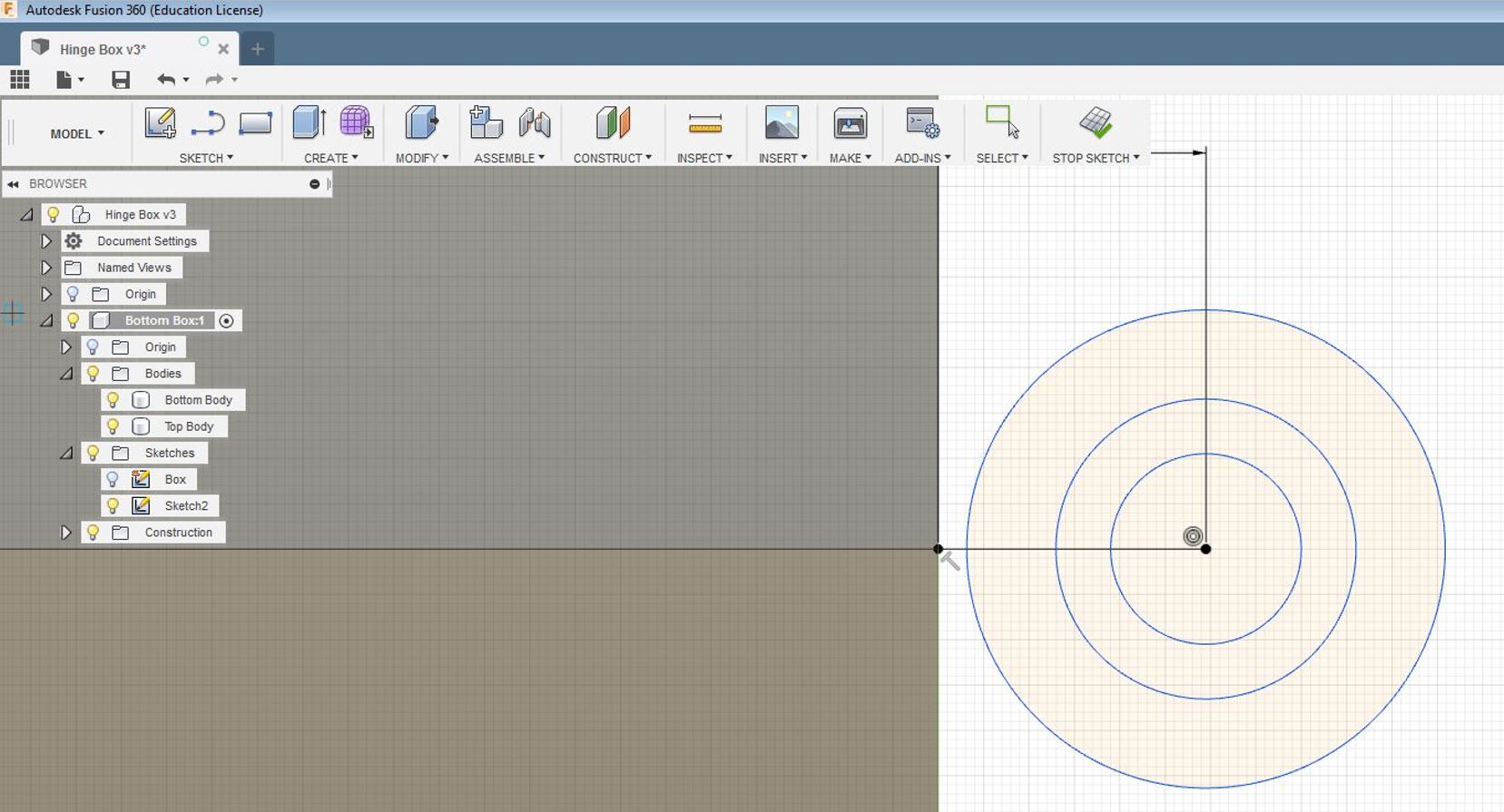
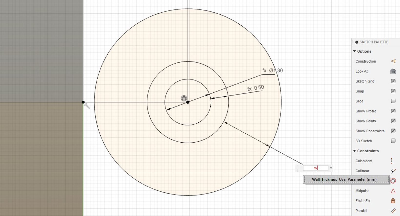
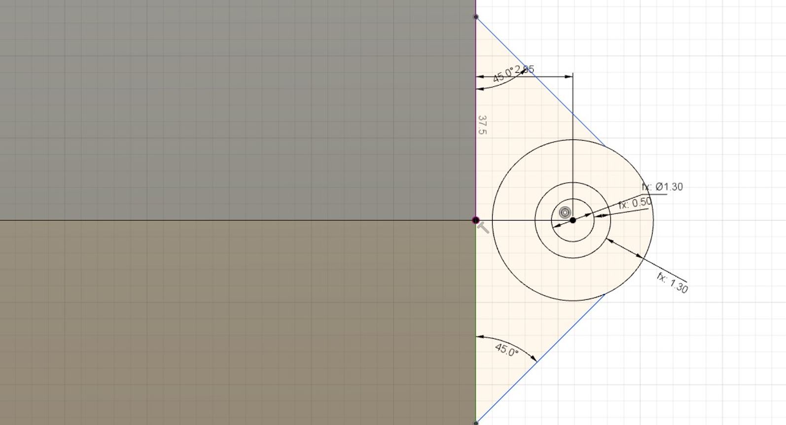
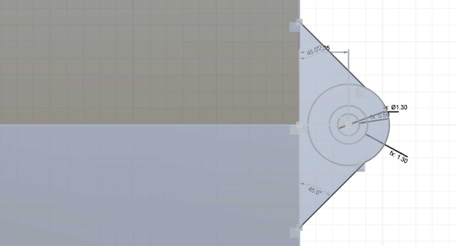
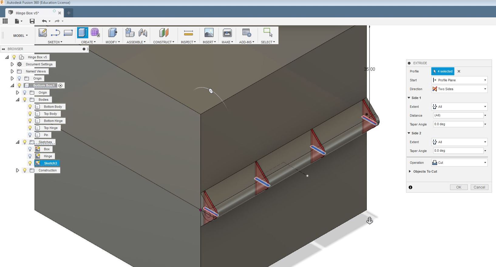
After splitting the box in half, the next step was to create a sketch for the hinge that I was going to utilize for my design. For my Hinge, I required three concentric circles, the 2nd circle will perform the functionality of movement. I seperated these concentric circles with different dimensions "D" in between. To support the hinge with I draw two lines connecting the two split boxes at the edge.
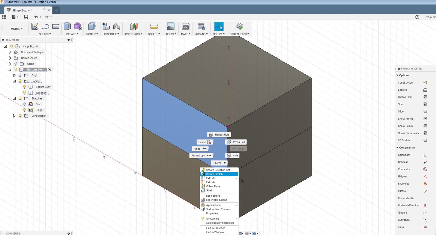
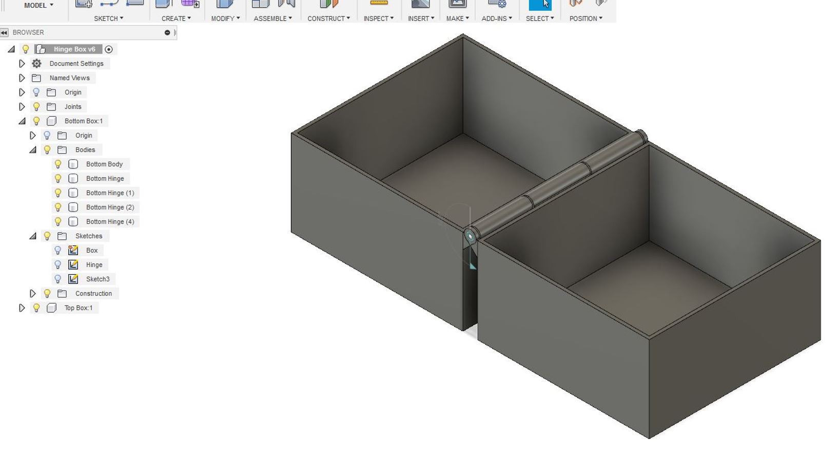
After creating the sketch of the hinge, I extruded the hinge design as seen in the picture below. After that I decided to cut the hinge into three parts, I drew three sketches of rectangle and then I made cutouts of the rectangle slots. I deleted the top and bottom rectangles to create top and bottom hinge at the box.
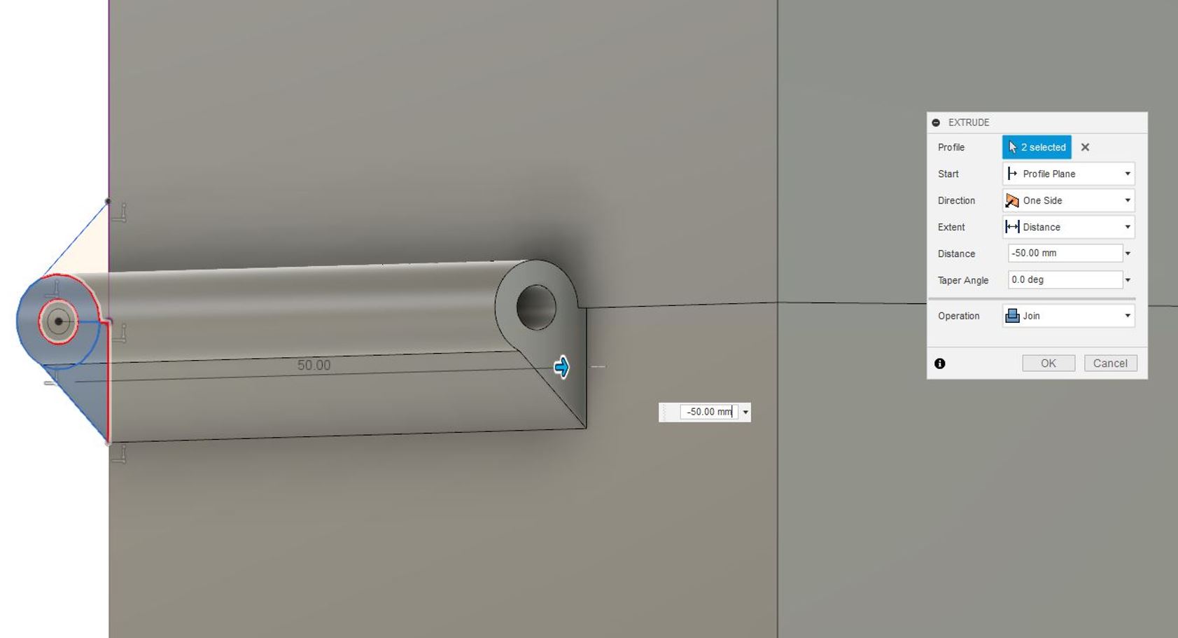
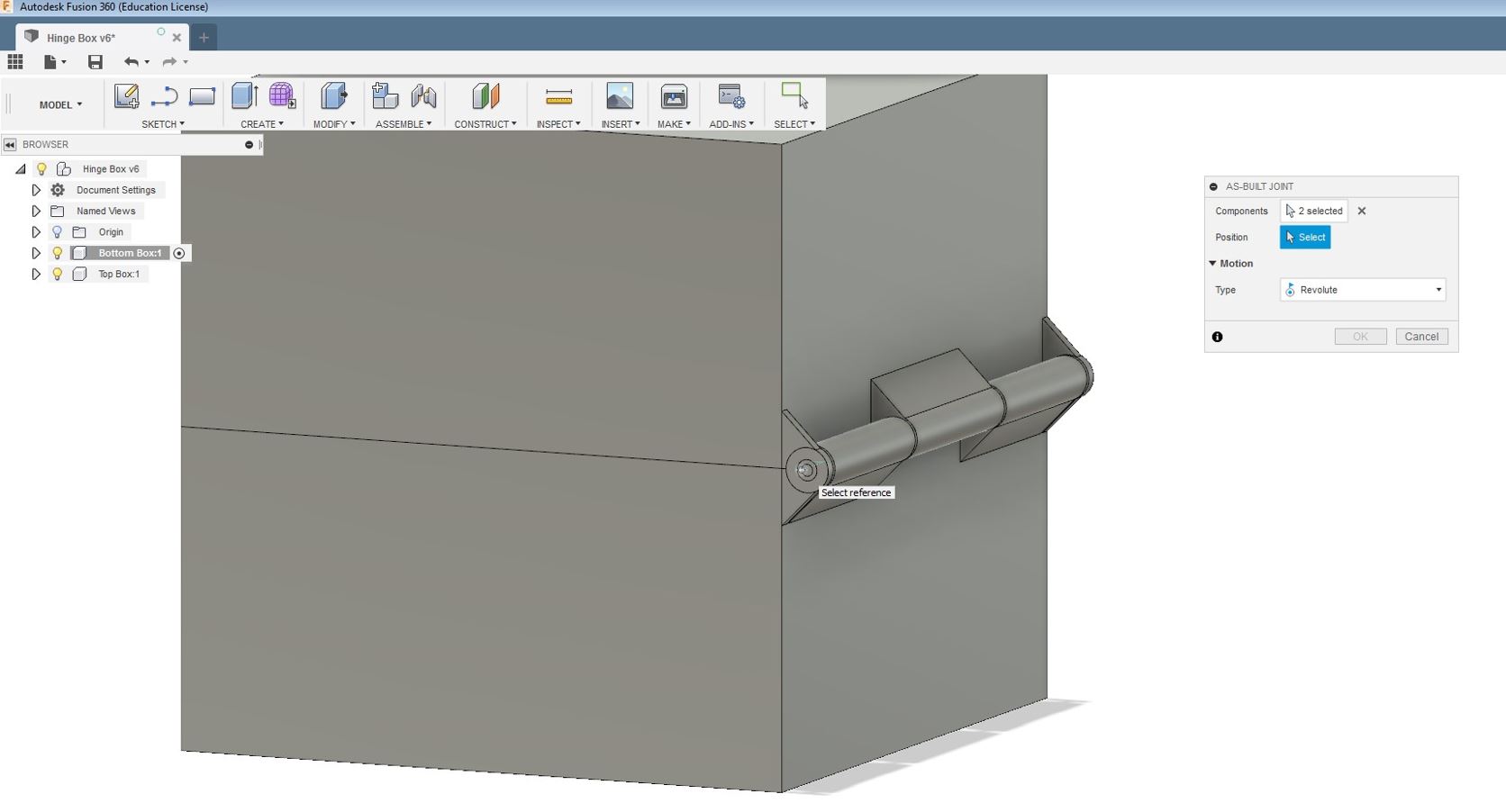
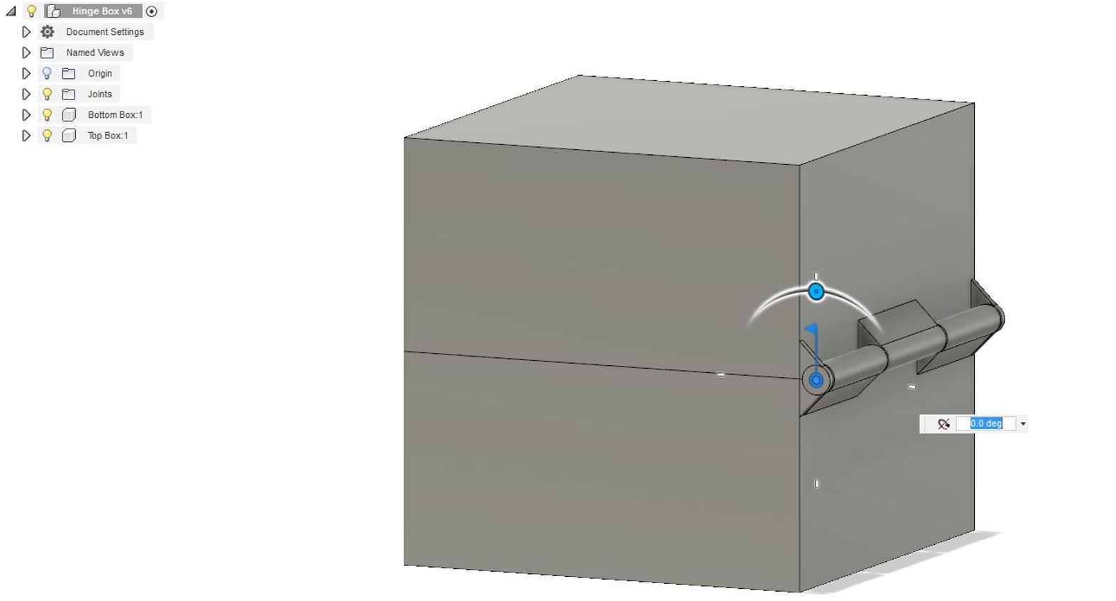
Below picture can be seen with the top and bottom deleted rectangles being deleted. After that to check whether the hinge works, I went to assemble menu and used a build joint to check the mechanism of openning and closing the box. I was able to open and close the box using the assmeble menu. Then I moved to the next stage to print the design using the Stratasys Fortus 380MC 3D
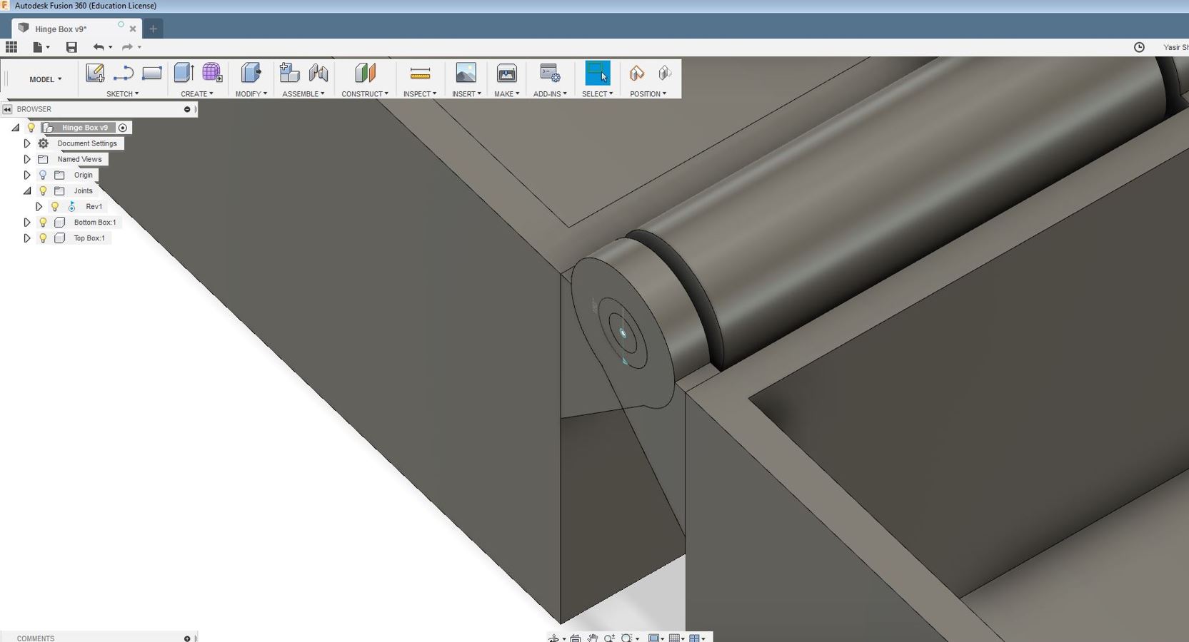
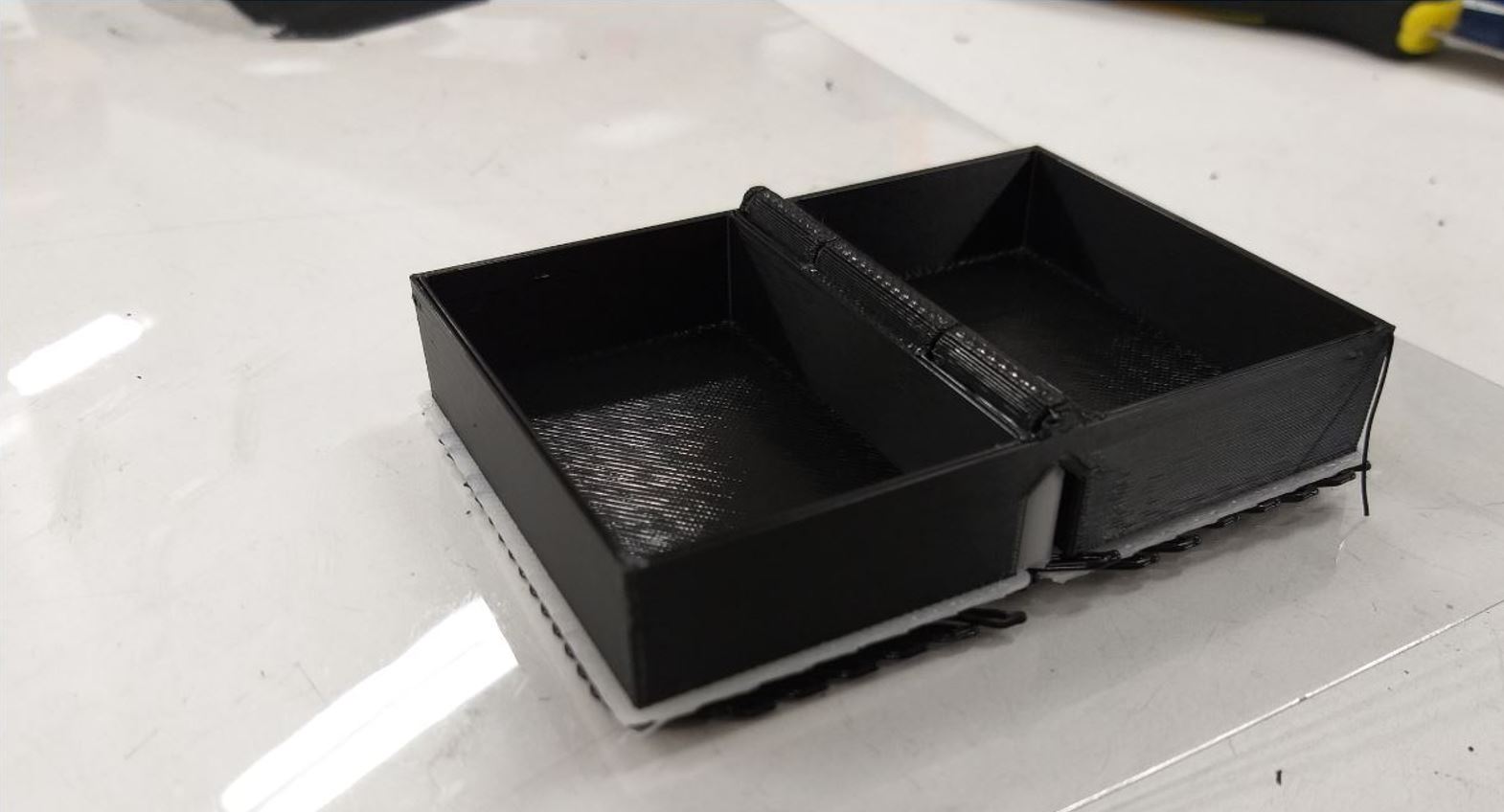
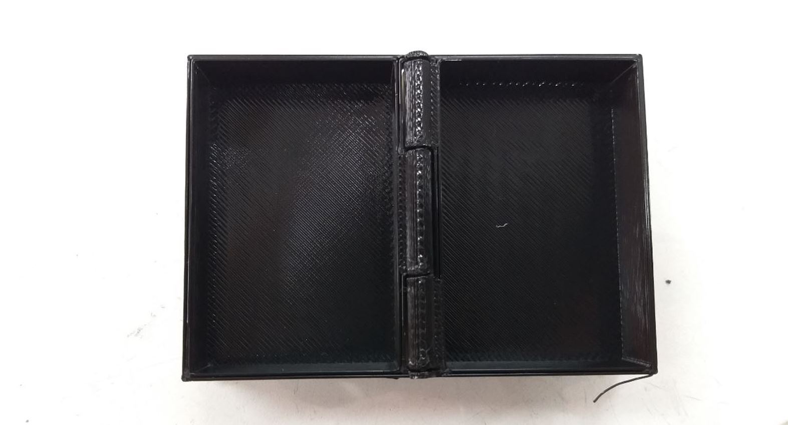
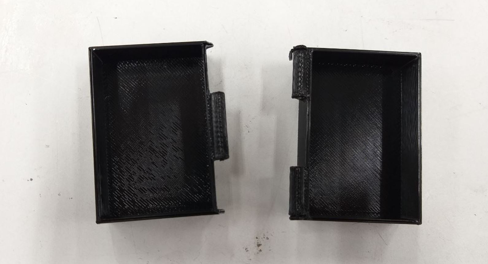
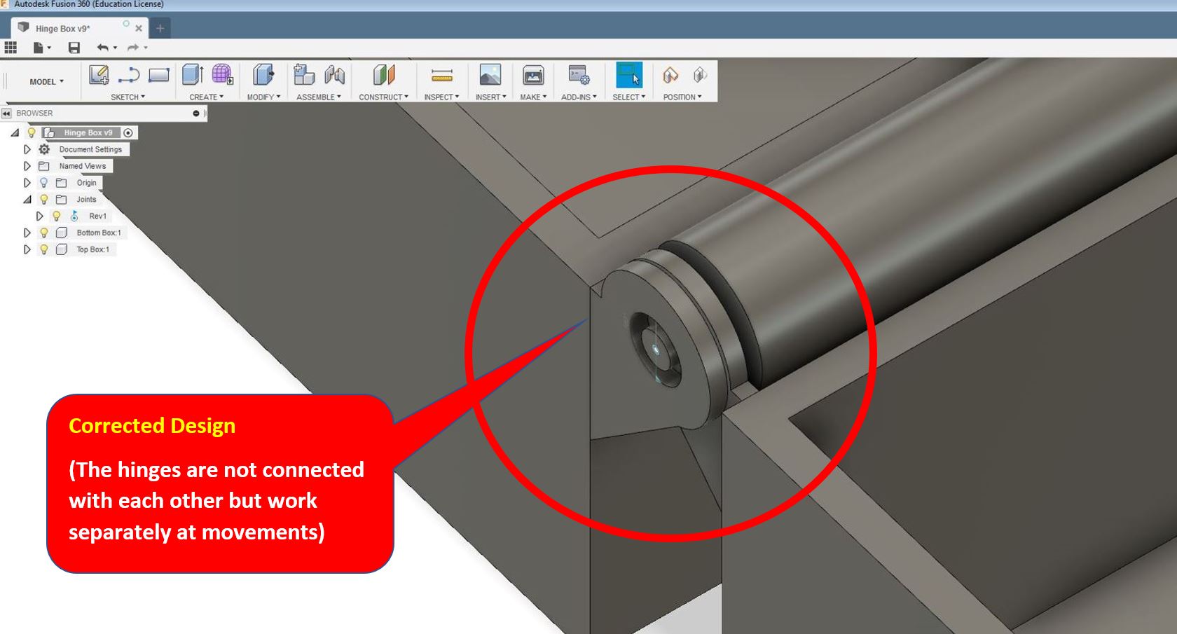
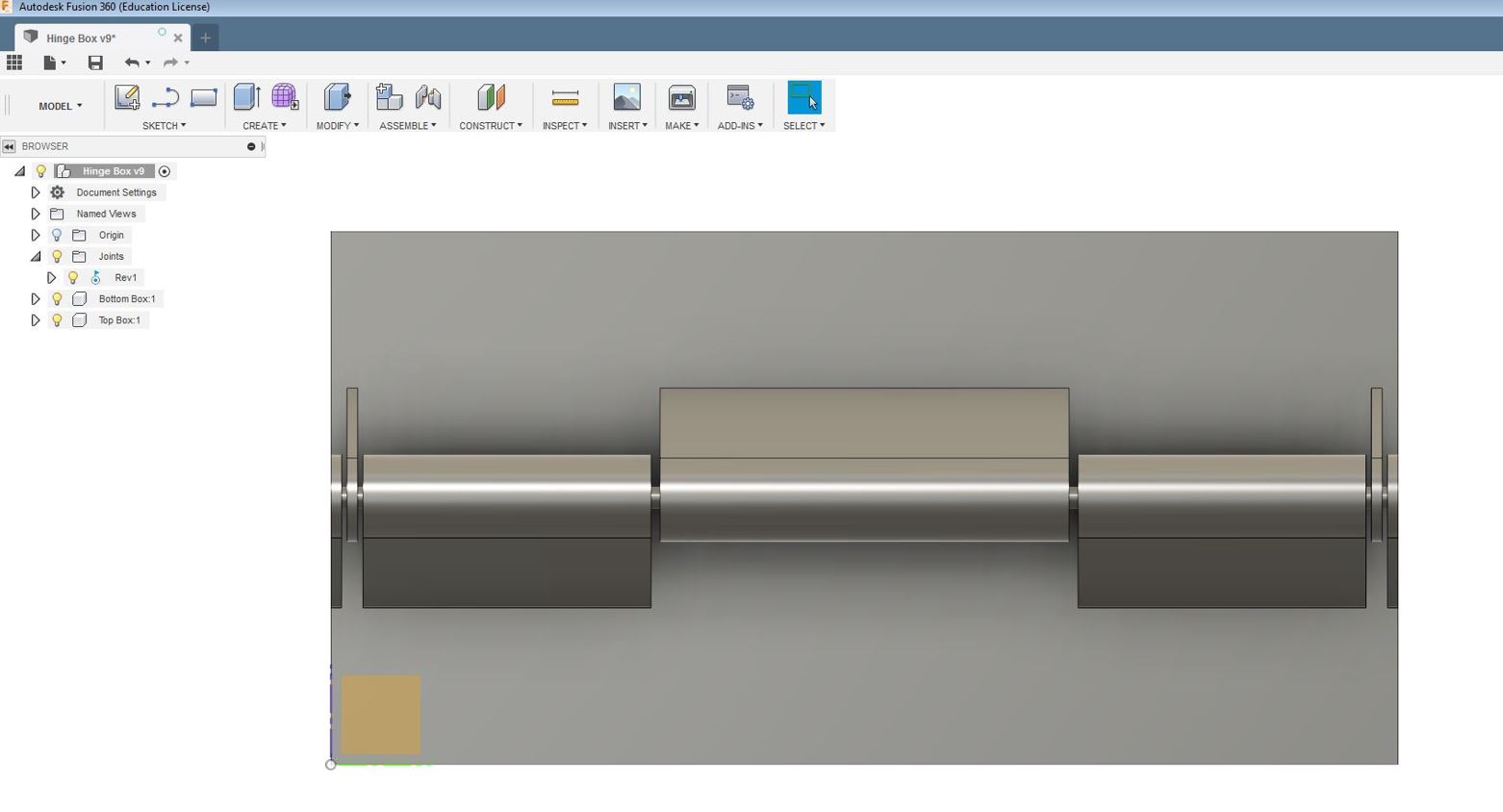
The 3D Printed model broke as seen in the picture above when I was trying to close the box, it seems like the hinge mechanism was not working properly, there was a defect in the design due to which I had to go back to the 3D design of the hinge to see what the problem in the design was. As I looked closely into the design, I observed that the hinges at the edge of the boxes were being connected to each other but actually they should not be connected to create a movable effect. I tried to modify the design by disconnecting the two hinges so that they can perform the function of mobility instead of being connected with each other. Also I modified the width of the hinges as seen below in the cross-sectional images of the hinge. Finally I proceeded for the print again.

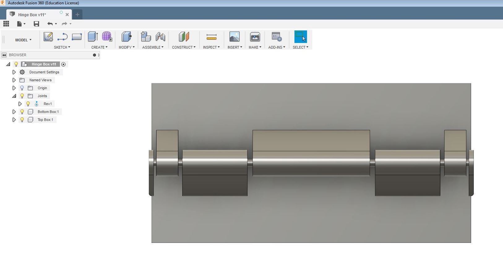
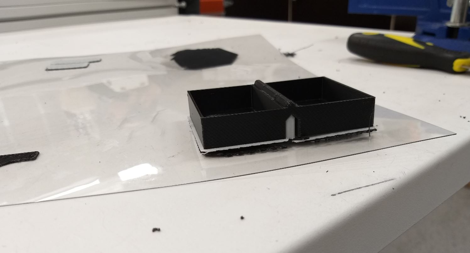
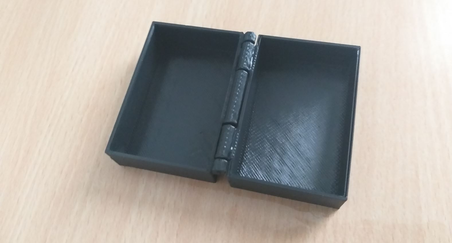
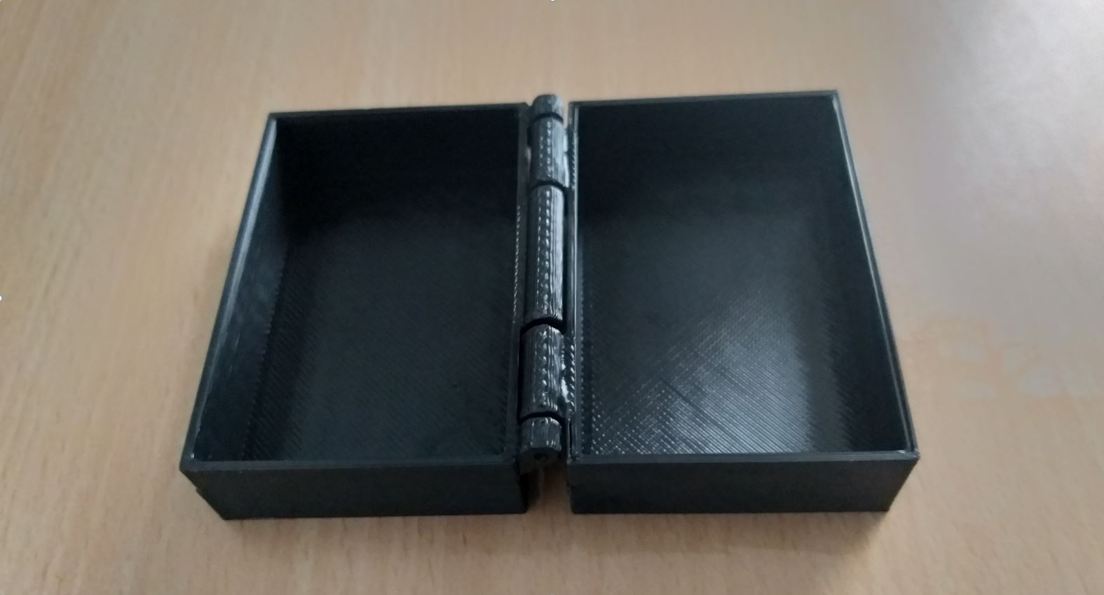
After printing, I check the 3D hinge box mechanism and this time it worked perfectly for me. It was finally a success, the modication in the design also demonstrates this as shown in the video.
The below model was created using Fusion 360:
Hence, the task was concluded. The design works extemely fine although there were few problems in the design but with the modifications in the design, the design works fine now. It is to be noted, the design printed cannot be made subtractively since the It has 2 moving hinges around 1 stationary rod in the mechanism. The Rod in between the hinges is stationary and the two hinges are moving around it thereby it is additive. The spacing between the stationary rod and the hinges from inside is 0.54mm which is very small. Inorder to make it subtractively even at the CNC Machine, the depth of the hinges holes to place the rode inside and spacing cannot be acheived thereby the design cannot be made subtractively.
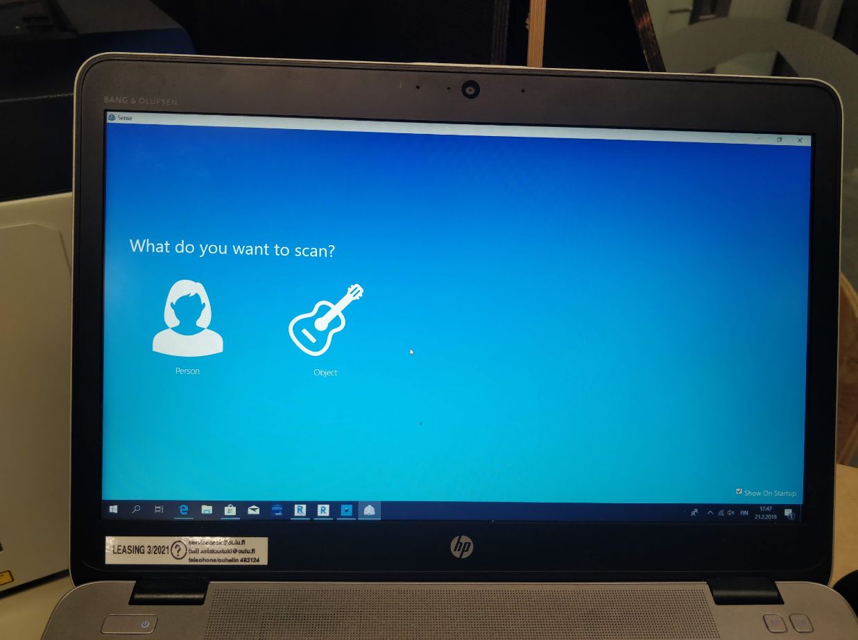
Individual : Scanning Task
Scanning : Sense 3D Scanner
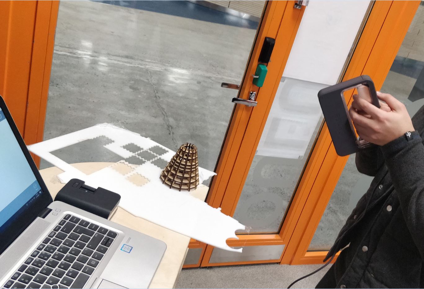
The other Individual Task was reconstruct a 3D object by taking photos of it. So, take several pictures of the object in a certain way, pass them to an special software (in my case Sense Software) and obtain a reconstructed mesh of the object.The Sense 3D Scanner was being utilized for this purpose
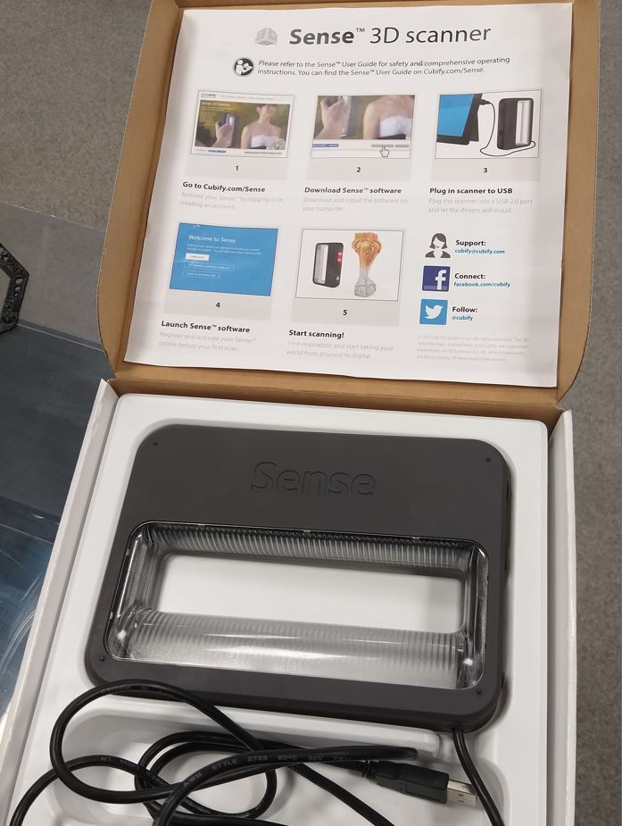
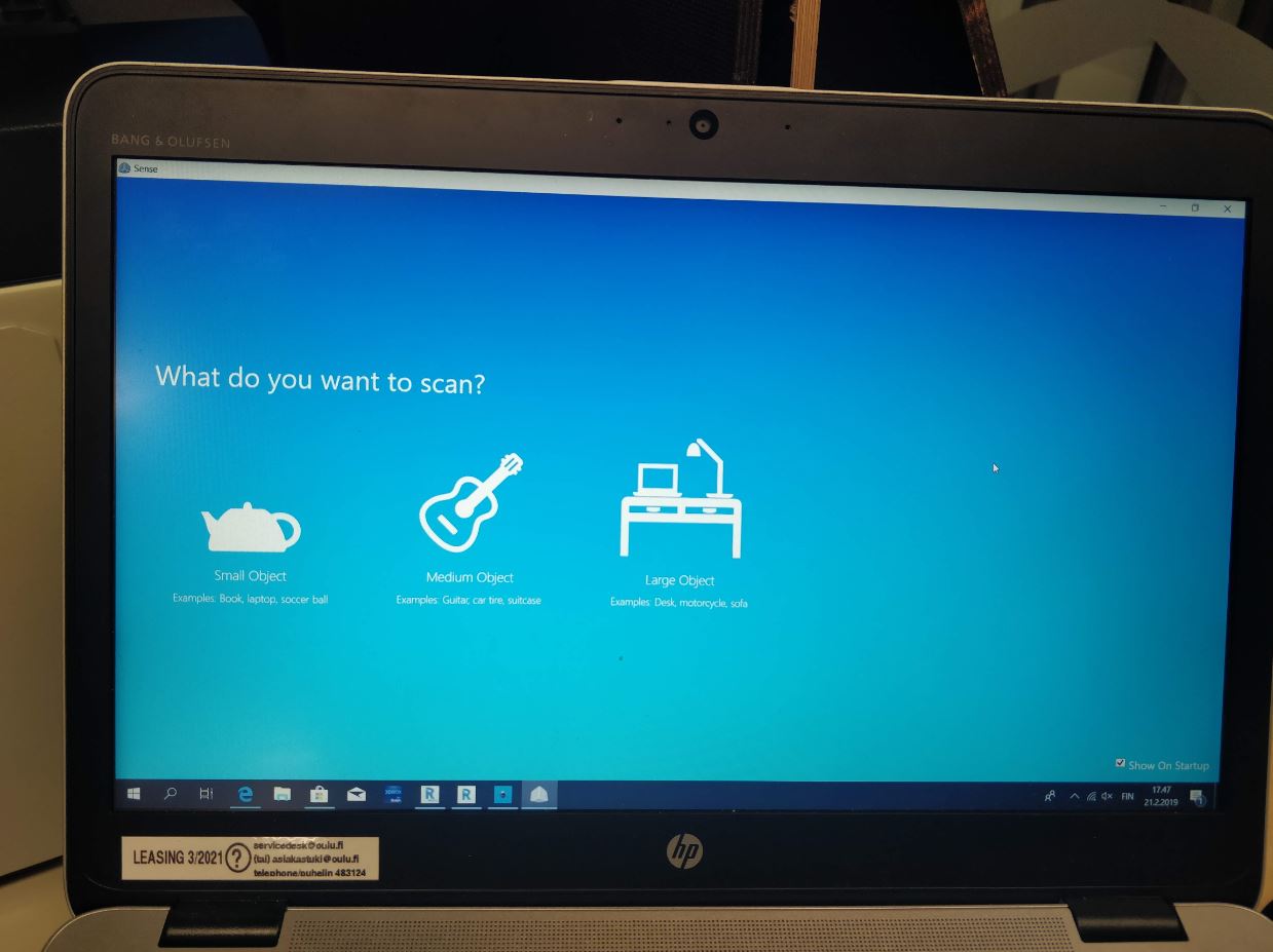
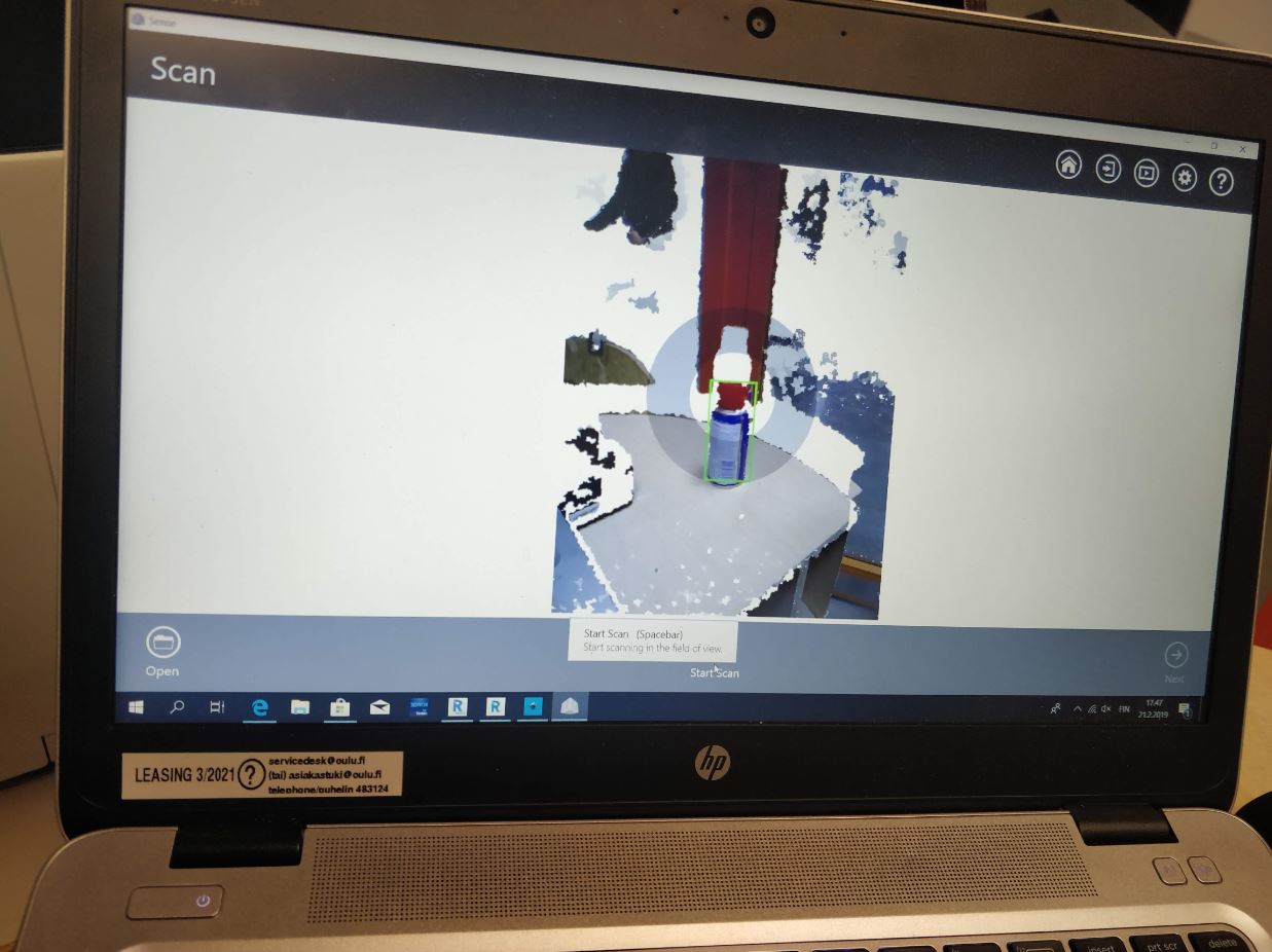
I selected few objects in the FAB Lab for my Scanning process, The Software Sense 3D Scanner is pretty easy to use. The Software has an initially asks for the Type of Object and then it asks about the size of the object which I was willing to scan. place the object stationary on a flat surface and with the 3D Sense device in hand move around the object by placing the center circle as seen in the software of the scanning device onto the image.
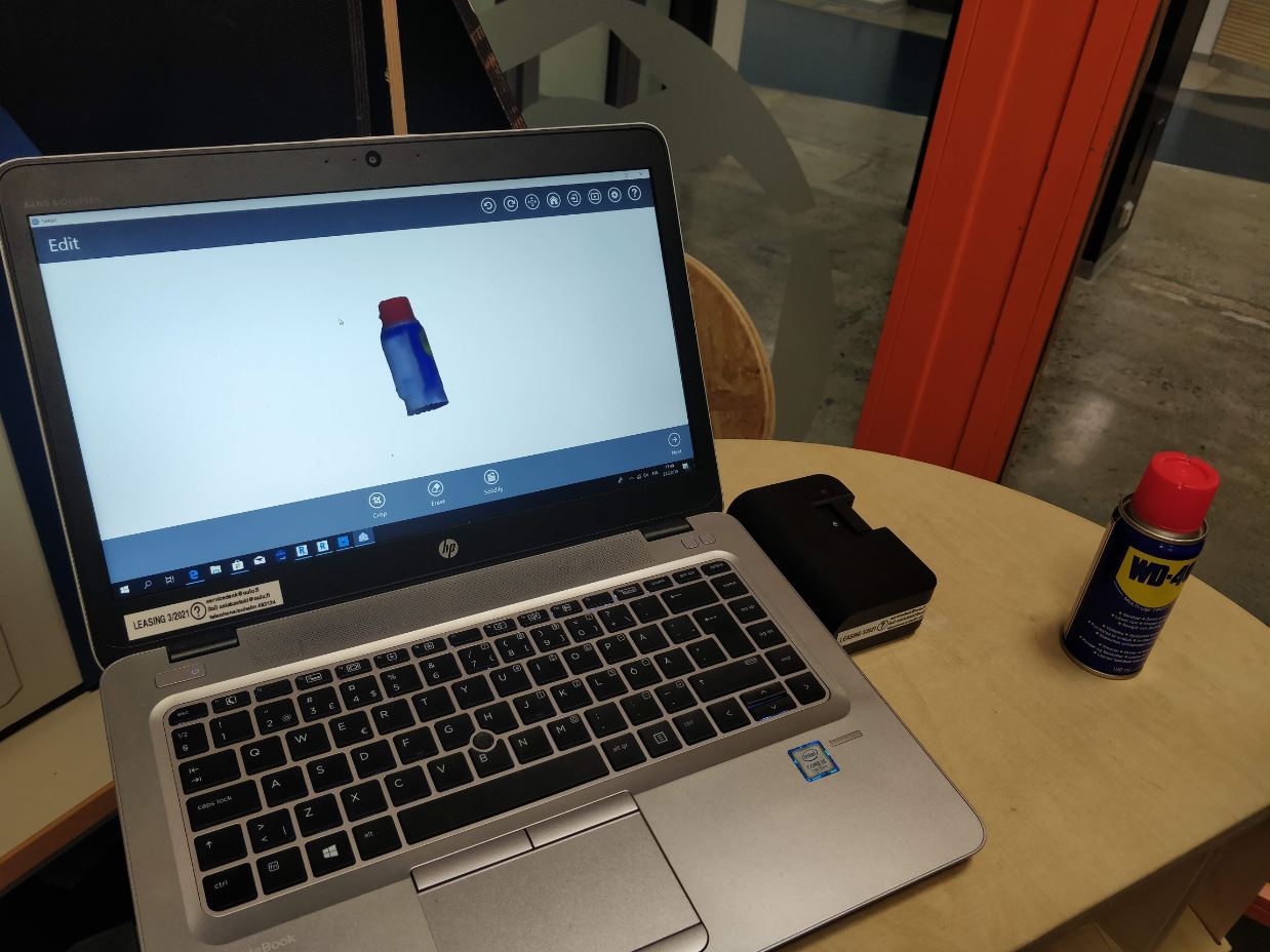
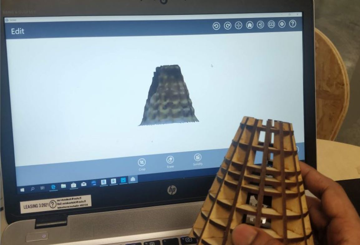
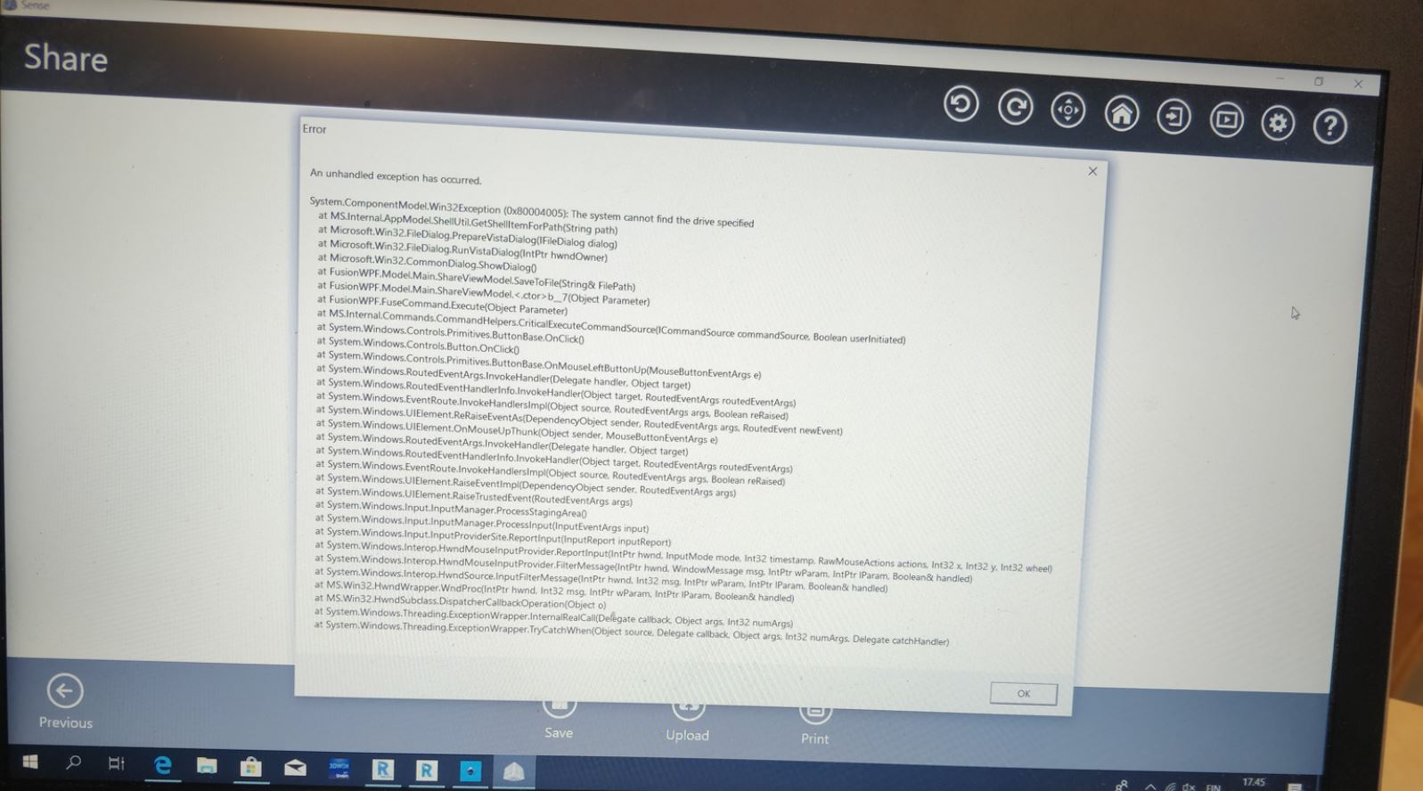
Unfortunately, I was not able to save the objects I scanned as I was facing some errors when saving the 3D scanned objects. The error is due to some limatation of the software to save it on the hardrive. As seen in the pictures as well, the error faced when saving these objects.
Scanning : Autodesk Recap
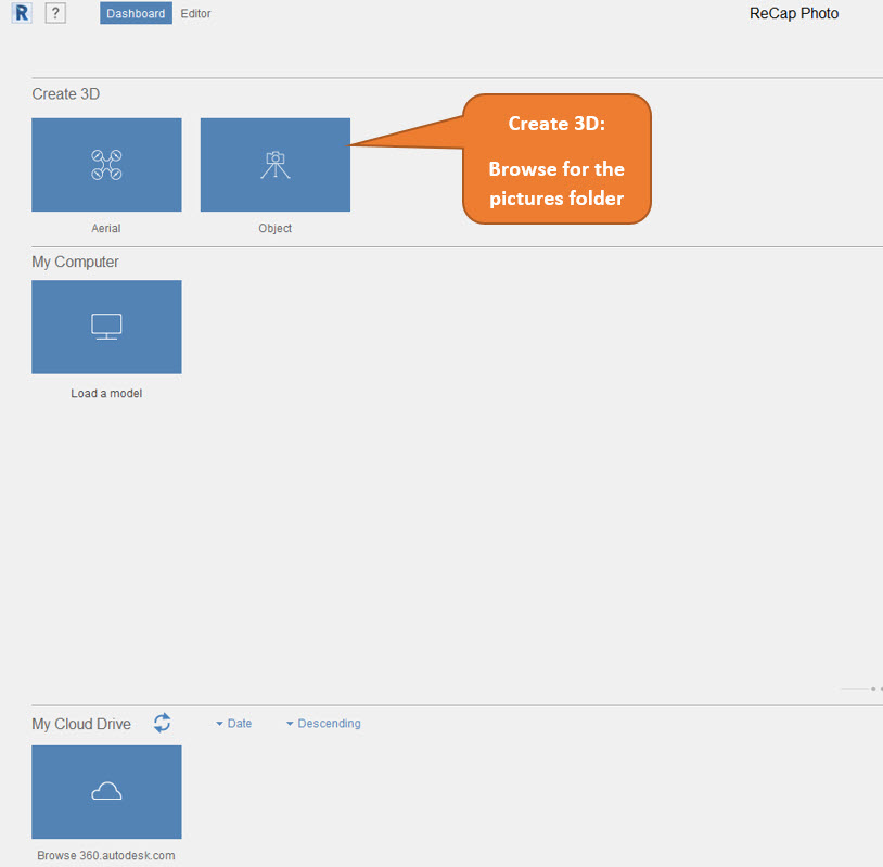
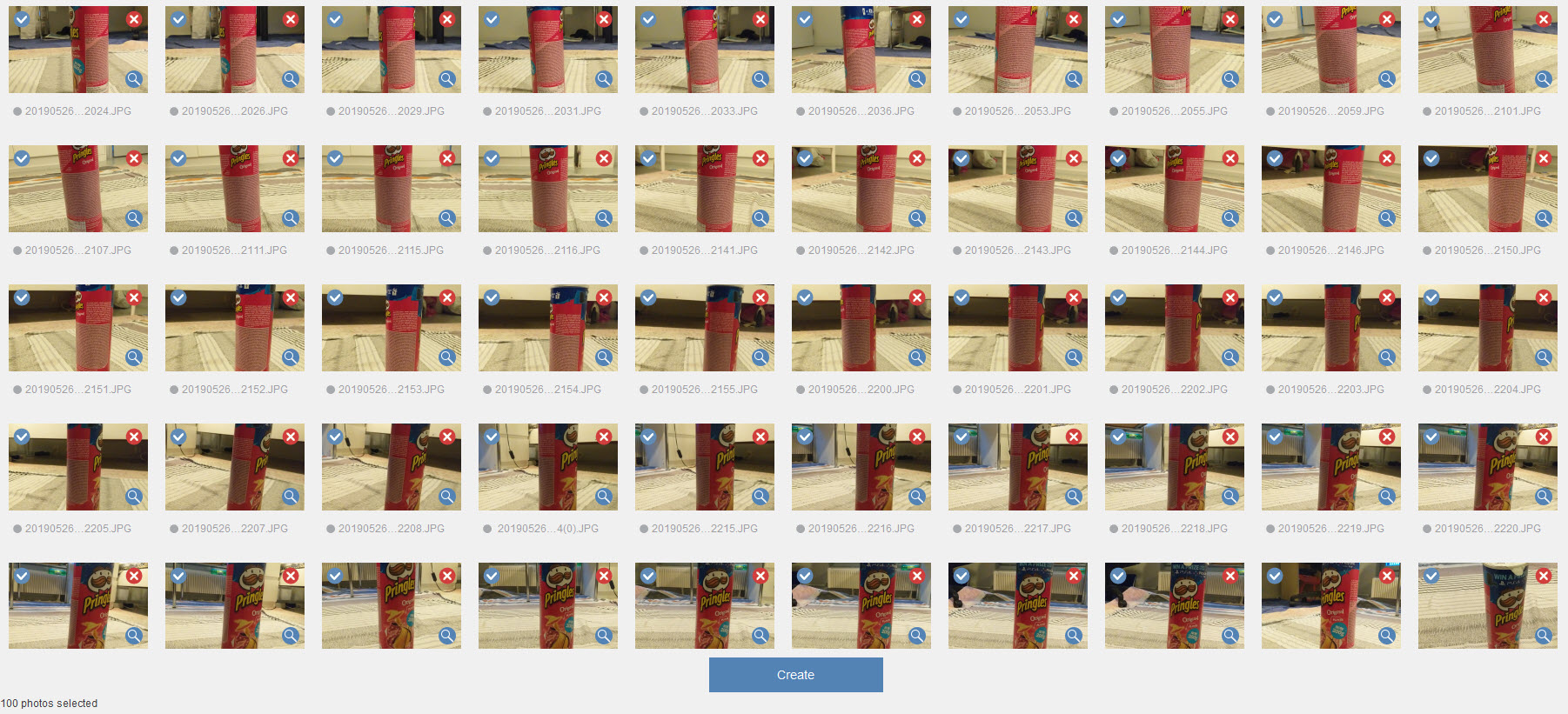
The other software which I tried to use was the Autodesk Recap photo. The Autodesk Recap photo takes a series of pictures as input, The pictures are then uploaded onto the cloud server and a 3D model is being generated. I found this video really helpful inorder to know how to take pictures correctly. The pictures shall be taken in two concentric circles at different angles to cover the complete object. The below picture demonstrates that:
- Below are some Instructions shall be considered while taking the pictures:
- Donot use shiny objects
- Take a Picture every 5 to 10 degrees around the object to two different circles around the object to get a better 3D view.
- Donot use flash since it will create shadows that will vary from one view point to the other.
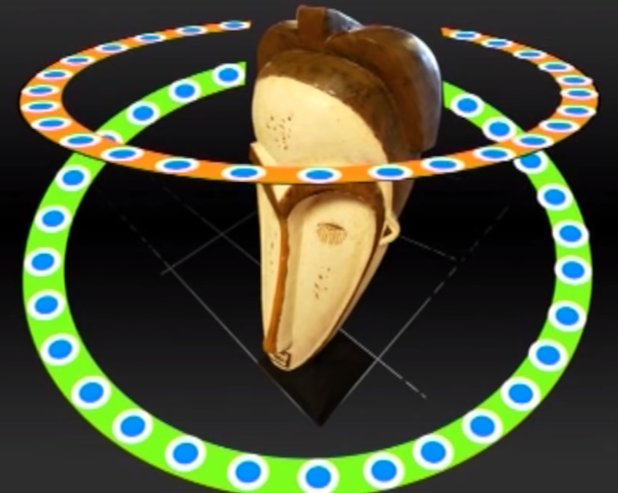
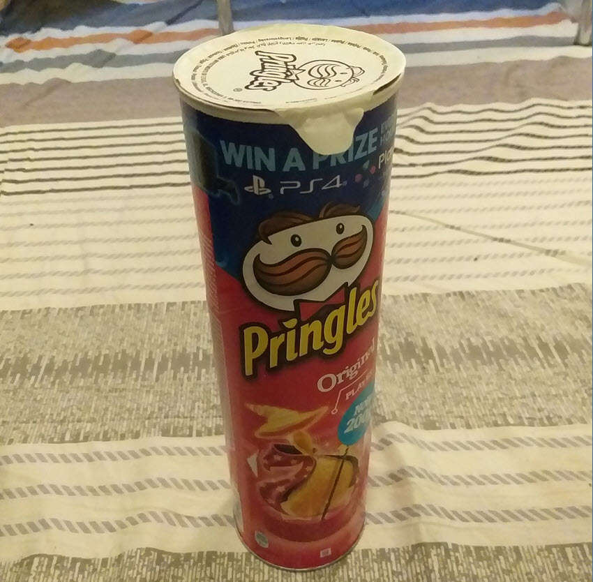
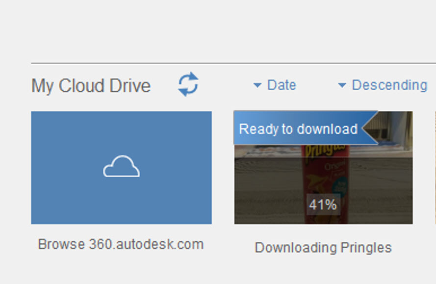
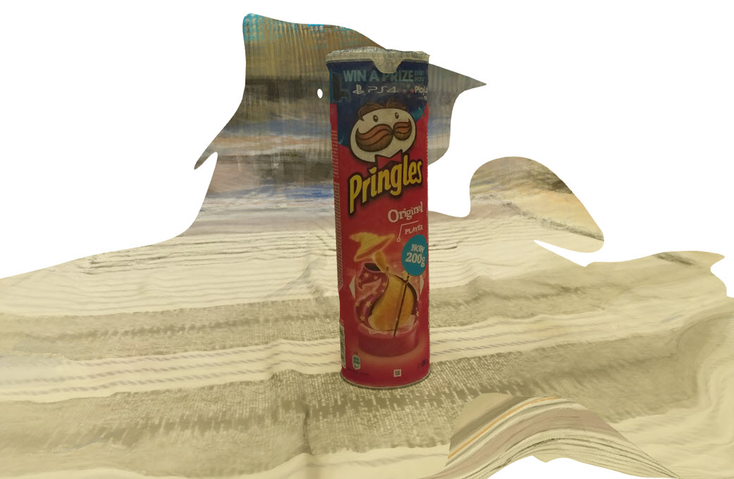
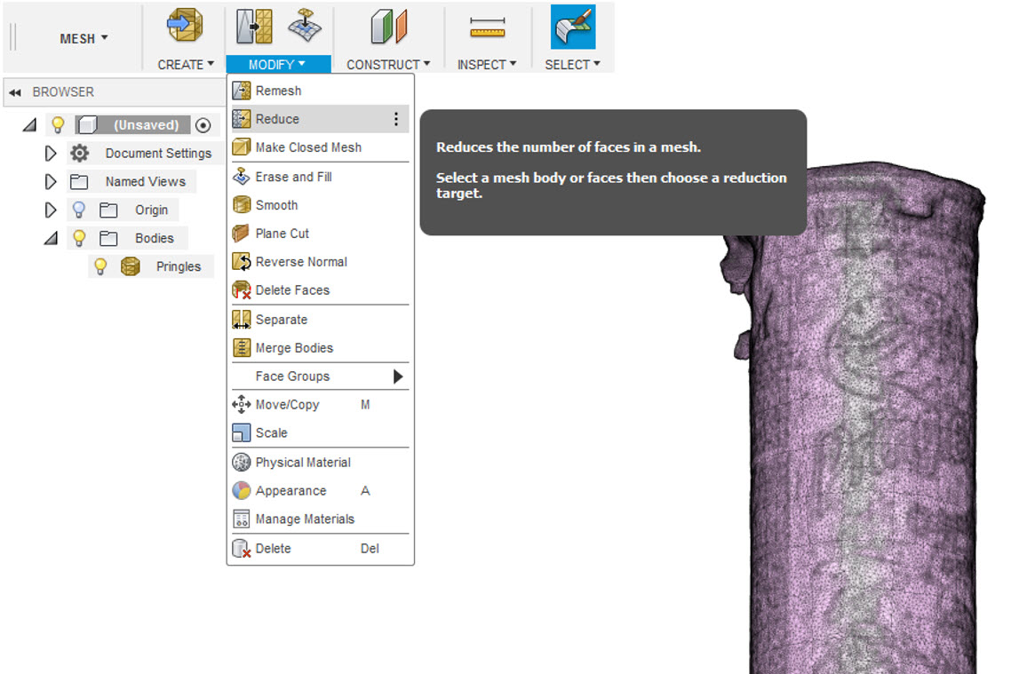
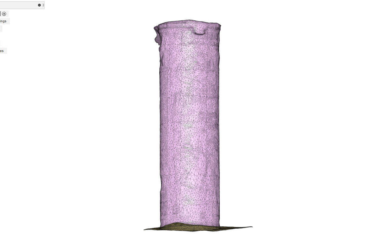
First, I selected a non-reflective object, the pringles box as shown in the picture then I took a series of pictures around it in the same way as I said earlier. After taking a series of pictures, I opened the Autodesk Reacap Photo and selected to create a 3D Model for an object and browse the folder containing the pictures. The minimum number of pictures we can give is 20 and the maximum is 100. I took 100 picures and uploaded them. After that, I created a 3D model of those pictures. The pictures are uploaded on the cloud drive for processing.
The processing takes 15mins to 1hour or more depending on the number of pictures taken, After processing, the file is ready to be downloaded. The downloaded file is in .rcm format which is then opened to view the 3D model created.
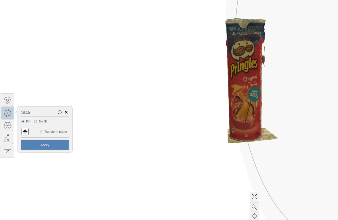
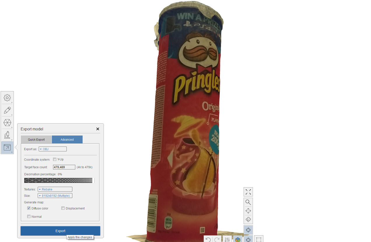
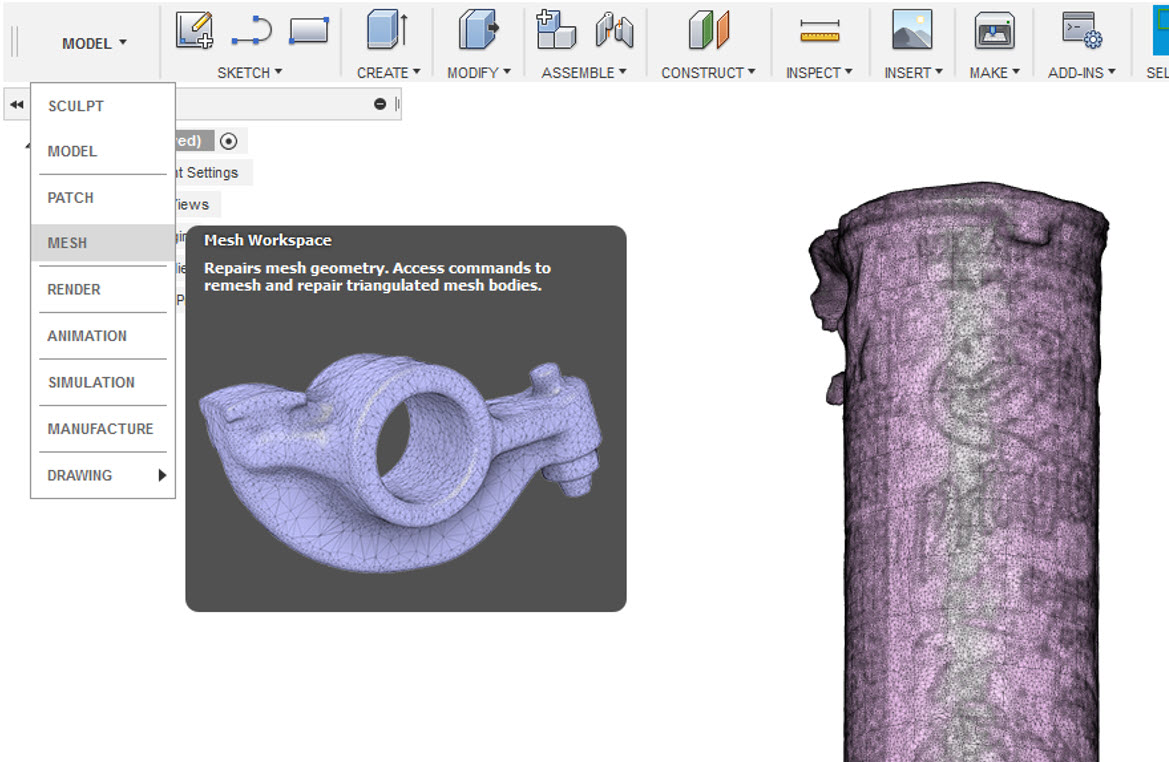
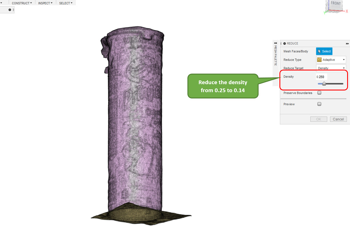
Next I used Edit-->Slice&Fill to crop the unnecessary stuff around the 3D object. After cropping, I exported the 3D model into .obj file inorder to open in Fusion 360. In Fusion 360, I selected the Mesh Window and changed the mesh settings i.e density from 0.25 to 0.14 to reduce the file size. Then, I exported the fle as .F3D file format as well as .STL file.
Reflection
This week was a very long week but in terms of learning, it helped me alot to know about different 3D printers, characterization and their limitations. The group work helped to find the best printer that guided me forward towards my Individual task which was additive in design (A Hinge Box). The designing of it took a lot of time with plenty of flaws that I had to correct it. In Scanning, I experienced failures in Sense 3D Scanner since after having a nice scan, I was not able to save the file. I move to Autodesk Recap Photo which is a powerful tool inorder to create 3D models and if the pictures are taken correctly, the 3D Model comes out to be really nice.
Resources Utilized
- I utilized these resources for this task:
- InsightTM
- slic3r software
- Sindoh 3DWOX software
- Autodesk Fusion 360
- Sense 3D Software
- Autodesk Recap Photo