Task 4
Computer controlled cutting
In this week, I was given a task to have a group assignment and an individual assignment. The group assignment was to Characterize your laser cutter, making test part(s) that vary cutting settings and dimensions whereas the Cut something on the acryliccutter design, lasercut, and document a parametric press-fit construction kit, accounting for the lasercutter kerf, which can be assembled in multiple ways.
Group Assignment
Characterization of the laser cutter
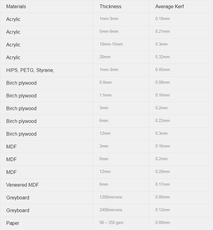
To start to characterize the Laser cutter, It was really important to understand the kerf. The term kerf is used to describe the thickness of the cut a laser makes in a piece of material as it cuts through it. We studied about what the kerf is and how it changes with different materials used for the laser cutting. This link http://www.supersoarlaser.com/kerf-first-thing-need-know/.
I found this website to be useful as well as it gave a description of the kerf and different materials which average kerf values that will eventually help us to verify the kerf values that we are measuring are correct or not.
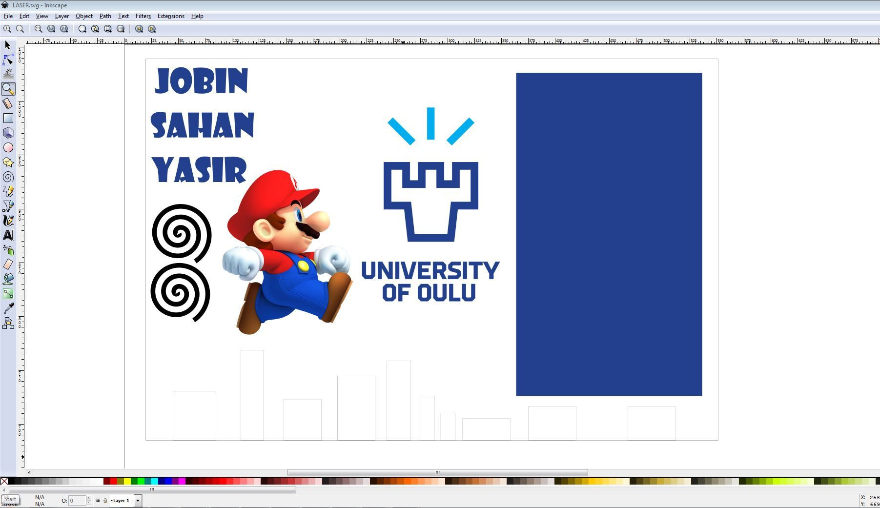
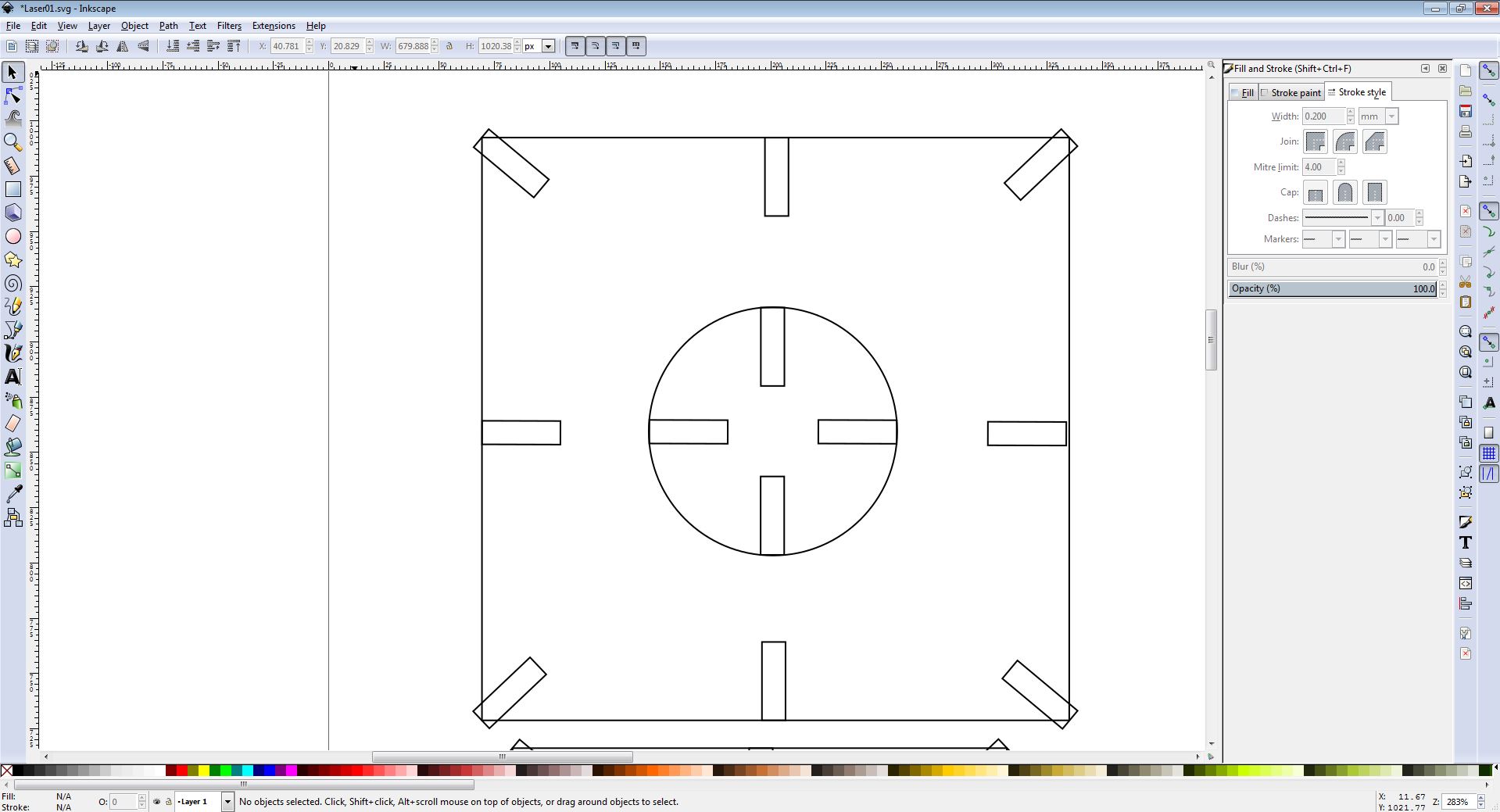
After understanding the concept of kerf, we started to work with out first laser cutting design. The design was performed on Inkscape. The first task was to measure the kerf of two different materials, we selected MDF Material 3 mm and the Acrylic sheet 3 mm.
Setting up the Machine
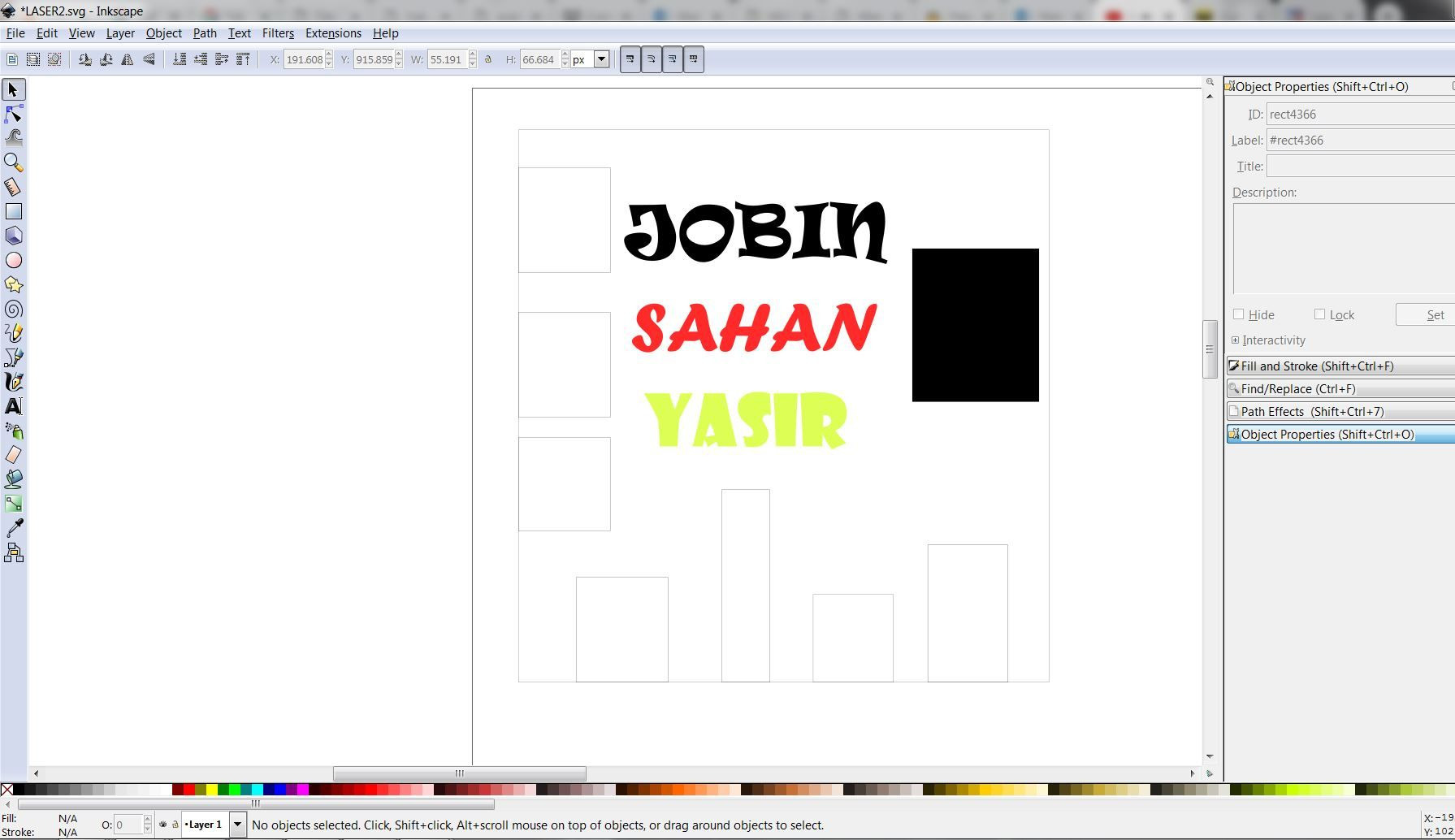
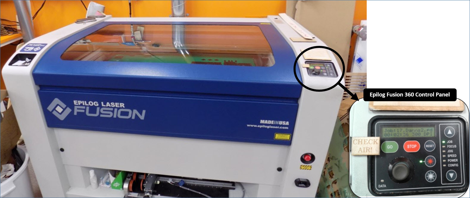
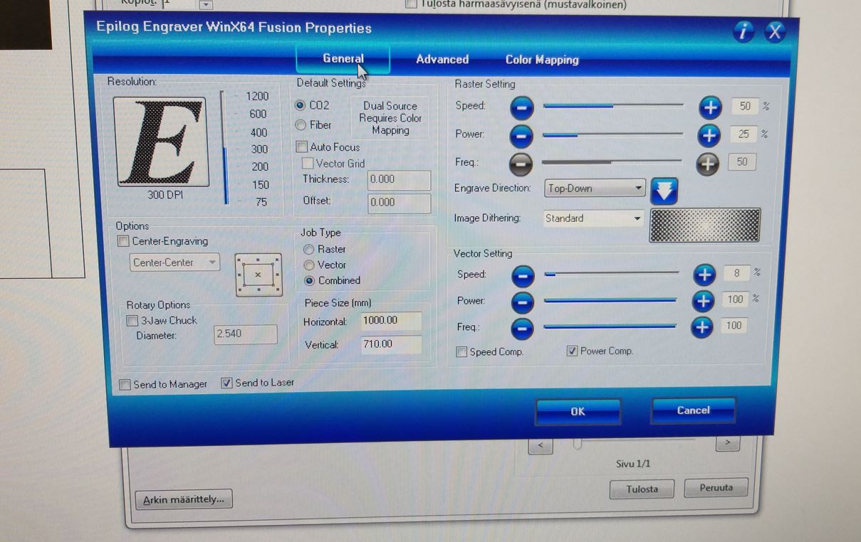
The machine used for the laser cutting and engraving is Epilog Laser Fusion 75 W. It has its own control panel as shown below:
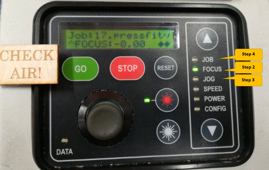
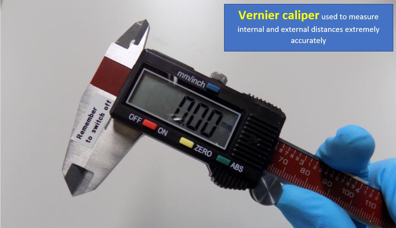
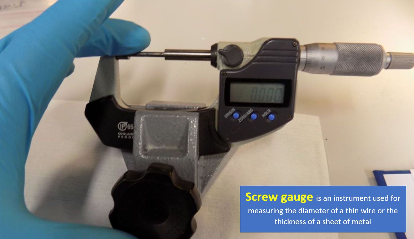
After doing the laser cutting of the two different materials, the next step was to do the measurements with the screw gauge to obtain the depth and using vernier calliper to obtain the required kerf. The kerf was obtained using this process using the below process.
Material Characterization with different settings and Tools utilized
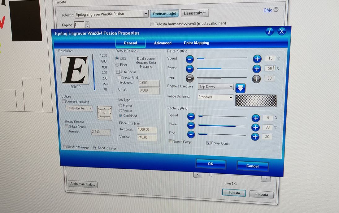
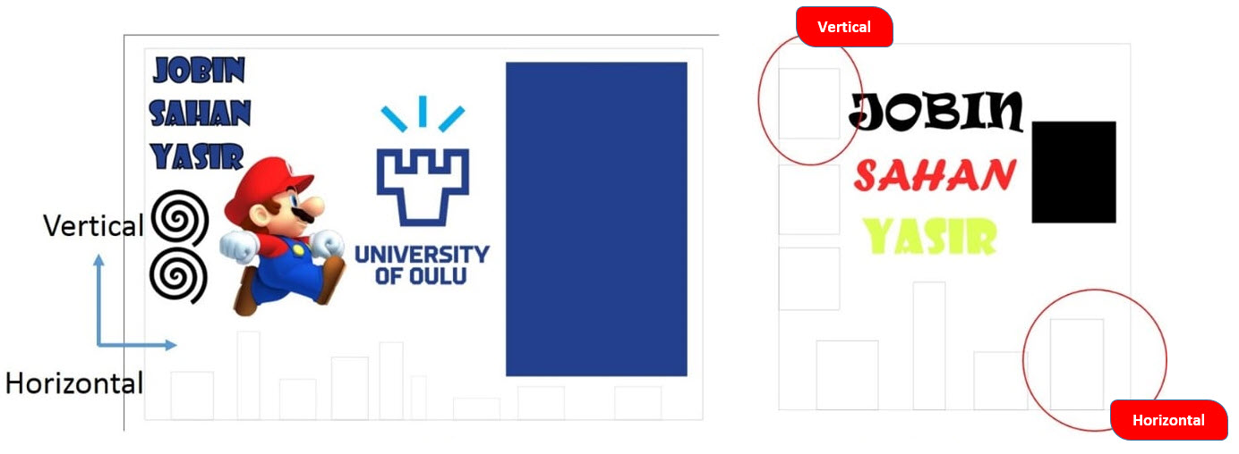
There are three options of Speed, Power and Frequency that can be adjusted for Raster and Vector. To measure the kerf, we decided to change these settings and observed the kerf with the change in these settings. The Design has horizontal and Vertical rectangles thereby the size of the rectangle was being compared after the cut.
Below tools were being utilized to calculate the kerf and the depth of the graving on acrylic and MDF material. Vernier Caliper was being utilized to calculate the kerf. Screw Gauge was being utilized to calculate the depth of the graving on material.
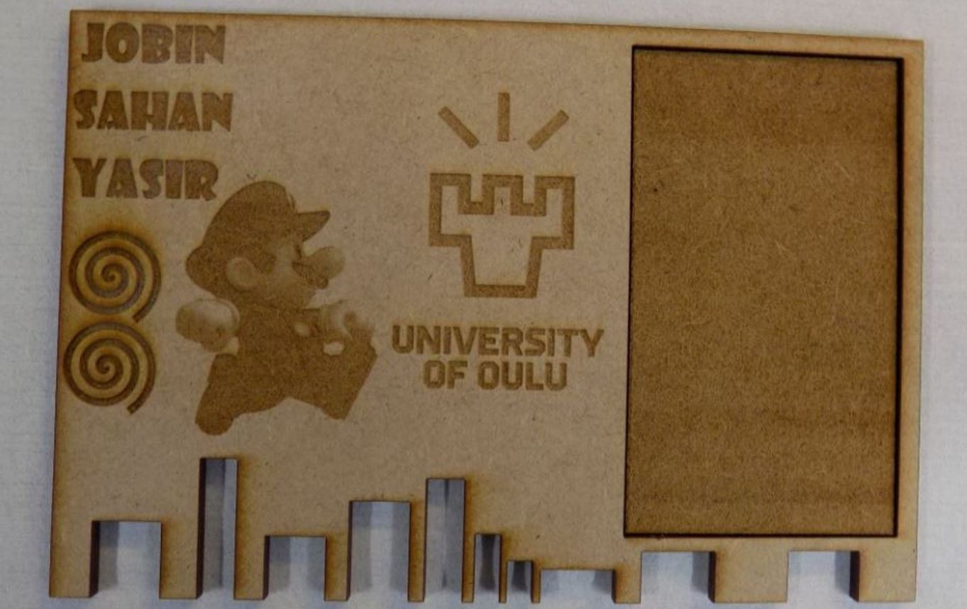
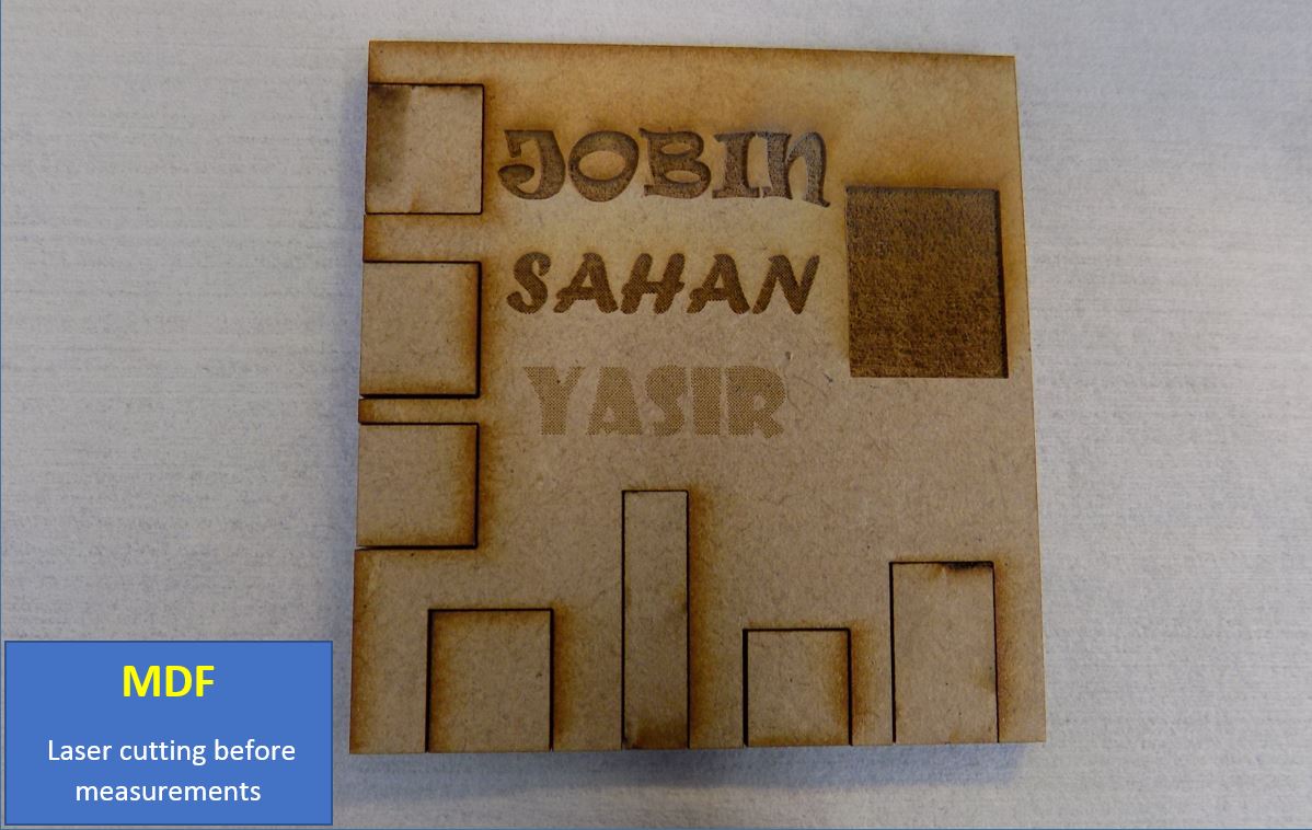
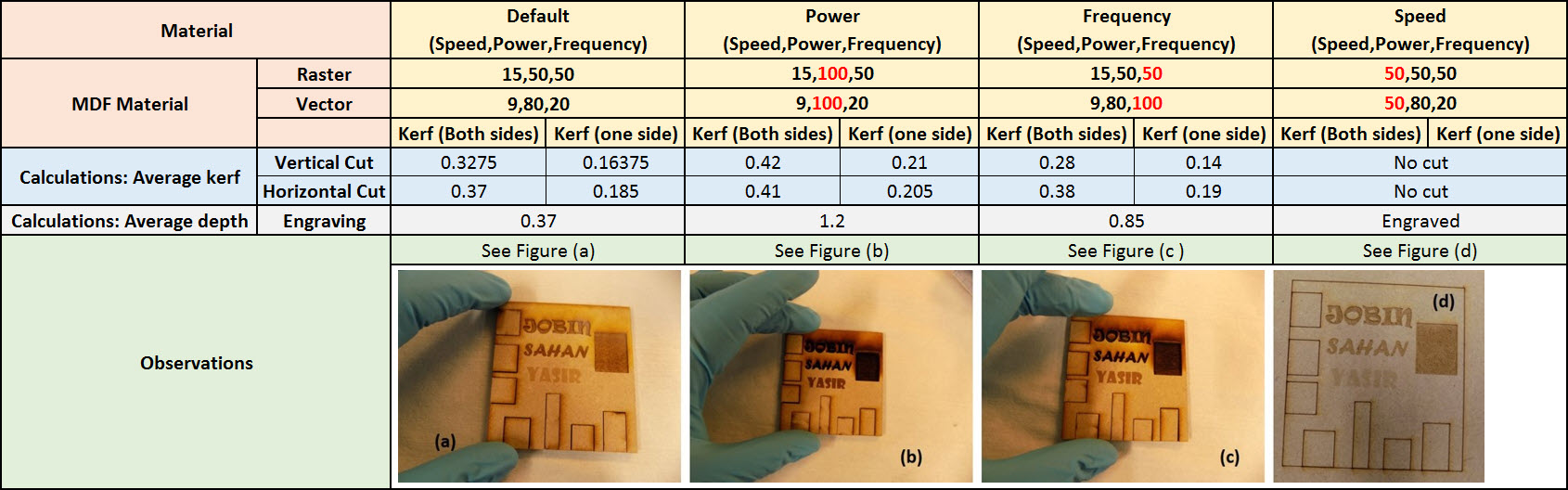
MDF Material Characterization with different settings
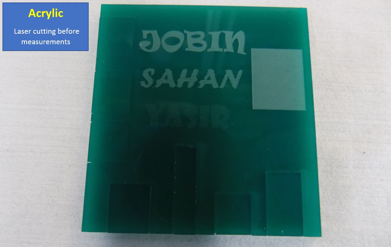
Acrylic Material Characterization with different settings
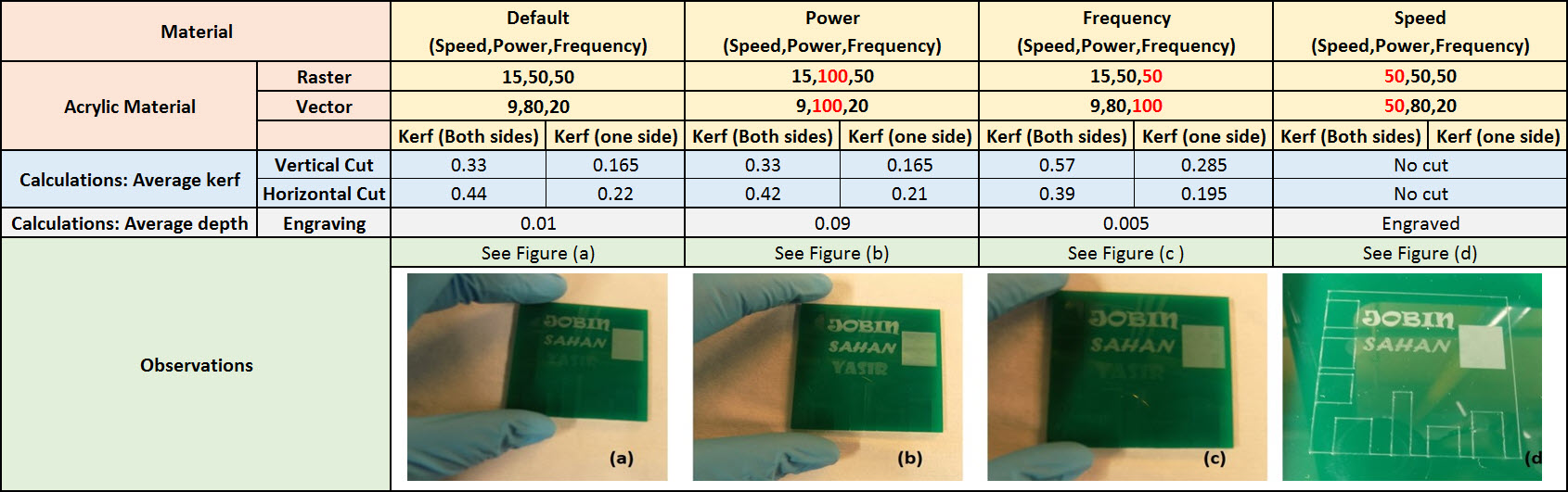
It can be seen from the figure that the change in laser parameters i.e. power, frequency and speed the engraving and the cut variations are being observed. It is recommended to use low power vector settings for a good cut. With the high power settings of raster the it was observed that image colour influences the engraving. With the increase in frequency settings for the raster and the vector, in the case of vector no cuts were being made. Line width was set to 0.02 mm for the design. The kerf value calculated based on the cut piece and cut area. Engraved depth measurement was done comparing the actual thickness before cutting and after engraved area. Materials properties are also factors which have a critical influence on laser characteristics.
Individual Assignment
Parametric press fit kit design
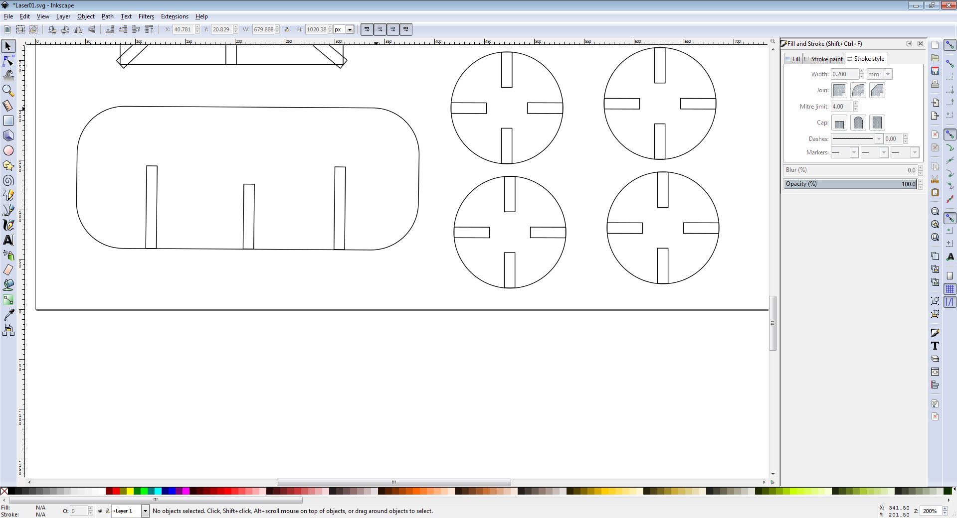
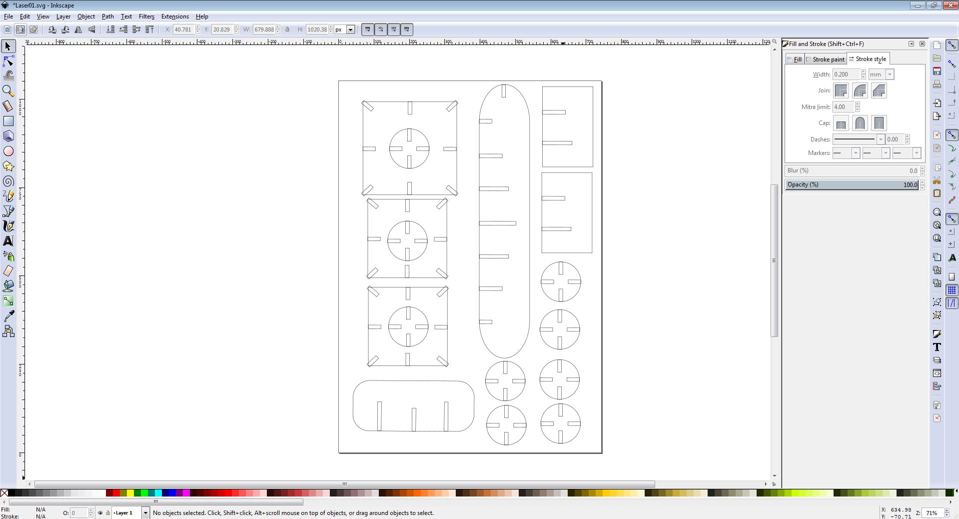
After drawing a clear sketch in Inkscape. I was inclined towards cardboard material to use for my press fit design construction due to its structural ease and better press fit. My Idea was to design a press fit structural using basic shapes like rectangle, circle and square.
- I followed below simple steps to create a sketch in Inkscape:
- Idea was to design a tower like structure
- Initially, I used the rectangle tool then I moved towards circle and square shapes.
- After drawing the basic shapes I used for the press fit design. I added the press fit slots.
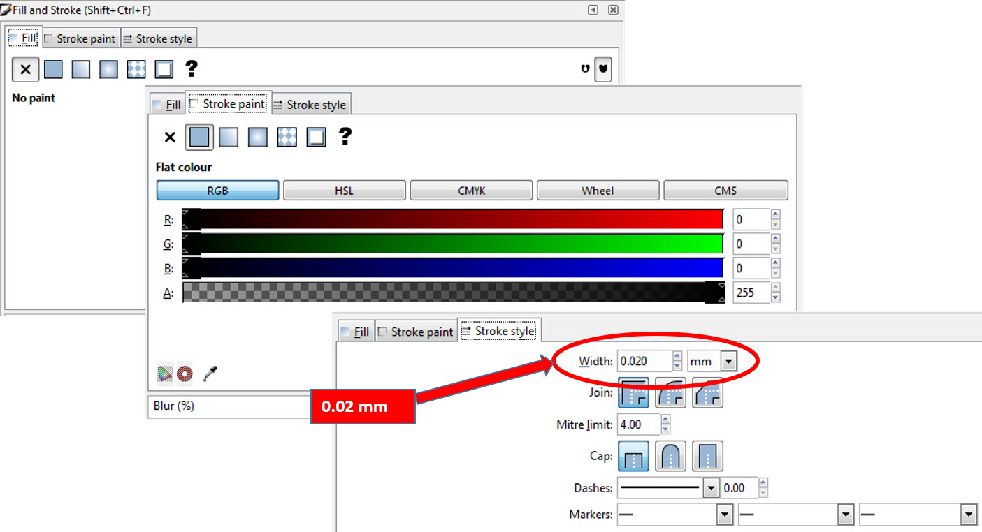
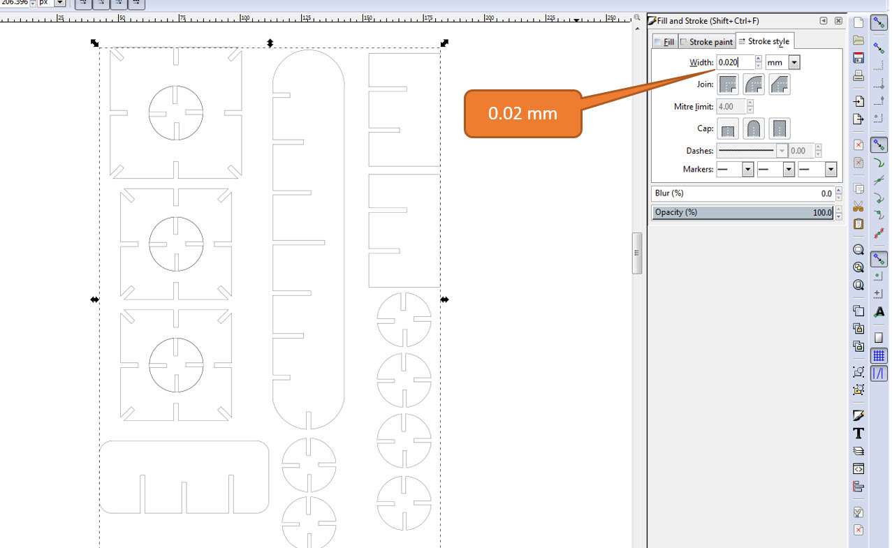
- After completing my design in the Inkscape. The design was all vector design. The stroke settings are very important, the width of the line should be 0.02 mm for laser cut, else no cutting will be performed.
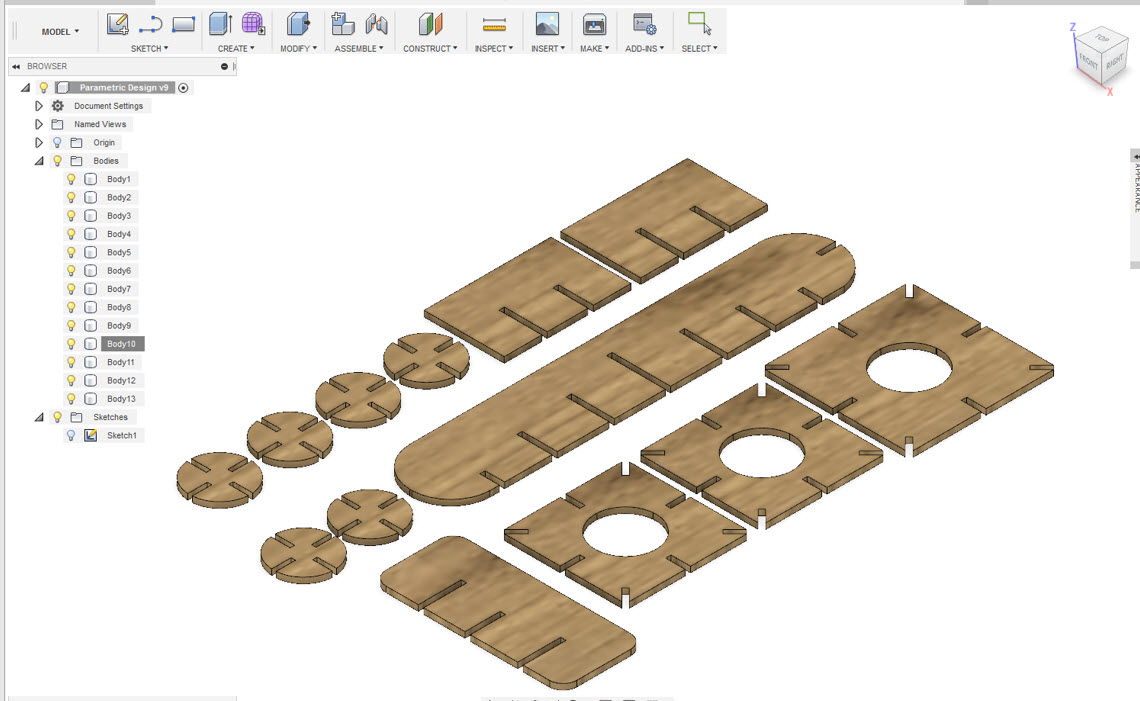
After drawing a clear sketch of my design in Inkscape. As suggested by our Instructor, the design shall be parameteric that means that we can increase or decrease the size of the design by changing parameters associated with it, instead remaking the whole design all over again. Thereby I utilized Autodesk Fusion 360 for this purpose, In Autodesk Fusion 360, I can make my design to be parameteric. I started my design by making the rectangle using the 2-point rectangle tool then I used the circle tool to make the circle as seen in the below figure. As every stage of the design, I assigned the necessary parameters.
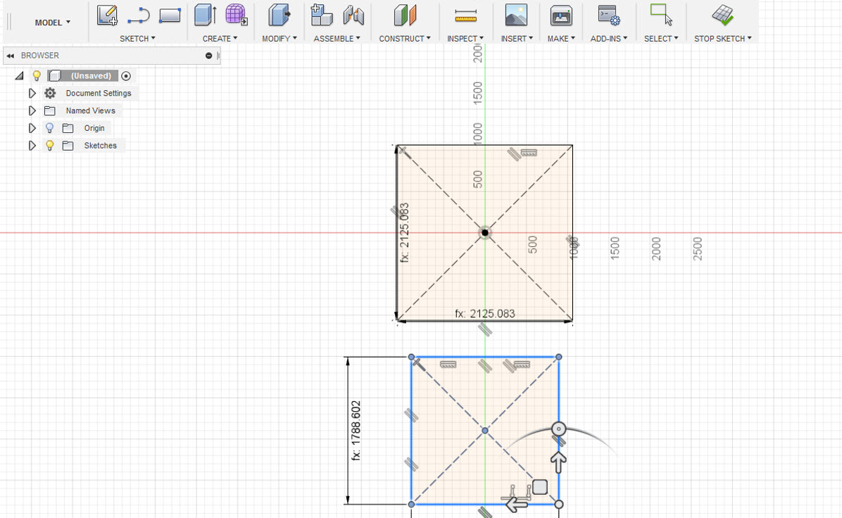
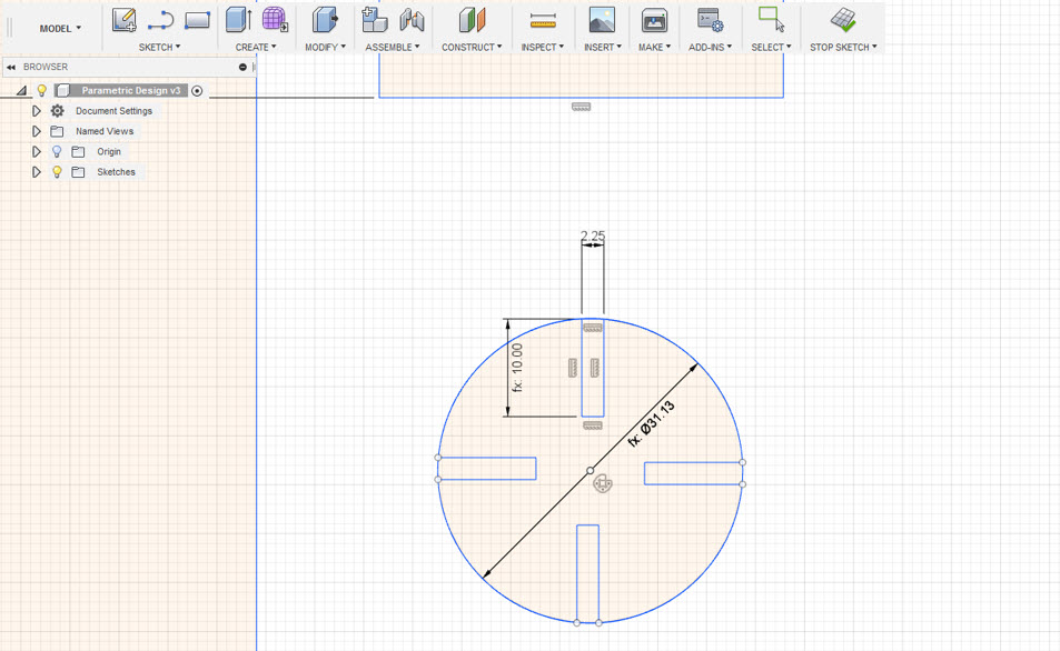
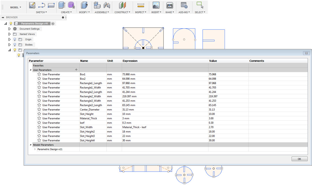
At every stage of my design, I assigned parameters which can be modified if I want to increase or decrease the size of my design. The main parameters are the kerf and the slot size which can be modified if I am willing to laser cut on a different material but I will use the cardboard material which has a thickness of 3mm.
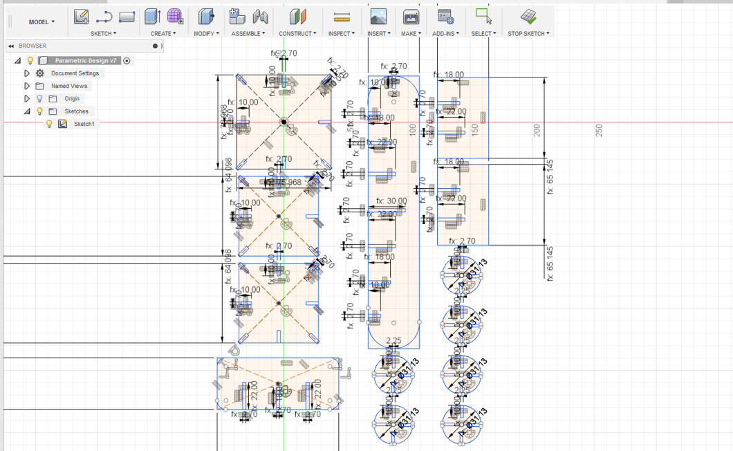
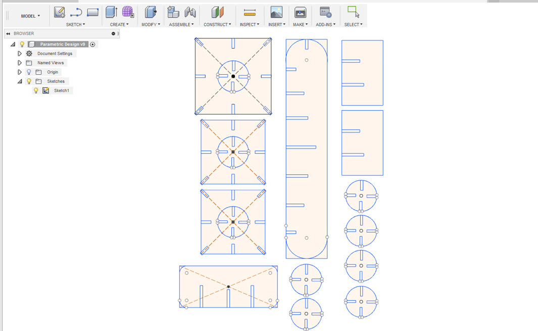
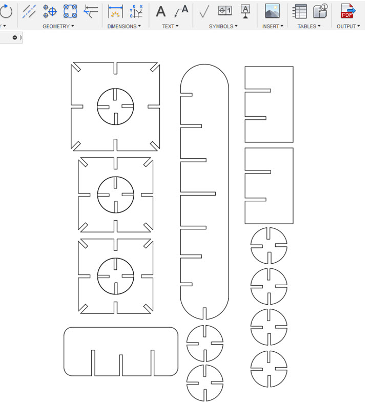
Below is the sketch representation of my design with the paramteric function dimensions being visible on the left side of the picture and a clean sketch on the right side. The design is completely paramteric and each dimension can be adjusted by changing the defined parameter value.
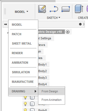
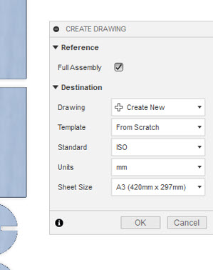
After designing the sketch, I extruded the design to my material thickness i.e. 3mm, then I change the appearence. The next step was to export it into pdf for this purpose we have to extract the drawing from the design. Goto Model-->Drawing-->From Design then a dialog box will appear displaying the information of units, sheet size and template settings. Press OK.
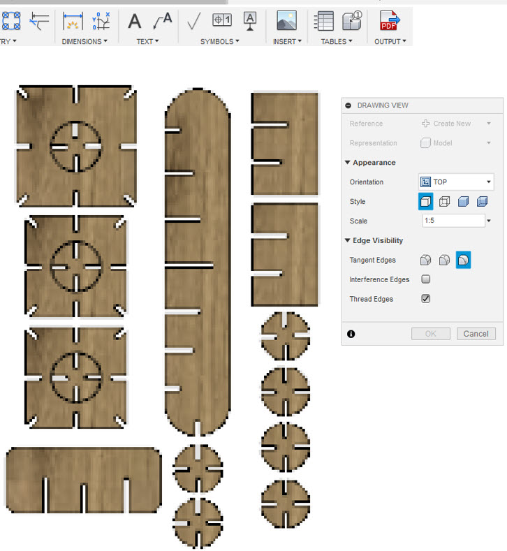
After this a new drawing window will open. From the drawing view I selected the layer where I drew the sketch i.e Top Layer. Then I pressed Ok and I got an drawing of the design as seen below in the picture on the right.
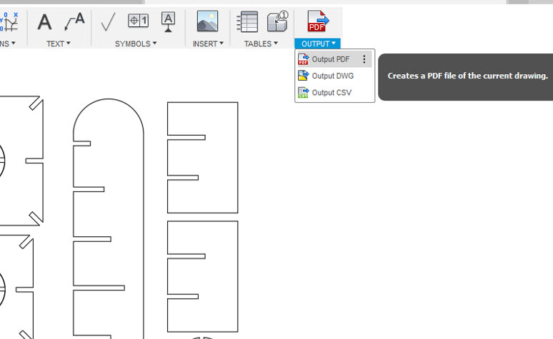
The next step was to export the drawing in PDF format, for this Goto-->Output-->Output PDF then I opened the PDF in Inkscape and selected the stroke width to 0.02mm for the cutting and then export the design again in PDF
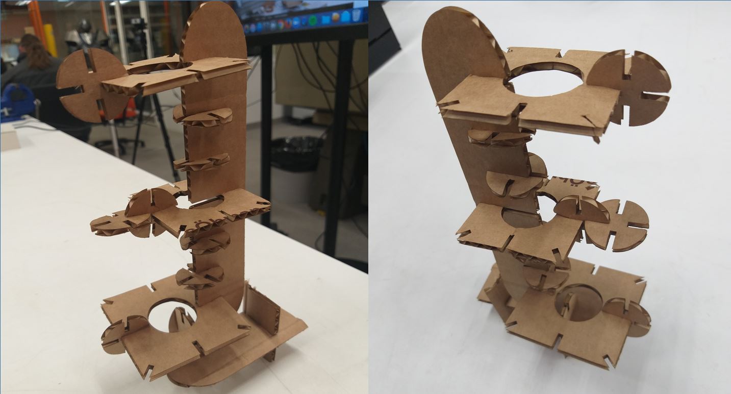
After this, I laser cutted the design and assembled it as seen in the pictures below. The Tower structure laser cutted and assembled and it easily fits into one another. I didn't had to modify the design, the slot width and height were perfectly fit into one another.

Vinyl Cutting
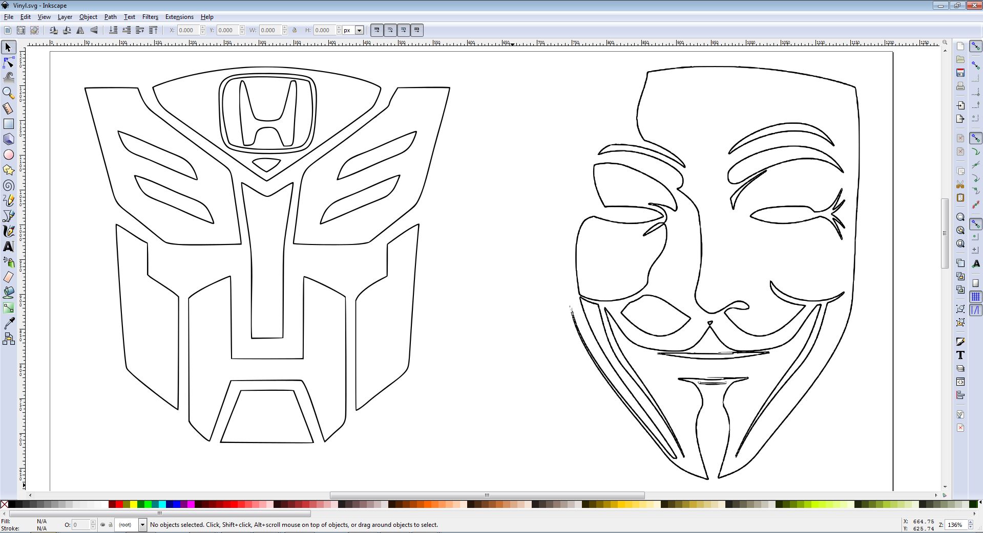
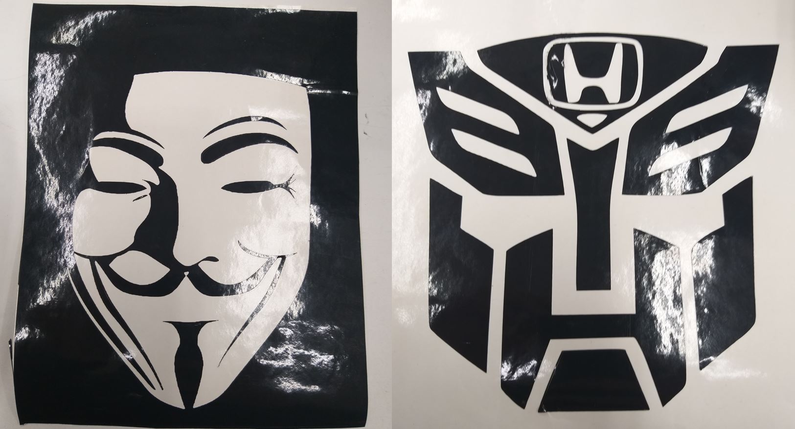
For the Vinyl cutting, I used Black and white images from Google Images Vendetta Mask and Transformer Mask.
- I followed below steps to create the Vinly cutting setting from Inkscape:
- Open the required black and white image.
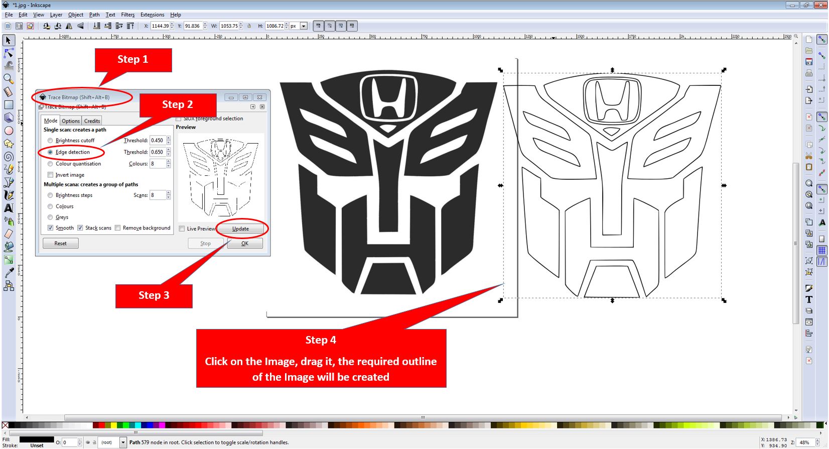
- Vinyl cutters are similiar to a desktop printer. Like a printer controls a nozzle, the vinyl cutter controls the movement of a sharp blade over the surface of the material. This blade is used to cut out shapes and letters from sheets of thin self-adhesive plastic (vinyl). Since each drawing requires a clear outline of the drawing to cut on vinyl, as my picture was Black and white with black colour filled inside shapes thereby inorder to create and outline, I used a built-in utility in Inkscape known as Trace bitmap. The Trace Bit Map can be opened with a shortcut (Shift+Ctrl+B). Then I selected Edge Detection since I am willing to detect the edges in my picture that will eventually create the shapes. After doing that, I selected Update and the outline is now created. I clicked on the image, dragged it, and an outline can be seen now. The Line width of the Outline was 0.4mm.

- After acheiving the required steps, the next step is to setup the machine. The Machine that we are using for the vinyl cutting is Roland GS-24 and below things are important to consider before we start working on the vinyl cutter:
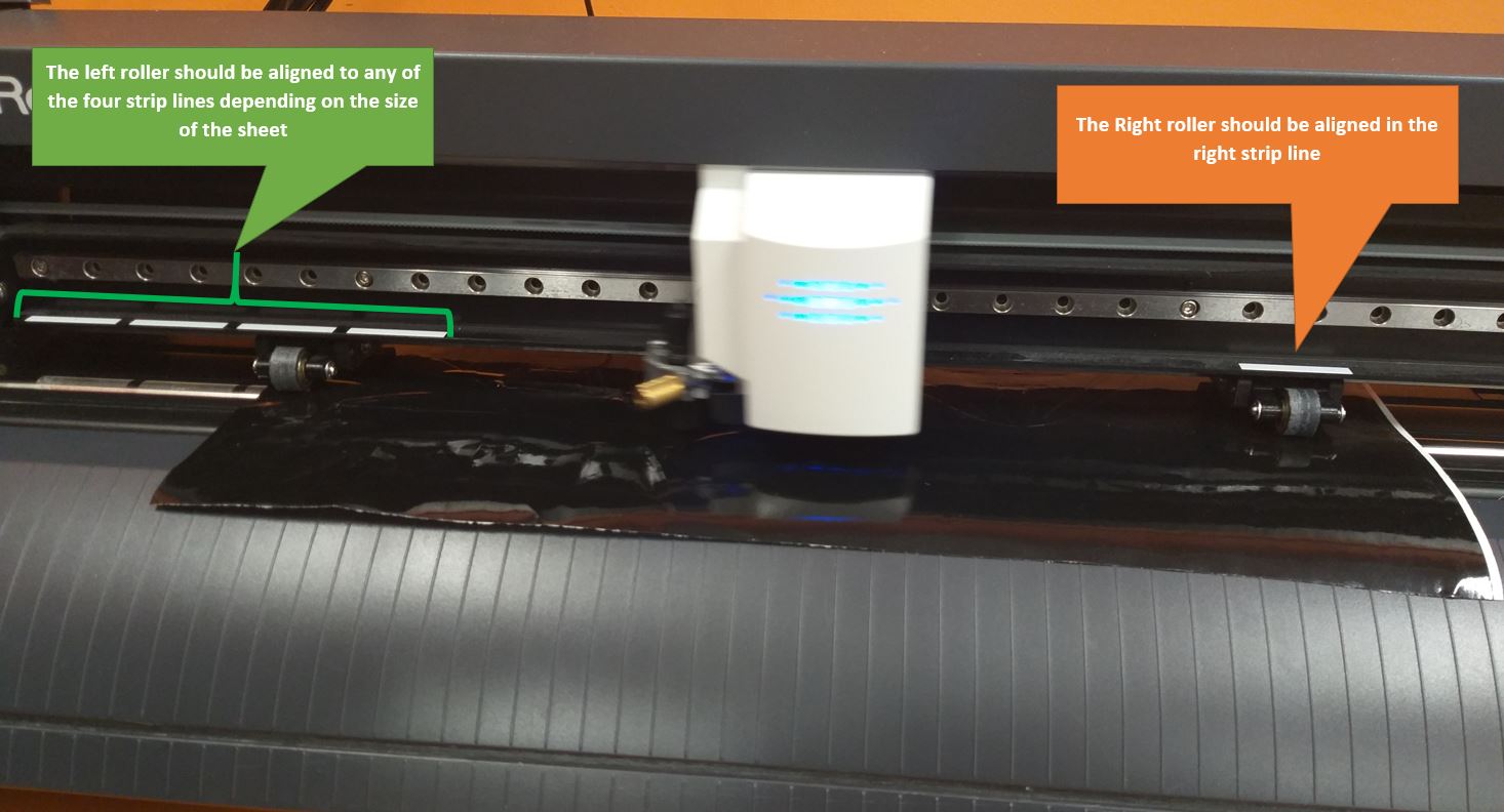
- As shown in the picture below, the rollers should be placed correctly. The Idea is there are four white markings on the left and there is one marking on the right. The roller should be placed on these markings, one roller on any of the four markings left and the other roller on the right roller on the right marking. The sheet size should fit between the left and the right markings.
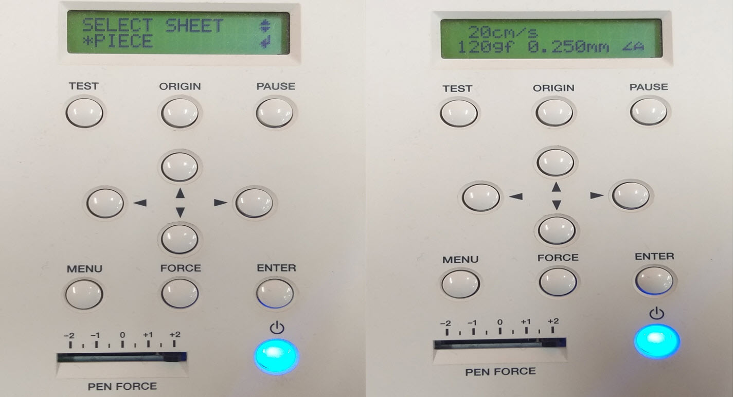
- I placed the coloured sheet on the machine, pulled the lever to hold the sheet in place and positioned the rollers which should be aligned on the grit marks to set the cutting area as seen in the picture below. The Pen force was +2. From the Vinyl Control Panel, I selected the option Piece with the arrows and set the origin and pressed Enter. The size the of the piece (the design to be cut) is measured and displayed on the screen. The Piece Measures the length and width of your material via all three sensors. This is especially helpful if you are working with a scrap piece of material. The other options are Roll (setting up the starting point manually) and Edge (Letting the machine only find only 1 side of your loaded material. when you just want to find the starting point at the edge of your material). From the computer, open the design (Print-->Printing Preferences). In the cutting area, select Get from Machine to get the right dimensions that were set from the machine’s control panel. Then press the Print Command.
Reflection
The Weekly Task was lengthy and time consuming. At first, I studied the kerf and the general recommended values of kerf for different materials. In the group, we learned how to find the kerf that really helped me to find the kerf for my individual assignment. I started with the press fit construction on Inkscape then I moved to Fusion 360 to make the design parametric. Working with fusion 360 helped me to learn with advance controls and shortcuts. The Vinyl cutting is important, as the sheet may sometimes not cut correctly, as I have seen with my class fellows. I was lucky enough to get it cut on one attempt. It was really a good experience playing with the vinyl cutter.
Resources Utilized
- I utilized these resources for this task:
- Inkspace, for 2D Modelling
- Fusion 360, for 3D Modelling
Files
- Group Task : SVG 1 file
- Group Task : SVG 2 file
- Individual Task : Sketch: Inkspace File
- Individual Task : Press Fit Construction Set (Inkspace File)
- Individual Task : Press Fit Construction Set (STL File)
- Individual Task : Press Fit Construction Set (F3D File)
- Individual Task : Press Fit Construction Set (PDF File)
- Individual Task : Vinyl Cutting