Final Project
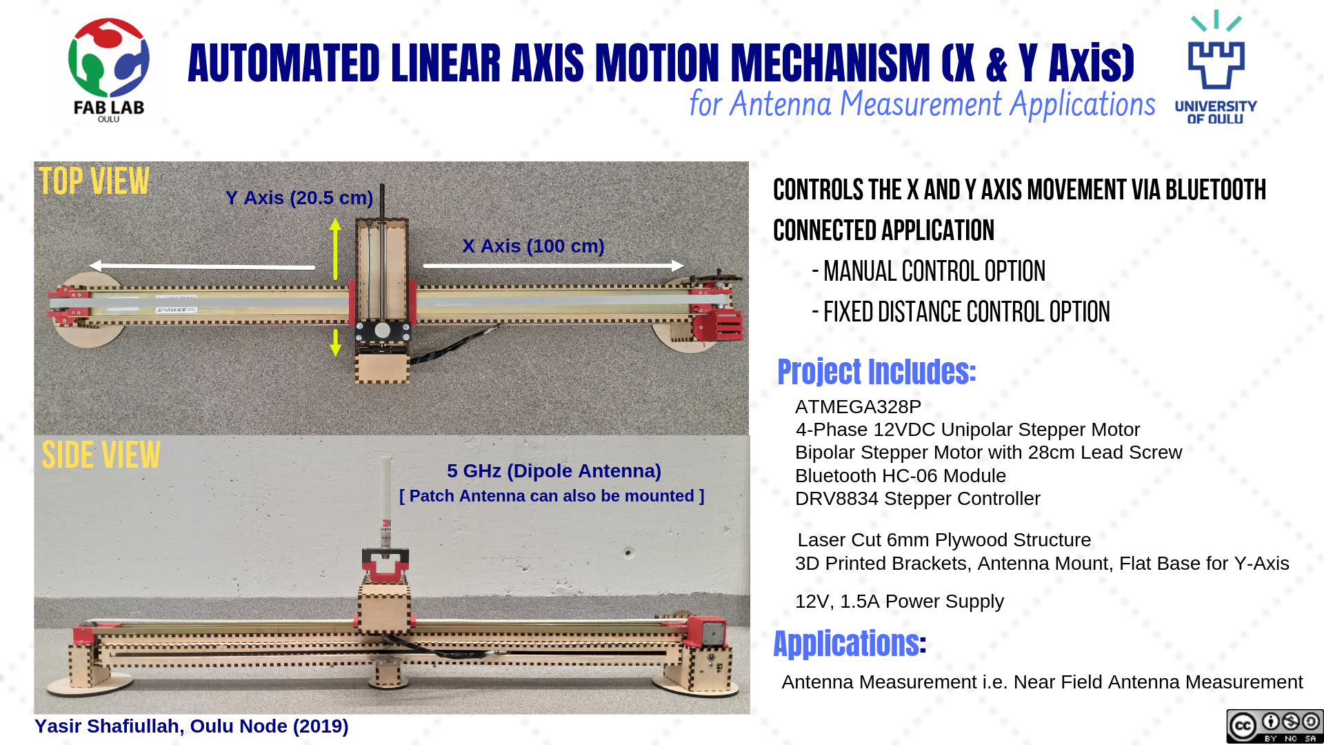
Automated Linear Axis Motion Mechanism for Antenna Measurement Application
Project Sketch
I came up with the sketch of an idea which I would like to implement using this Fab Lab Course
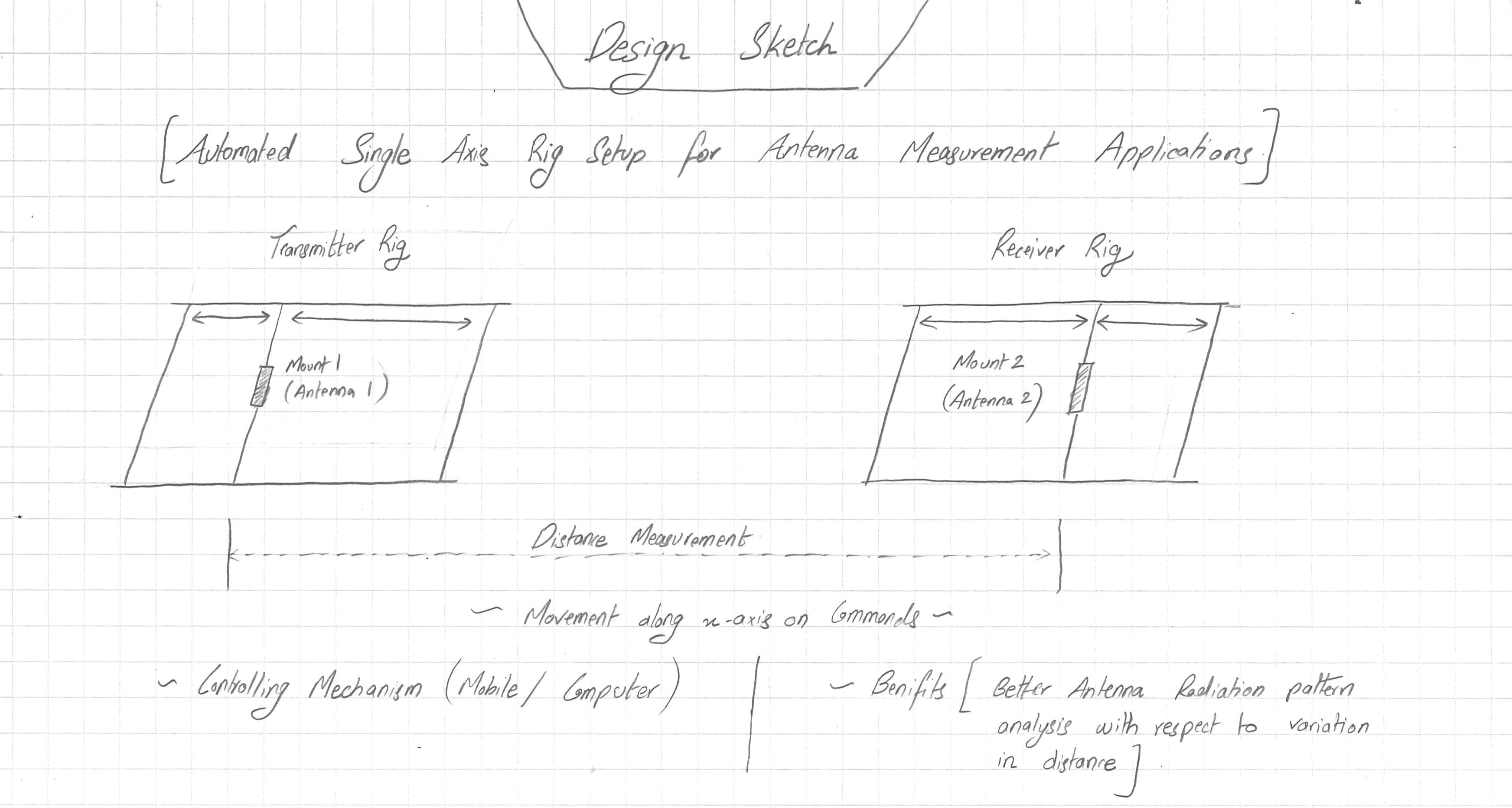
As seen in the sketch, the Idea is to create a Linear Moving axis Rig on which the Antenna or Radiating device can be placed. The Linear Motion will be Automated using a Microcontroller . The Interface can be a Mobile app or computer controling the motion along the Linear Axis. After the success of 1 Rig, I am planning to replicate the same Rig. Therefore, One Rig will be for the Transmitter and the other Rig will be for the Receiver. When 2 Rigs will be implemented the respective Automated Controls will also be implemented. Moving on, I would like to add some sensors like Ultrasonic sensor to measure relative distance between the Antennas. The Rig setup will alow me to place Transmitter and Receiver on both Rigs and correspondingly move them using Automation and check how the reciever behaves when the distance is being varied.
What will it do?
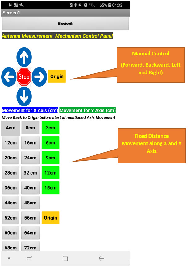
The Project will be an Automated Linear Axis Motion Mechanism that has the capablity to move in the X and Y axis as per command. The Number of turns of the motor will be utilized to measure the distance being travelled by the Linear Motion in either axis and the bluetooth will be utilized as an interface to control these motions. The Project will be useful in the Antenna Measurements Laboratory where the Antenna can be mounted on top and moved Linearly in X an Y direction and to analyze Radiation Patterns variations with respect to distance.
Who's done what beforehand?
- I have seen previous year FAB Academy students who utilized the linear motion rail, but the purpose of that was completely different.
- I was inspired by plenty of Antenna Measurement Systems on Youtube
What will you design?
- I will design the following:
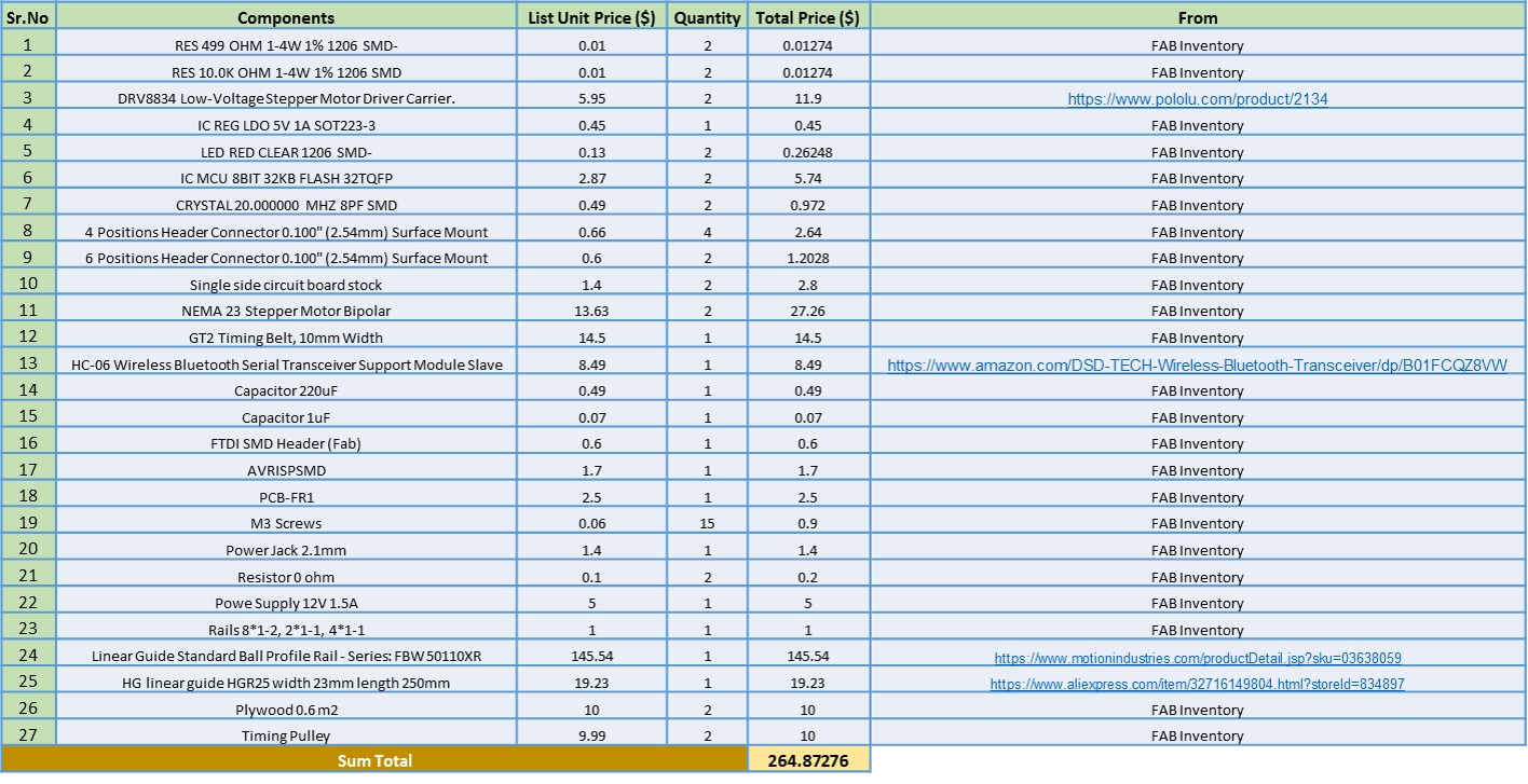
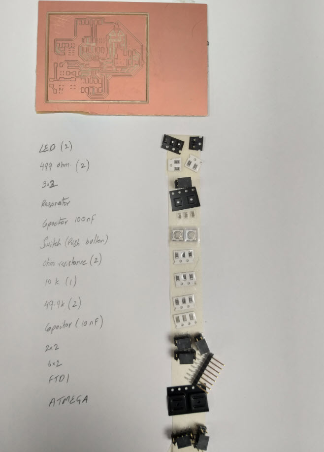
What materials and components will be used?
Where will it come from?
How much will they cost?
I will get the required components and materials from Fab Inventory, Although there are some Matrials and components which are needed to be purchased from other shops.
- I will design the following:
What questions need to be answered?
The linear mechanism with the timing belt shall provide enough torque so that the Antenna Mounted on top of it can be moved easily. The second important is the control of Axis, I am planning to use the Bluetooth module HC:06 and I have to design a custom application for that.
How will it be evaluated?
The Movement along the X and Y Axis shall be controlled by the Application on mobile/PC. When provided a certain distance to move the Antenna mounted on top shall move in a particular direction for the defined distance. Also if a manual control of movement is done with arrow keys to move forward, backward, left or right. The Project shall be able to do that. Apart from movement, the motion shall be smooth without any woobling, it shall be stable. The Motor shall provide enough torque and the complete structure on the floor shall be stable.
Planning
I planned the schedule to perform each task in my design
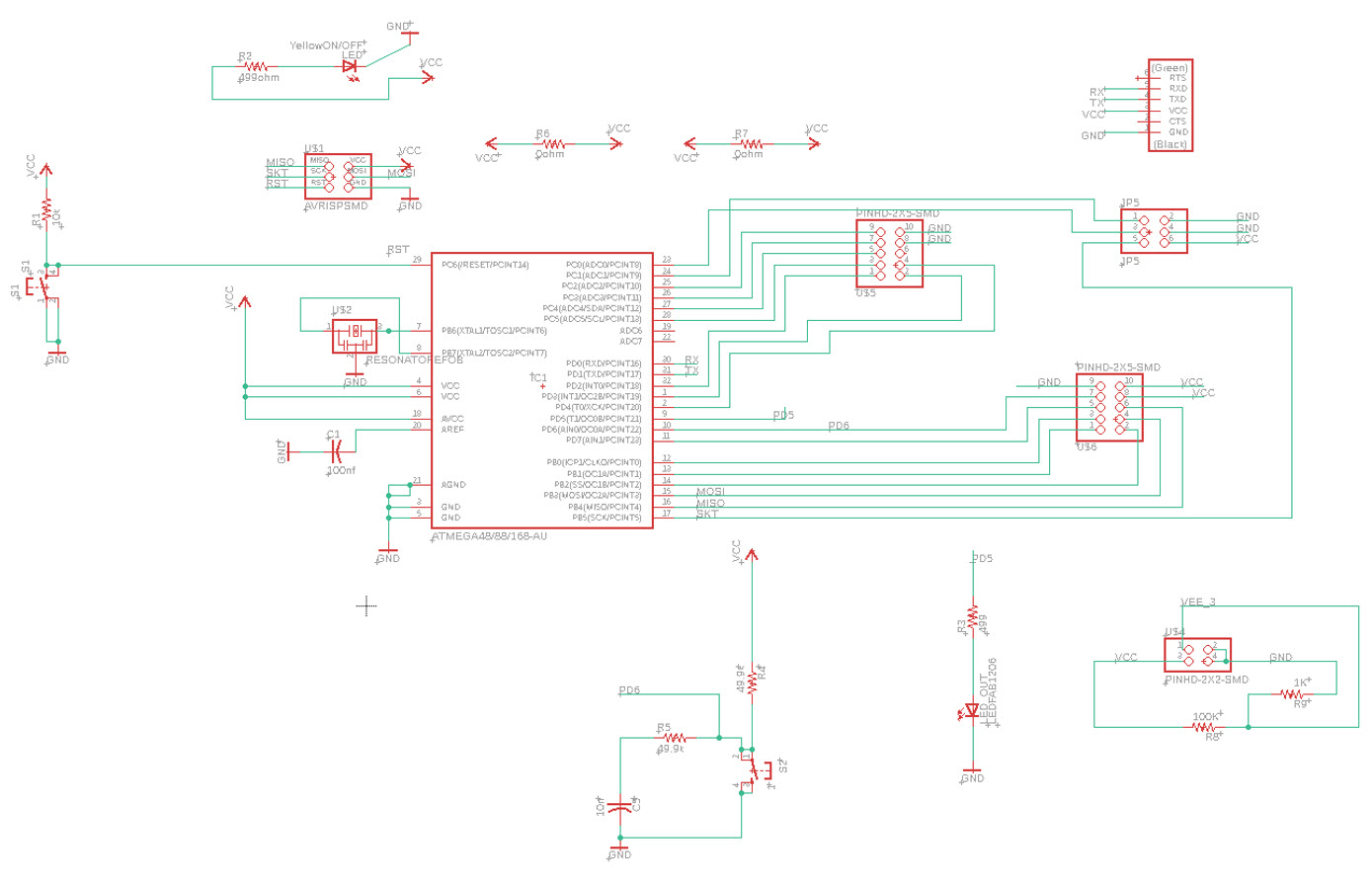
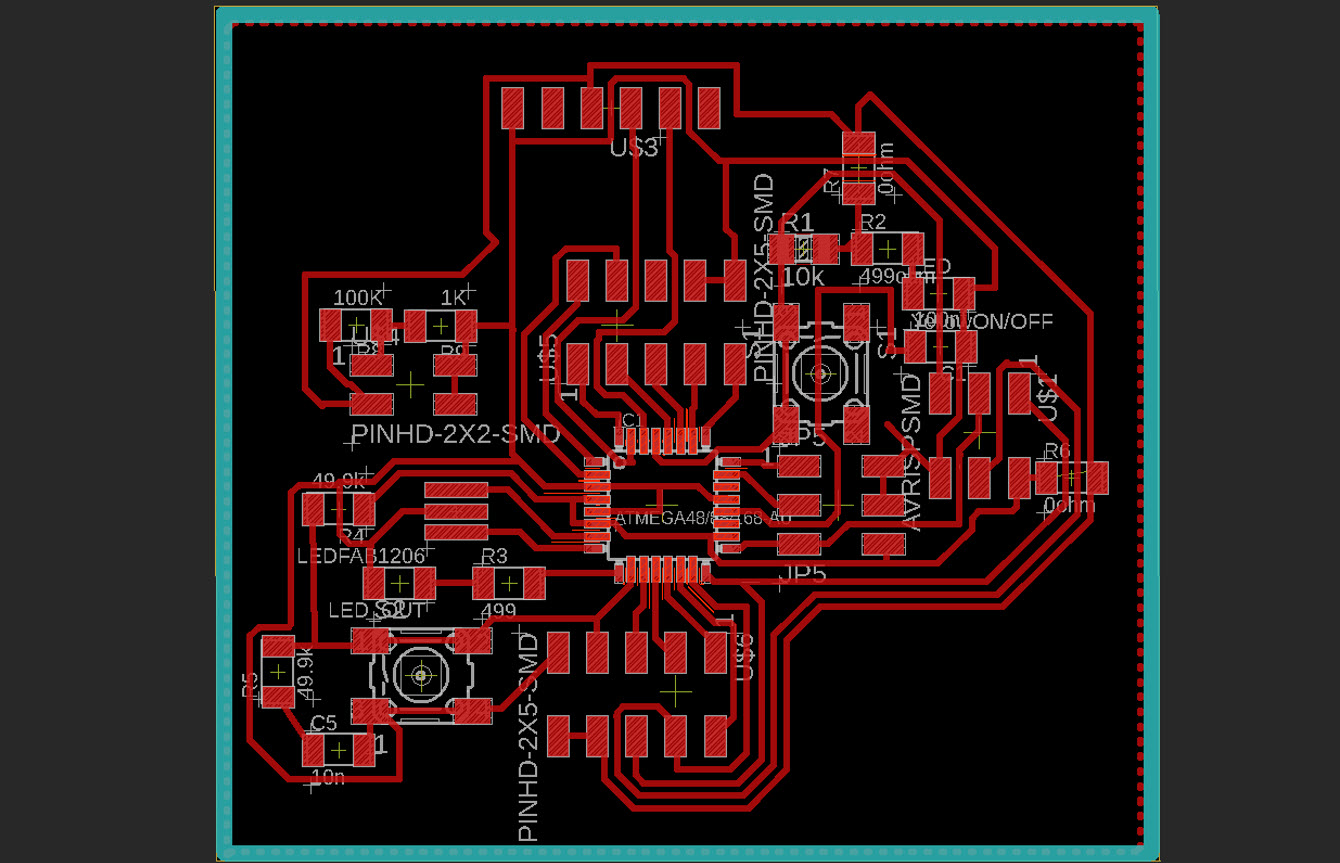
Electronics Design and Production:
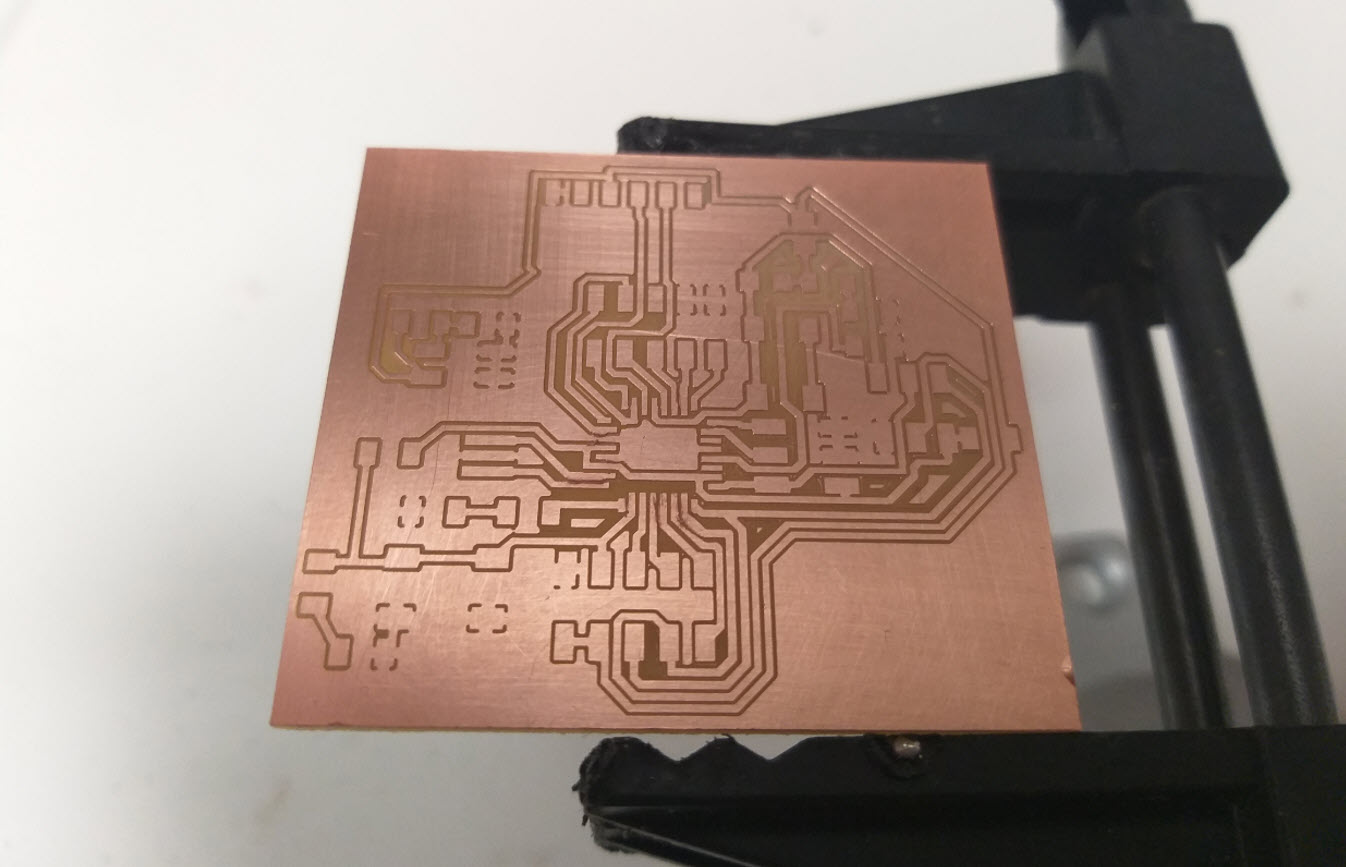
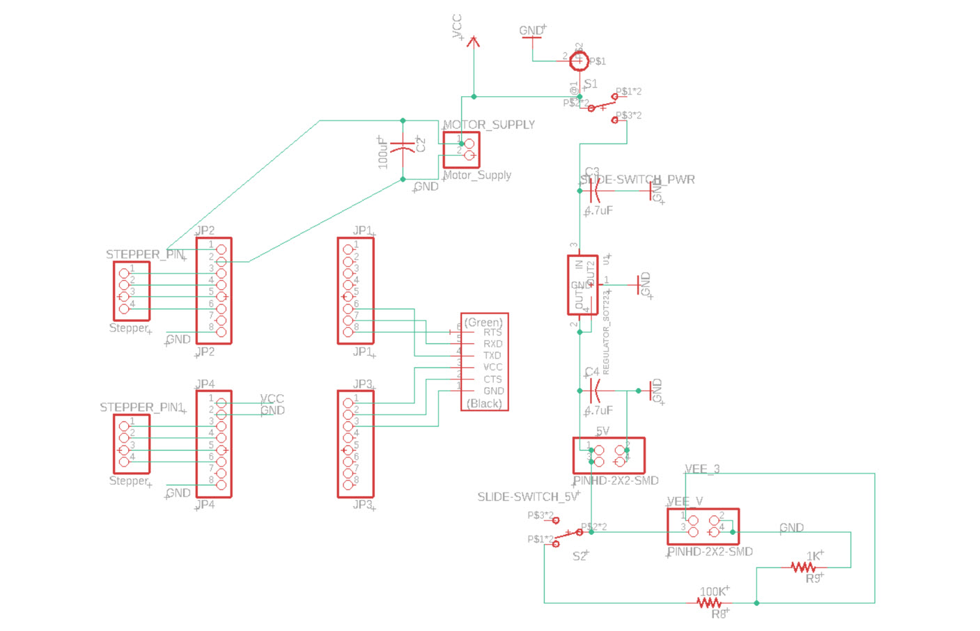
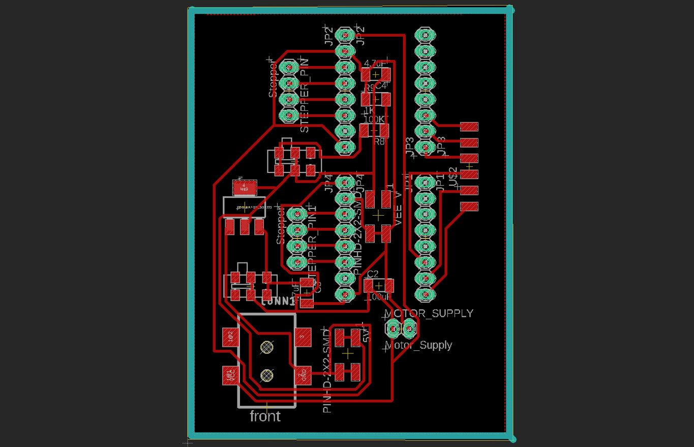
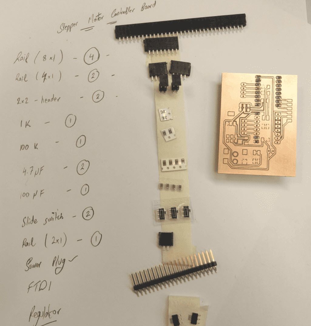
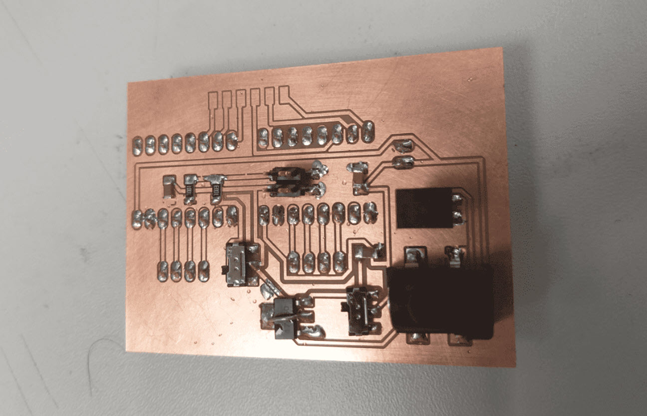
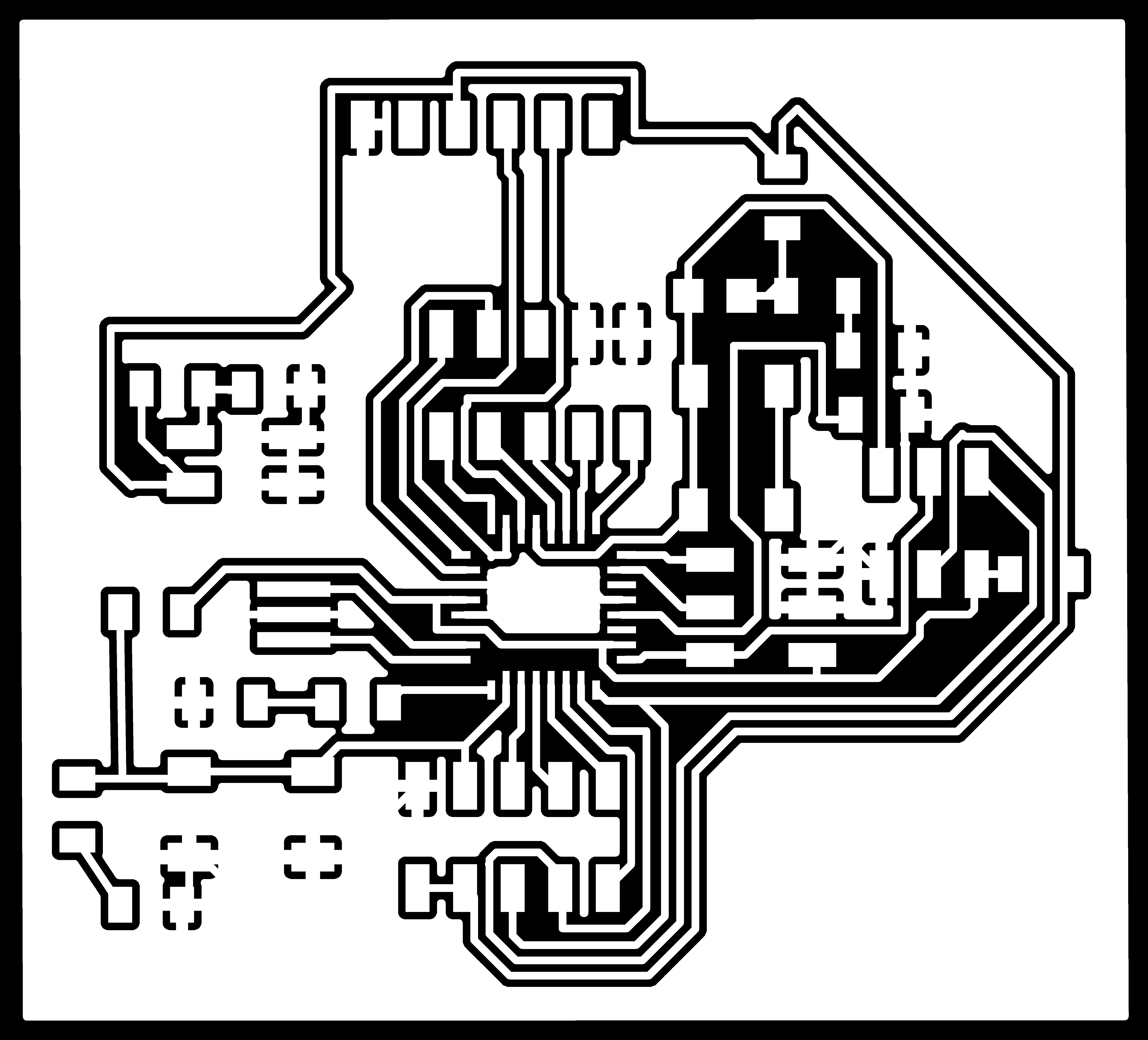
Since, I was planning to use more number of I/O pins for my final board which included the 2 stepper motors and the bluetooth module some switches and LED as well thereby I decided to use ATMEGA 328P. I utilized the knowledge, I gained from the Weed 5 and Week 7 to design the board on Eagle with the required number of compoents that I need. I decided to split the board into Two Parts:
Main Board
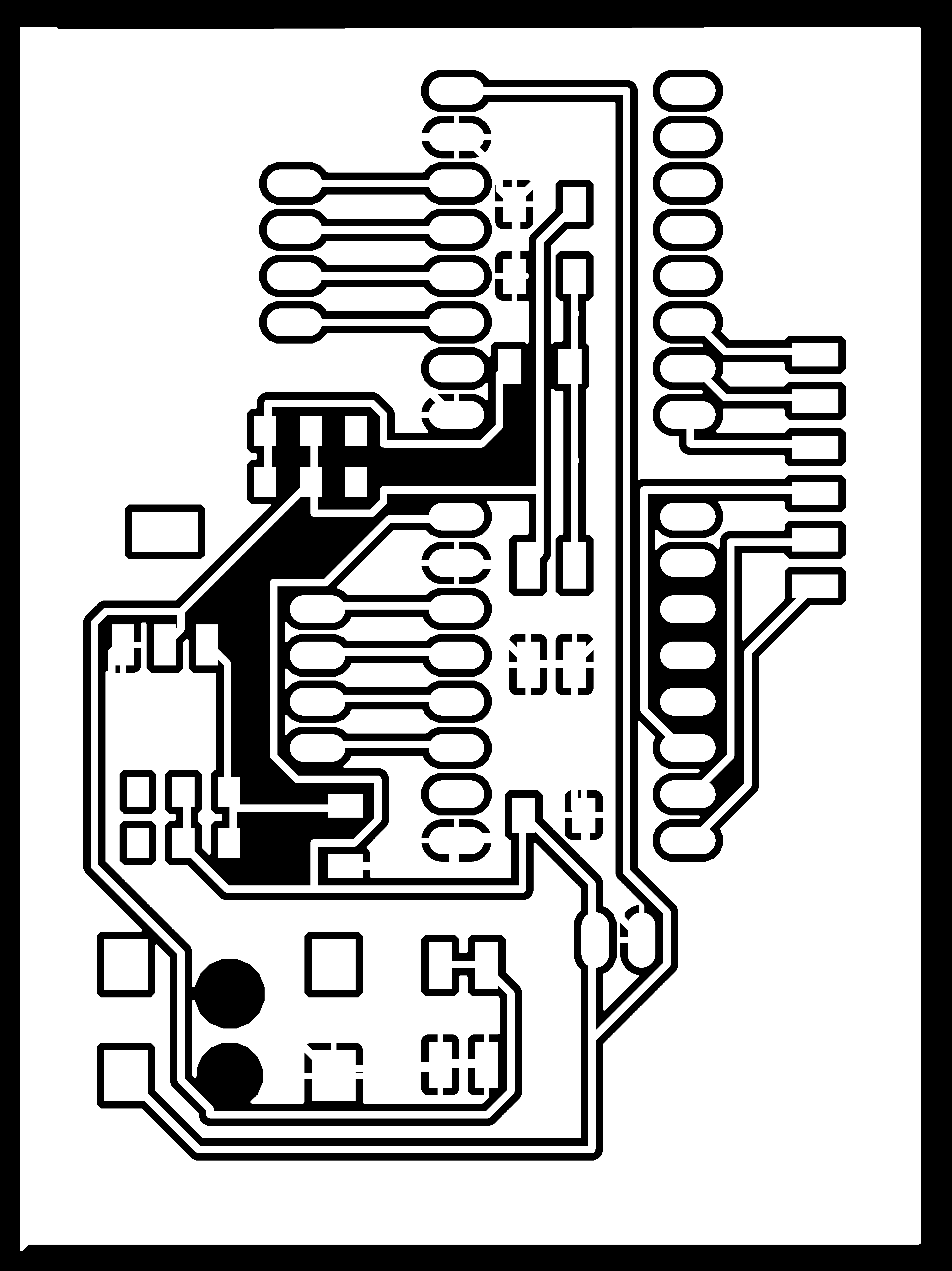
Motors Control Board
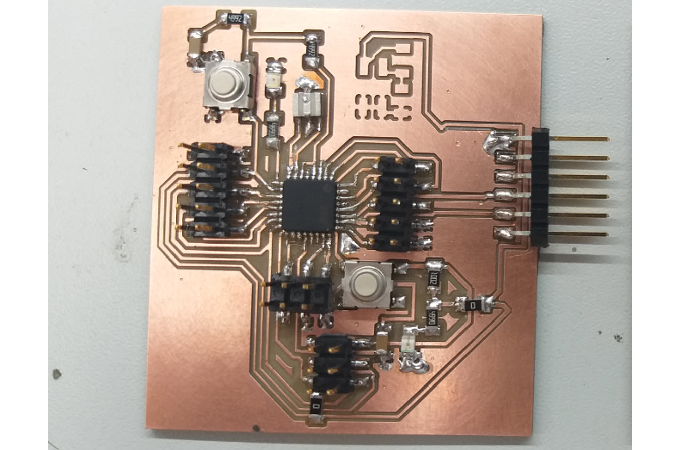
Testing the Main Board
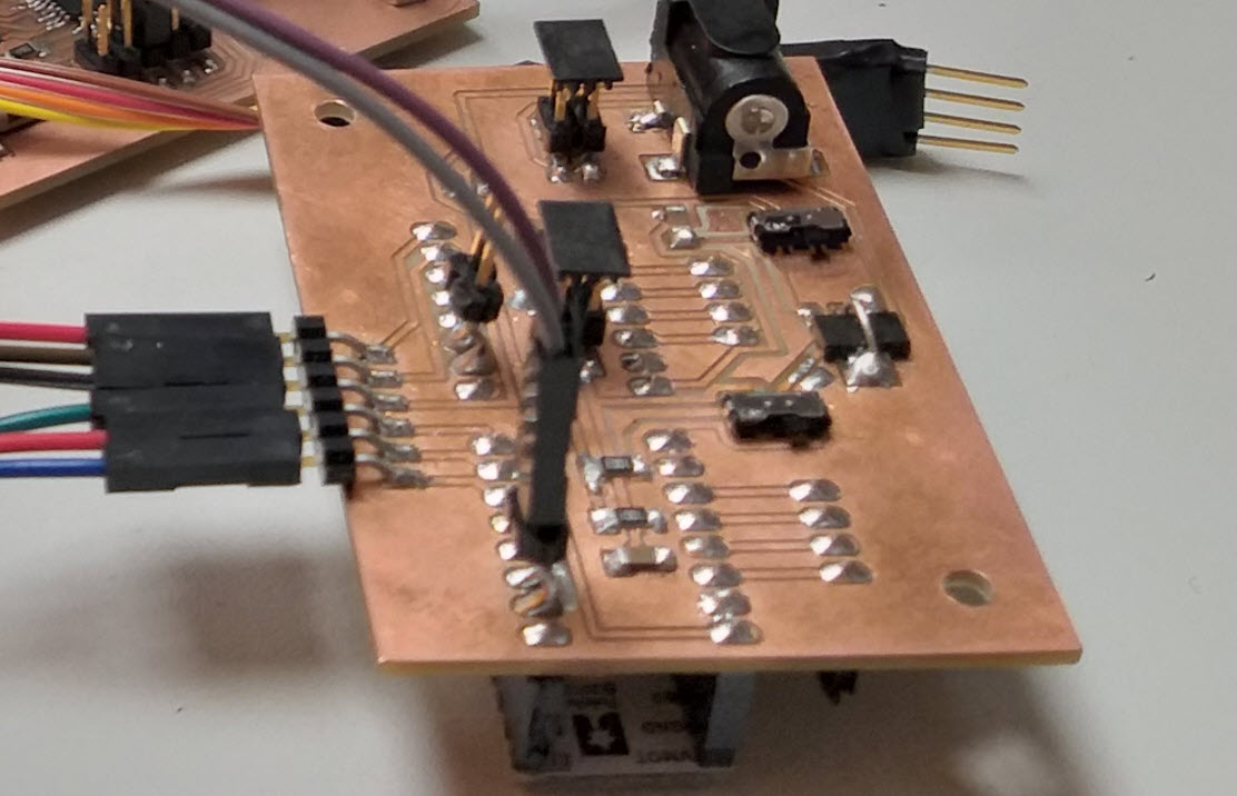
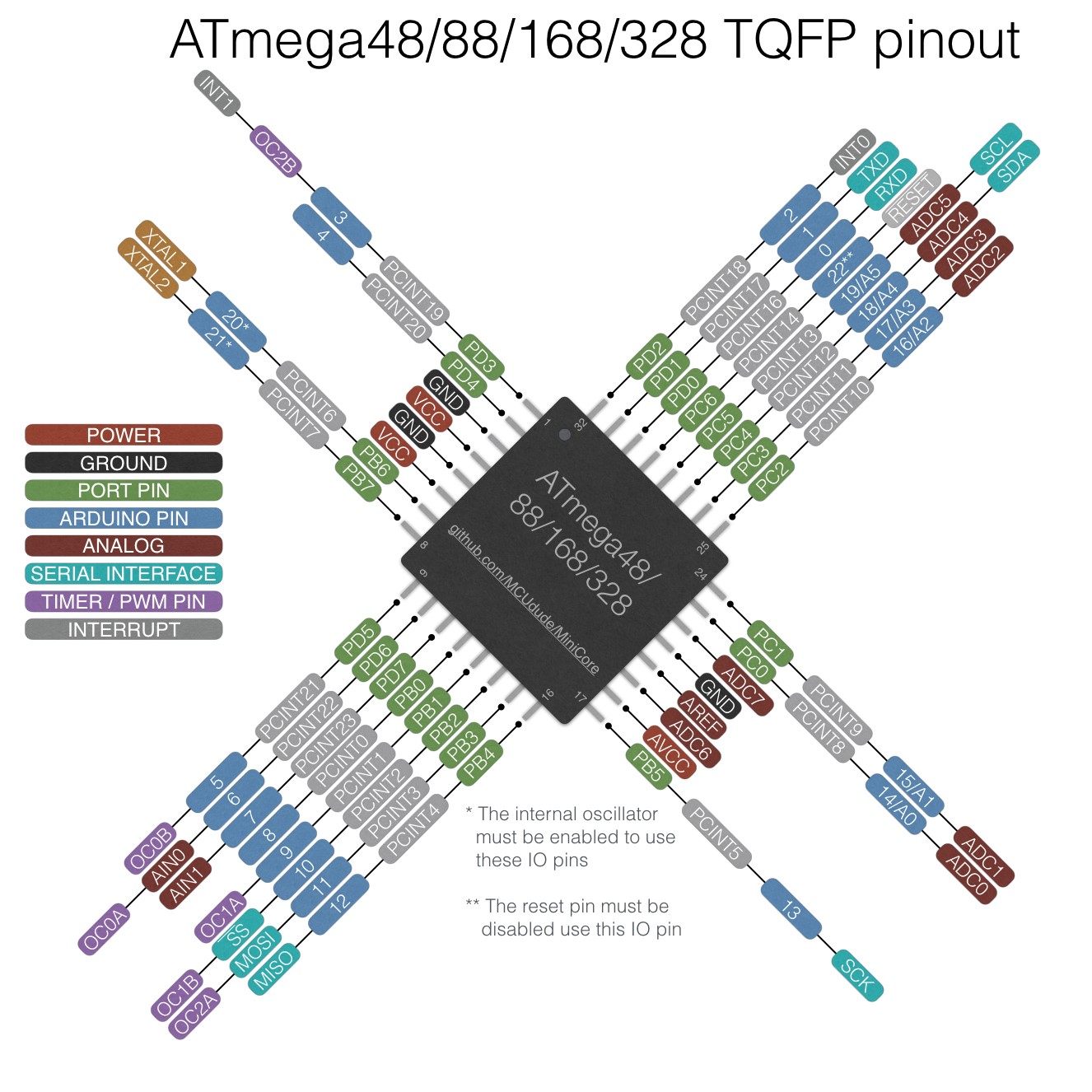
As I milled the Main Board, the next step was to perform testing inorder to know whethere the controller is working or not. I used by below picture to program the controller as per the pin configureations.
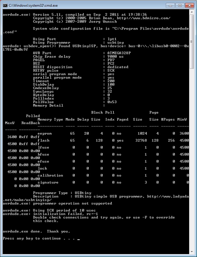
Unfortunely my controller was not working, I tried to upload a simple code to blink an LED but I was continuously getting the below error in the picture. I bricked my AVR somehow during burning bootloader I set something incorrectly and rewrote fuses.
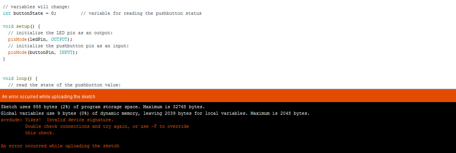
After continuous hours of struggle, I came to know that Lukasz Surazynski also suffered from similiar problem and the only way was to reprogrammed clock fuses in a way that it required 5V Peak-to-peak voltage with 1 MHz frequency (clock was still divided by 8) provided by the function generator at the XTAL1 pin of the ATMEGA328P. AVR Freaks Forum and This Blog were also helpful. Thanks to Lukasz, I was able to get my board back in working condition.
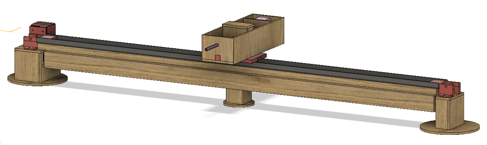
Mechanical Design Consideration and 3D Modelling
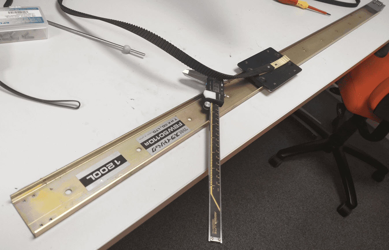
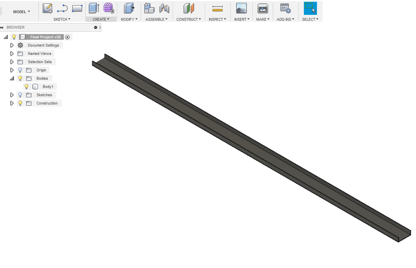
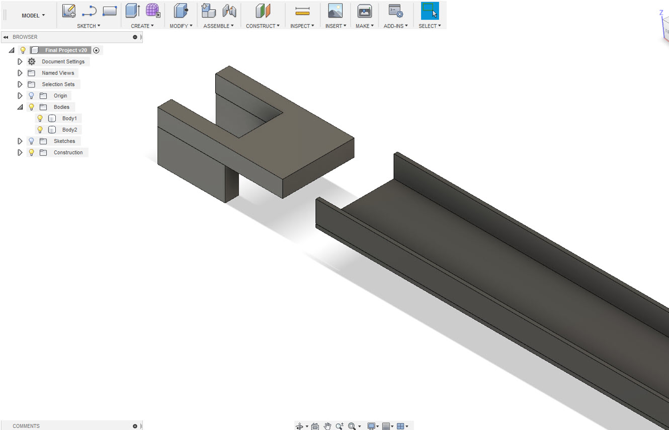
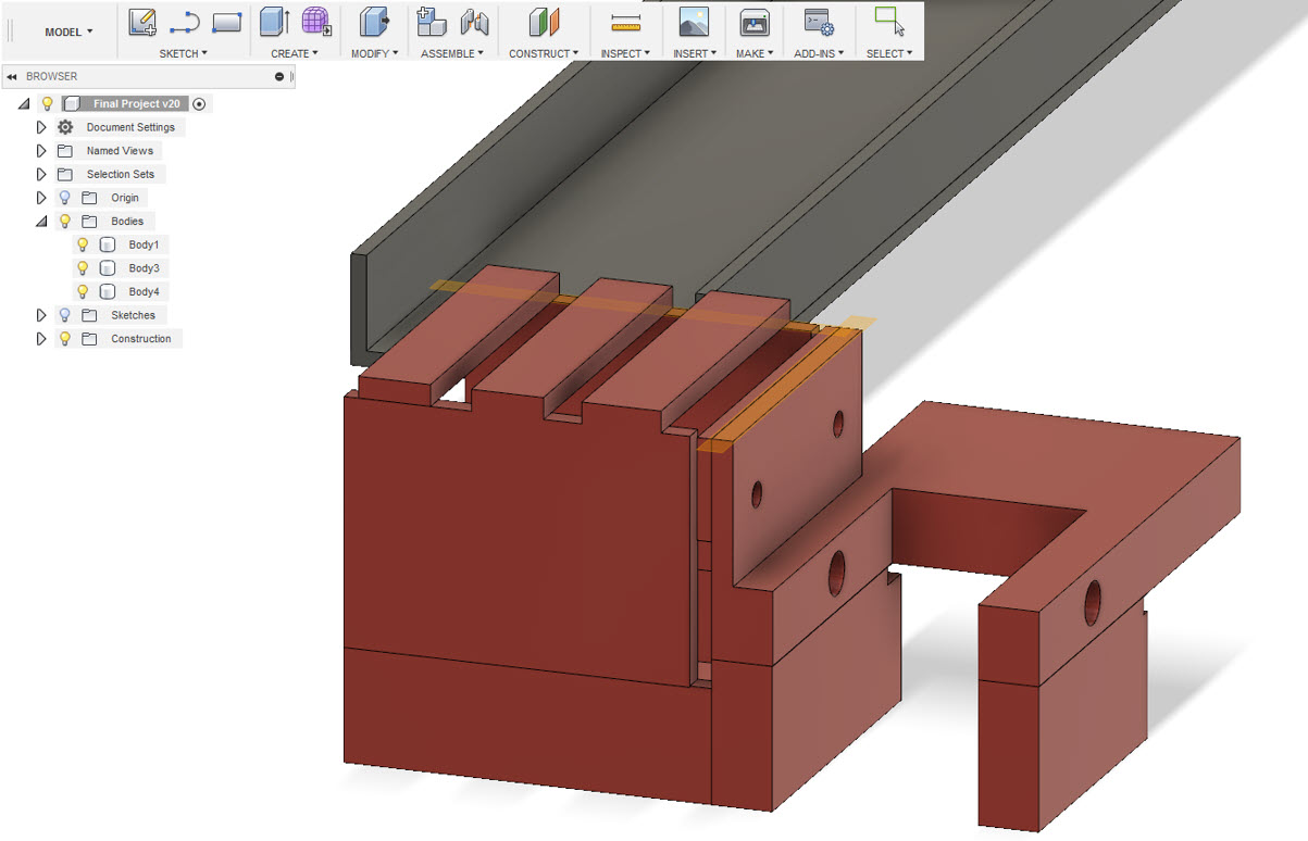
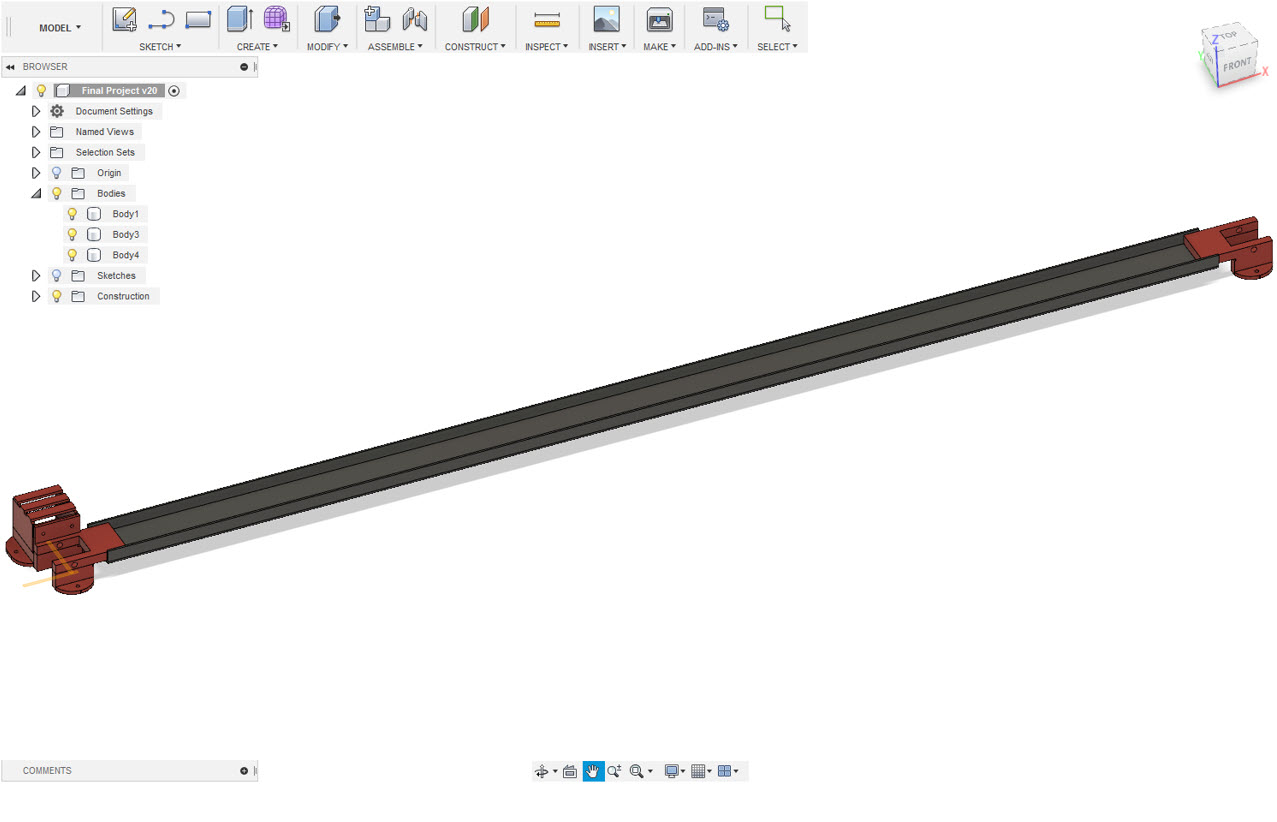
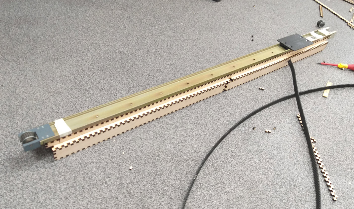
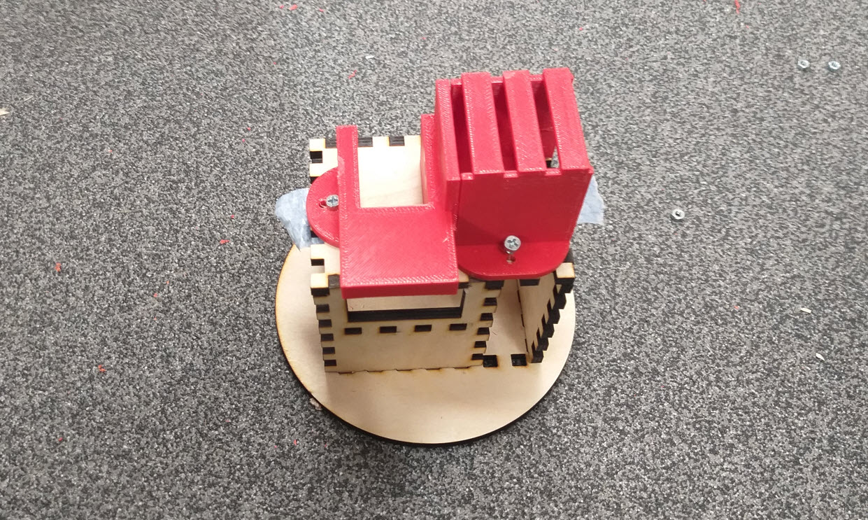
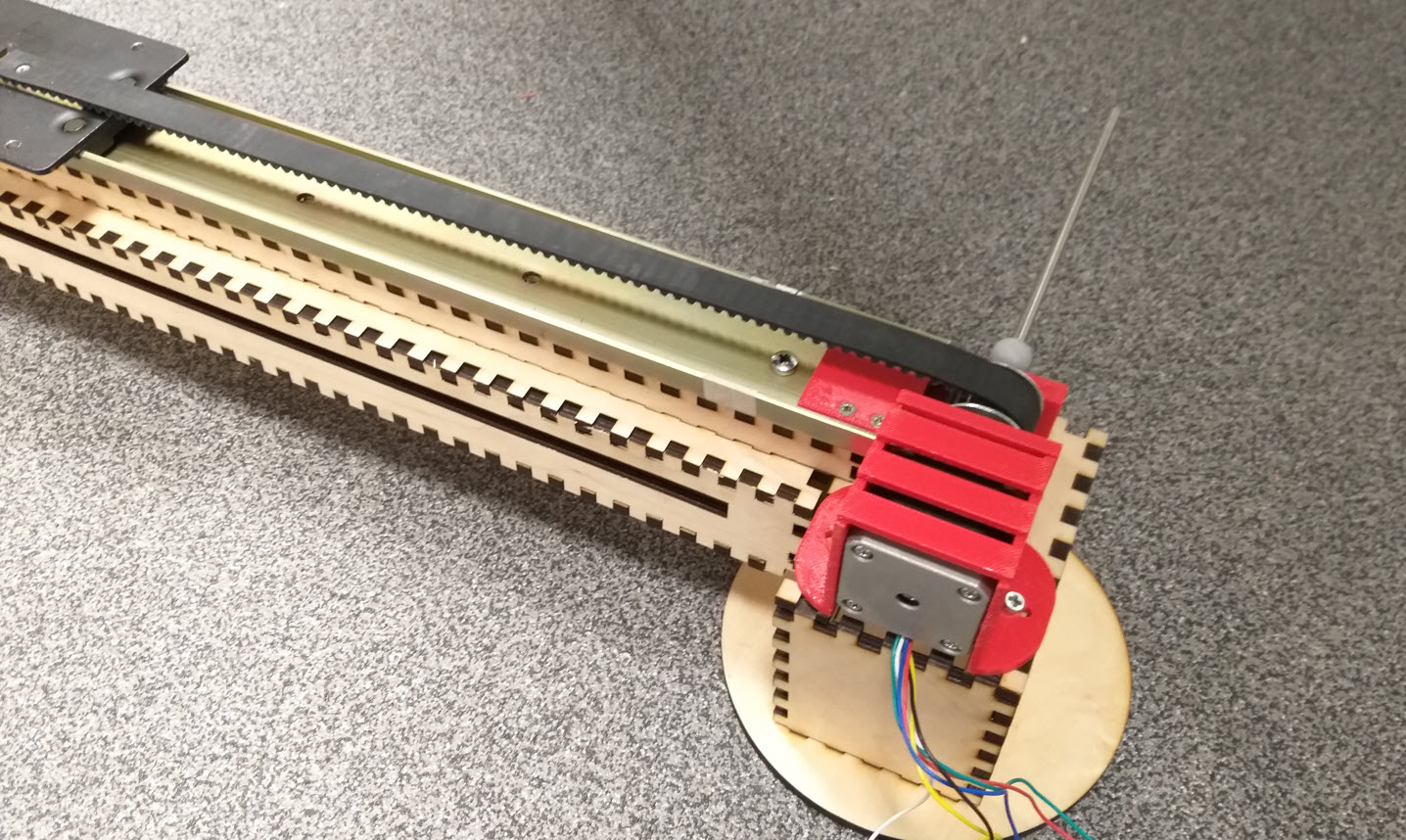
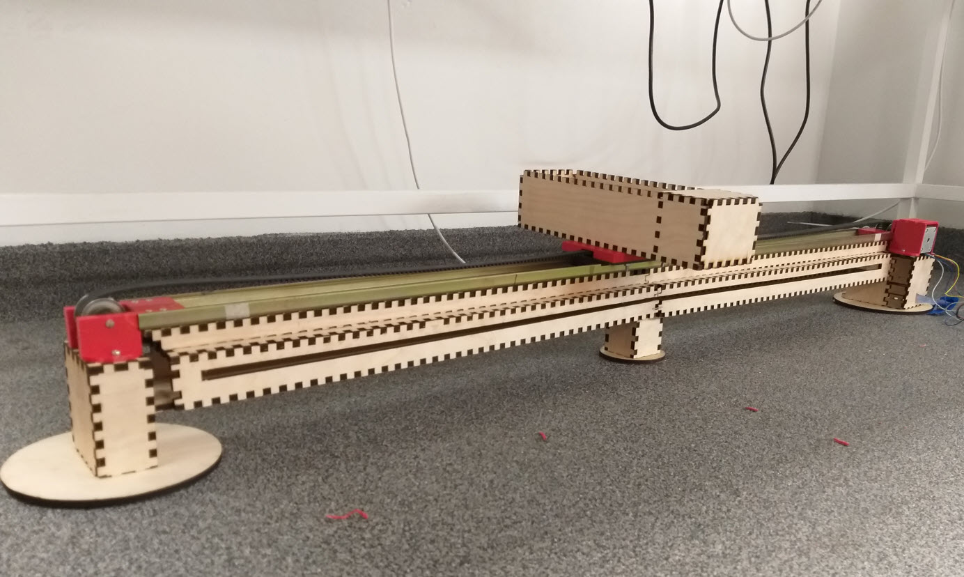
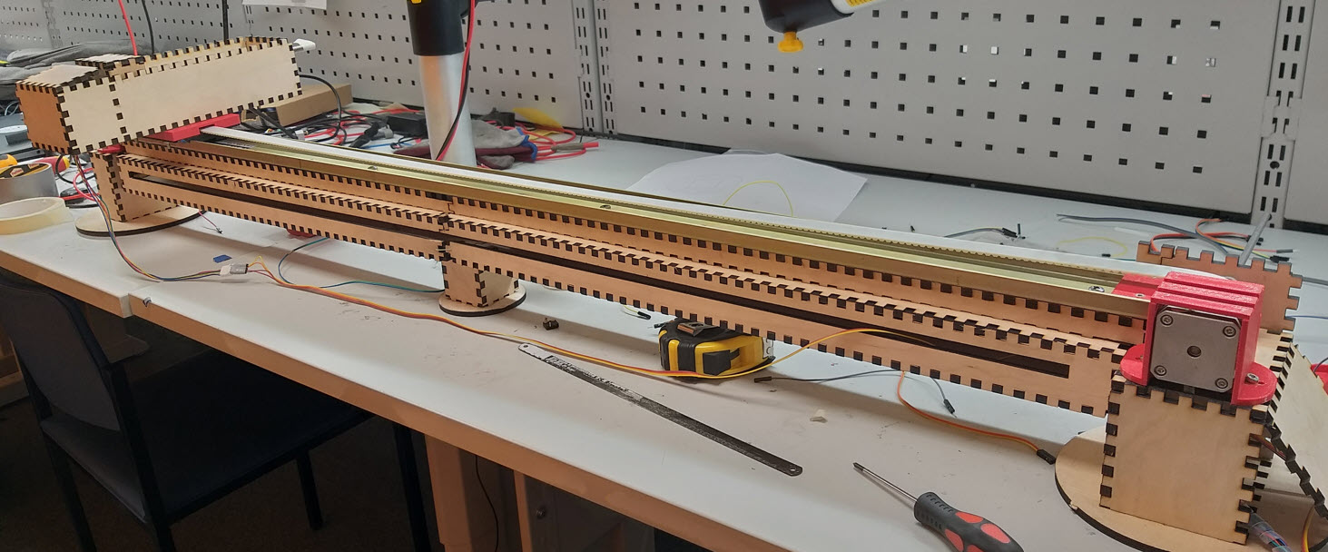
I decided to use 6mm Plywood material for my design. Also, I decided to 3D Print some of the parts thereby inorder to get the clear dimension of the designs I performed a complete 3D Model of my project. For this purpose, I utilized the knowledge of Week3 and Week6 to perform 3D Design. Initially I started with design of the Linear Rail for X Axis. I was using the Linear Guide Standard Ball Profile Rail - Series: FBW 50110XR for my X Axis, Fortunate enough to find it in the storage room with brackets in our FAB LAB. The X Axis has to be strong enough to withstand the weight. I got the dimensions and I initially started to design the X Axis. Then I decided to insert the brackets which I was willing to modify at each side of the rail as I would like to 3D print the brackers. At one end of the rail bracket, I decided to have the Stepper motor Space which will be tied to a pulley that will eventually drive the belt.
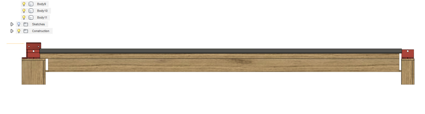
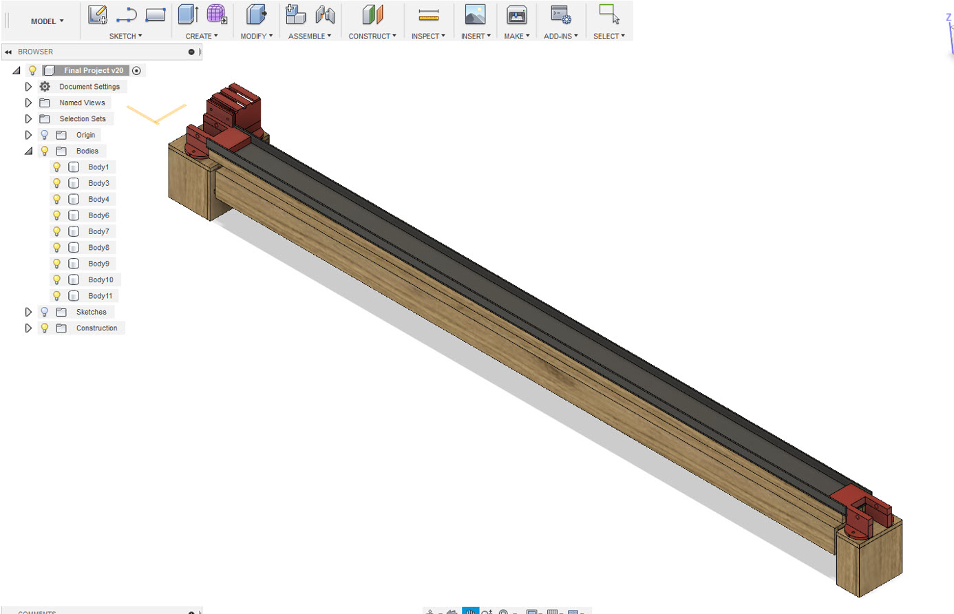
After the construction of the brackets and the rail, the next step was to build a foundation below which I thought to be of 6mm Plywood which will provide the best stablity to this X Axis. I considered the parameter value of Material Thickness to be 6mm.
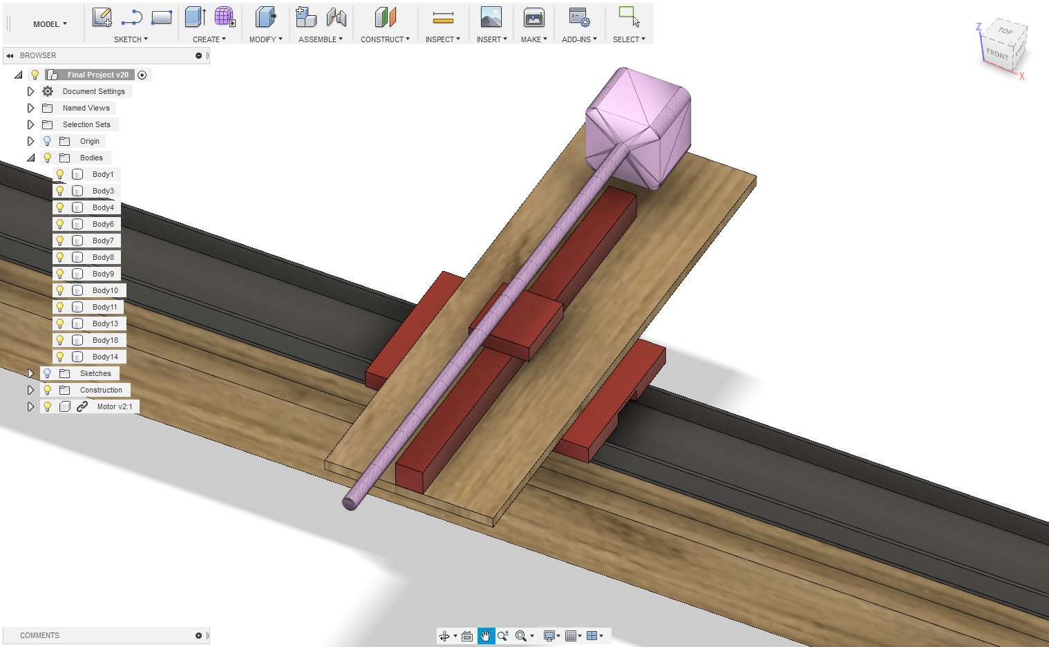
After the Construction of 3D Model of X_Axis, I designed the Y-Axis that will be placed on top of the Linear X Axis. As I was willing to use HG linear guide HGR25 width 23mm length 250mm for my design of Y Axis and was willing to use NEMA Stepper Motor with a Linear Screw thereby I designed according to the HC Linear Guide.
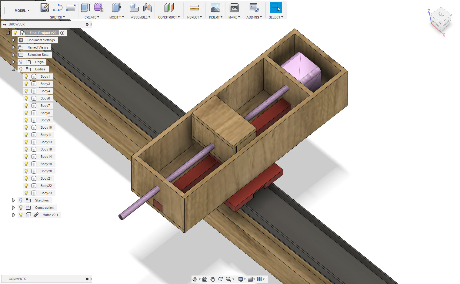
After the X and Y Axis was ready, I just added another wooden structure at the middle to provide more support to the Linear X-Axis Mechanism.
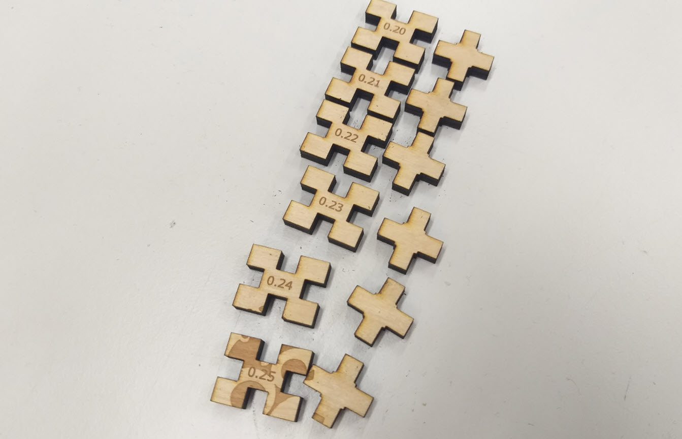
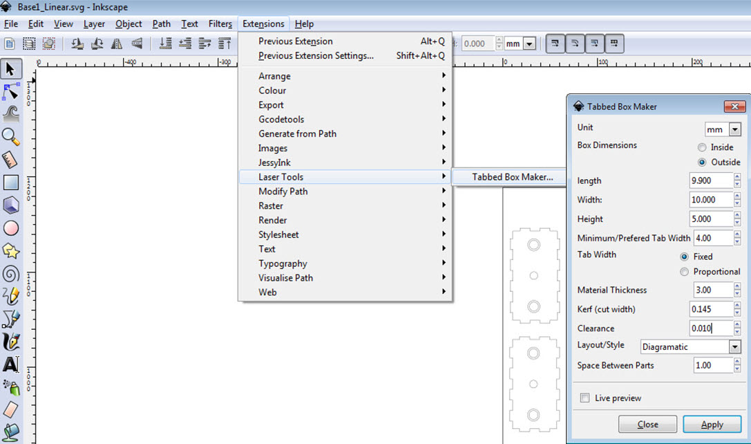
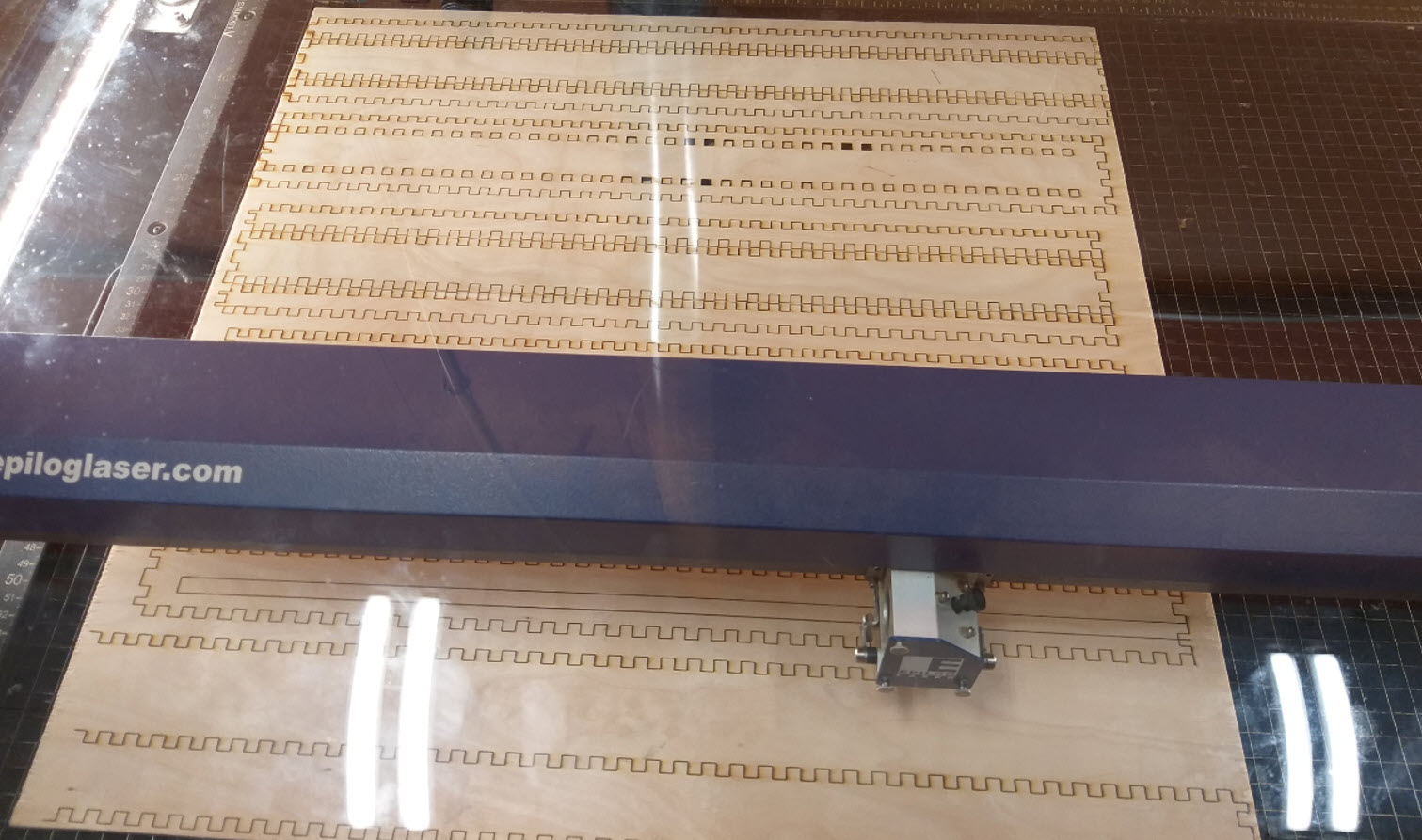
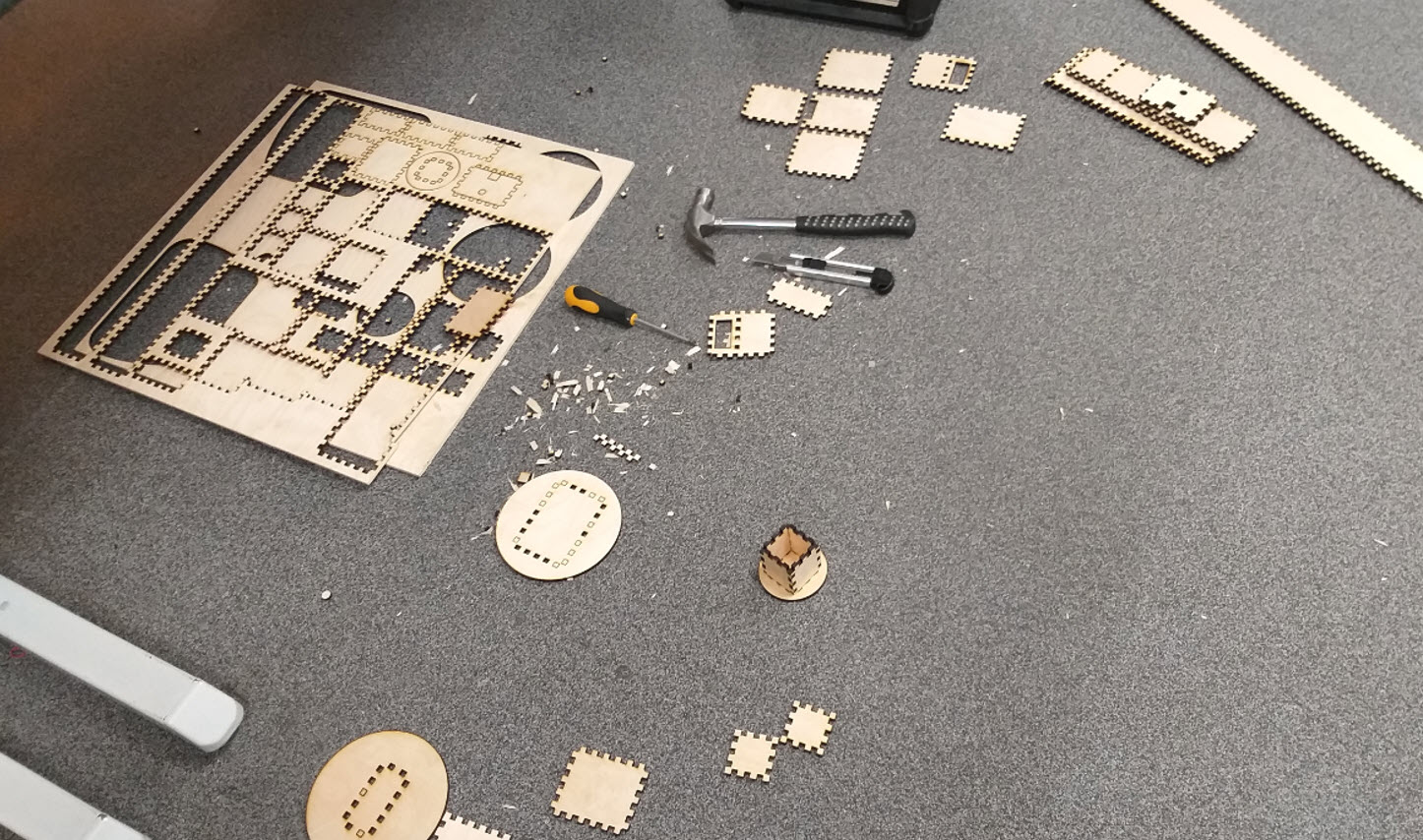
Laser Cutting
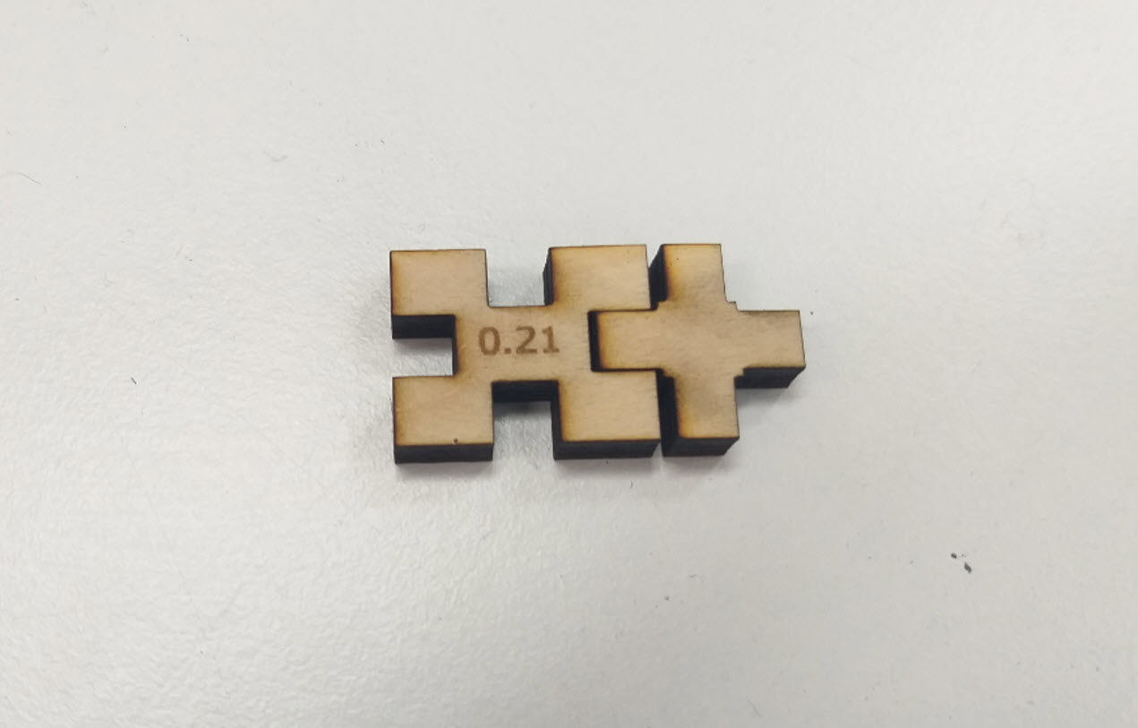
For Laser Cutting, I used the Tabbed Box Maker utility that is available in Inkscape and I got the corresponding dimension of width and length from the 3D Model that I created. Since I decided to use 6mm Plywood Material thereby to make a good pressfit, the value of kerf shall be known for this purpose I tried to find the value of kerf that was required for my design to have a nice press fit. I couple of Iterations, I found that the best value of kerf that would give me a good press fit for a 6mm plywood was 0.21
After getting the best pressfit, I used the Tabbed Box Maker utility to make the neccessary pressfit boxes for my design. For reference Week 4 gives details about the process of the Laser cutting.
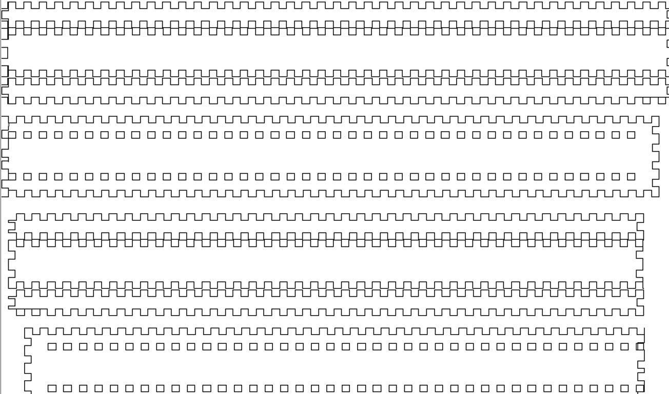
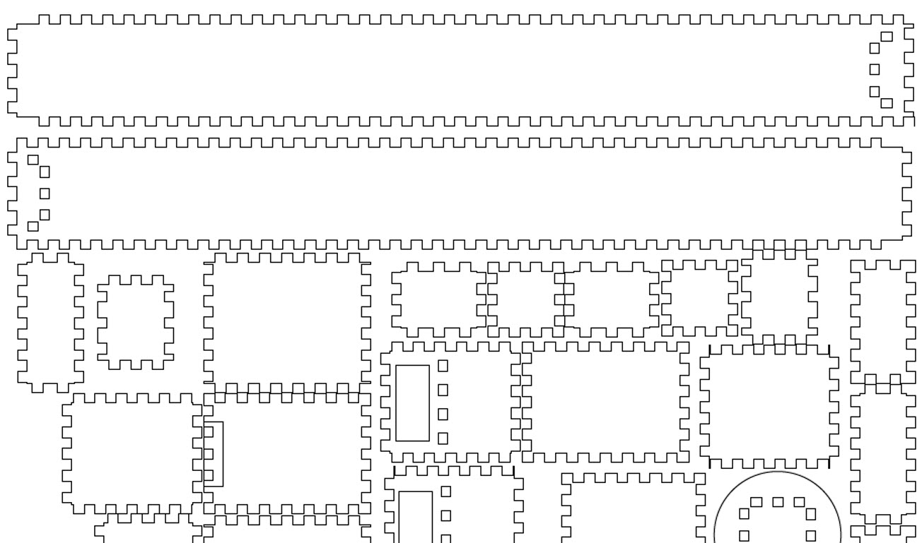
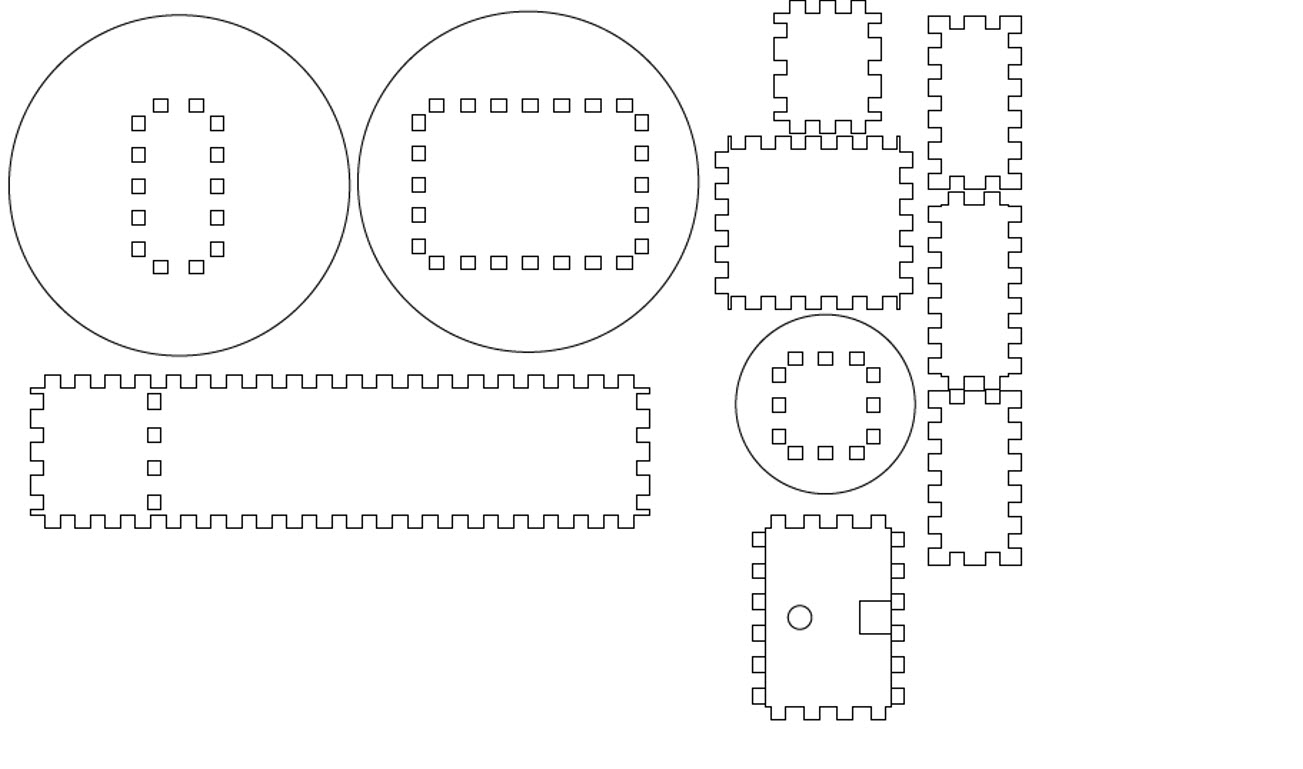
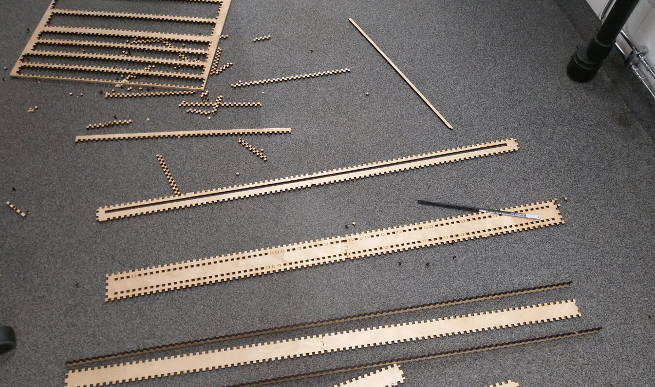
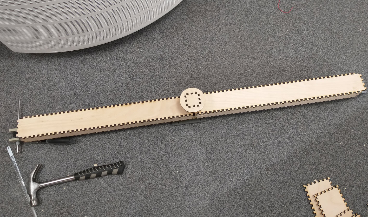
After Making the required design files, I Laser Cutted the required parts on the Laser Cutter. The press fit was tight enough and provided a rigid enough as I expected for my Structure to be rigid and strong enough.
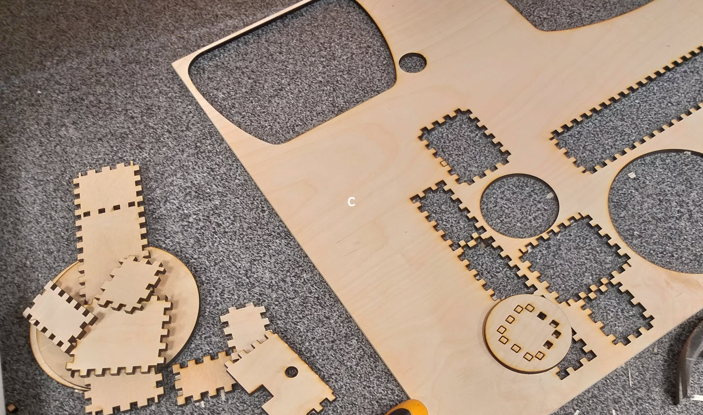
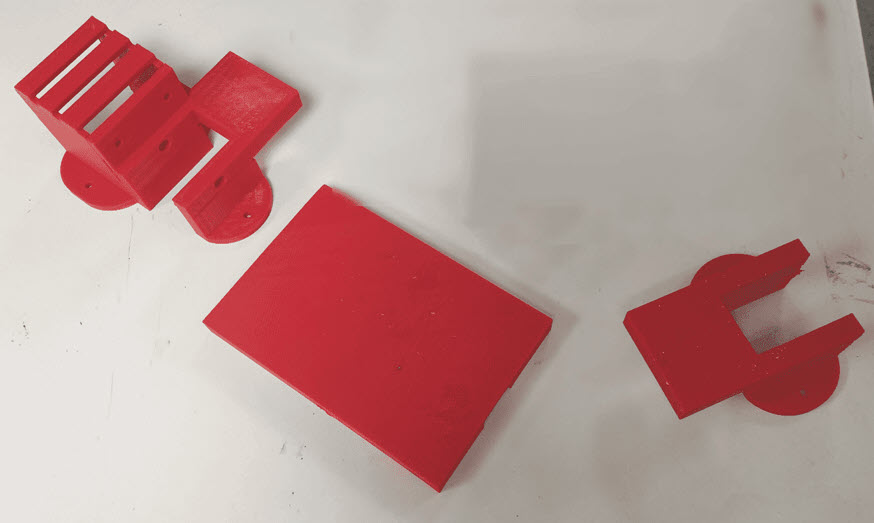
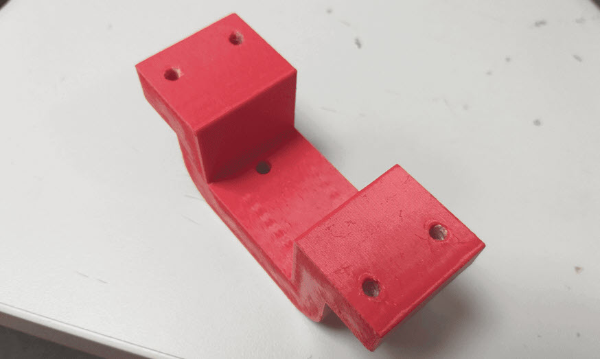
3D Printing
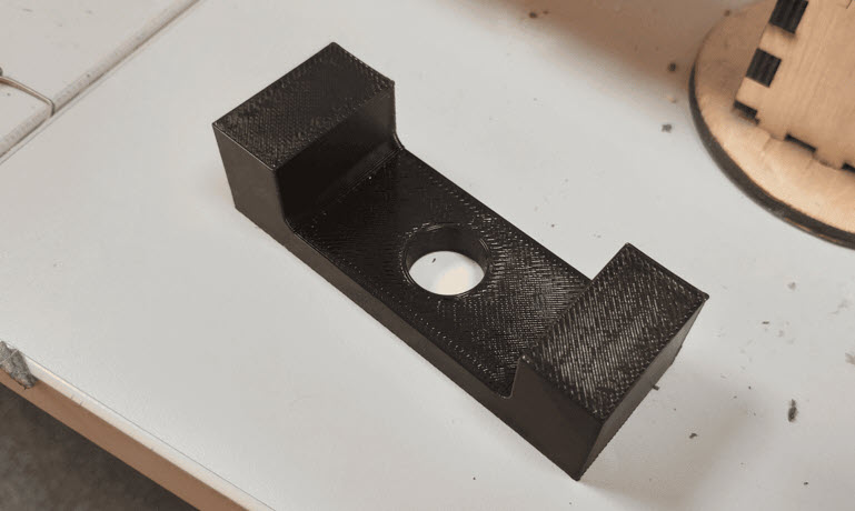
From the Main Design File, I extracted the STL Files for the Brackets and the Antenna Mount that I was willing to 3D Print and I 3D Printed those Parts. The Week 6 demonstrate the detail knowledge about 3D Printers.
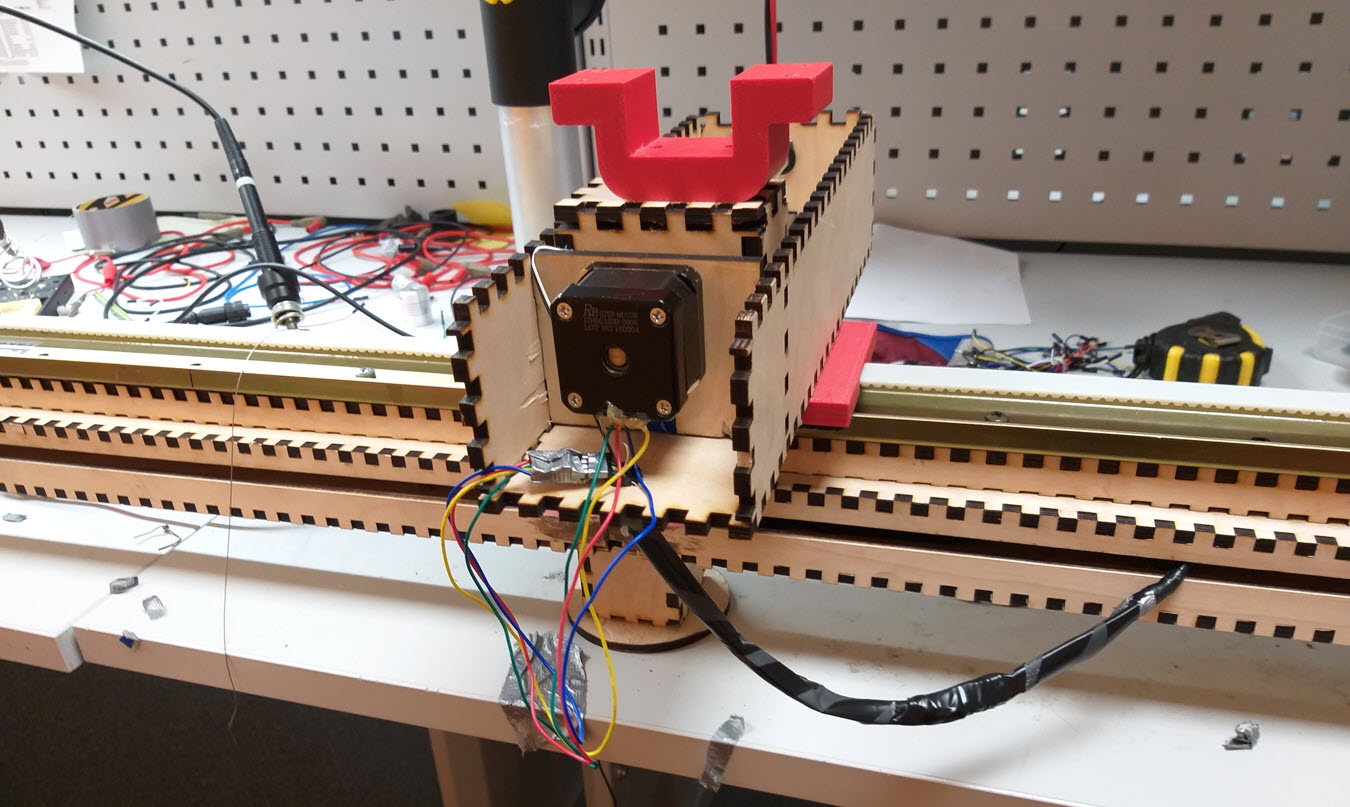
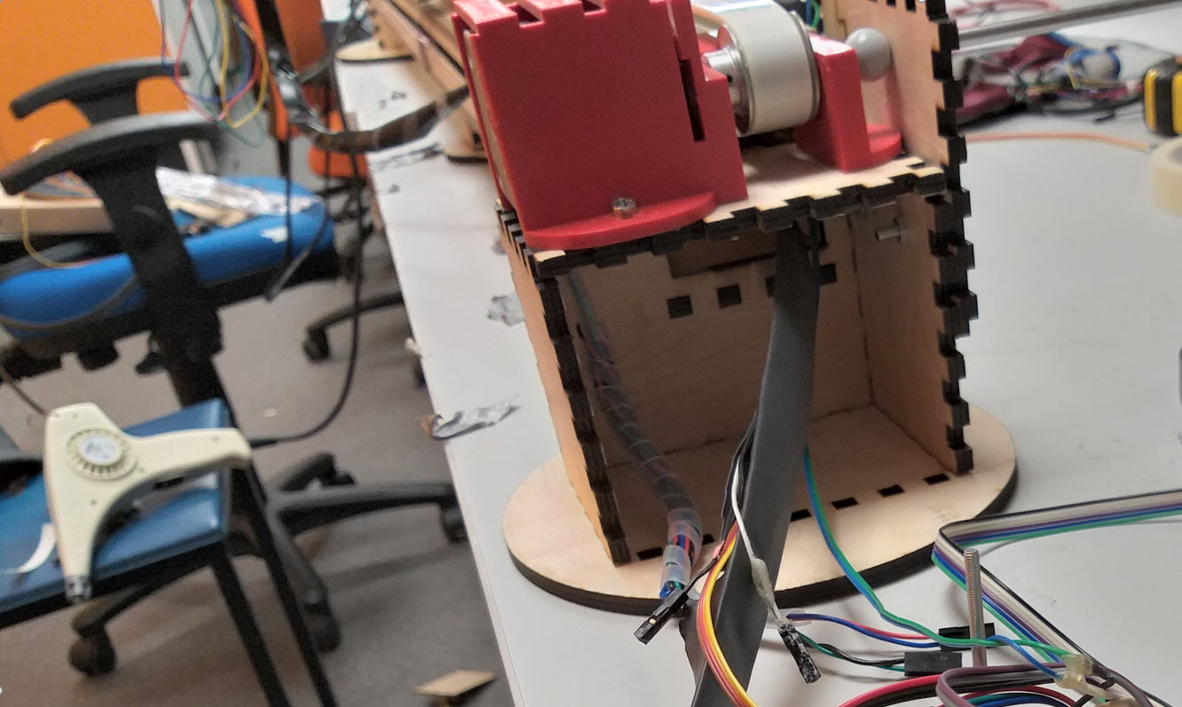
Assembling the Laser Cutted Parts, 3D Printed Parts and Wiring
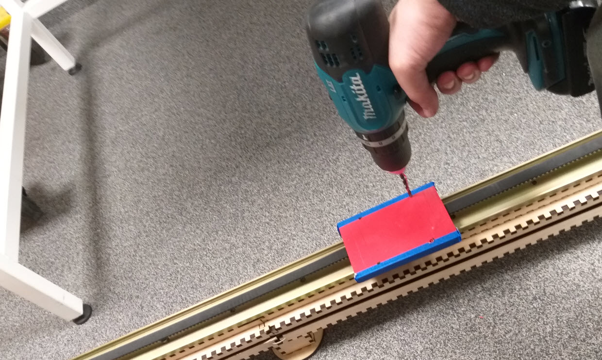
After Performing the Laser cutting and the 3D Printing, I tried to assemble the laser cutting and the 3D Printed parts all together. Plenty of Screws were required in this process and the Assembling took alot of time for me, to make it to perfection. The Wiring was the most difficult since I had to take care of wiring very careful inorder for it to provide no hurdle/entanglement in the Linear Motion Mechanism.
Embedded Programming
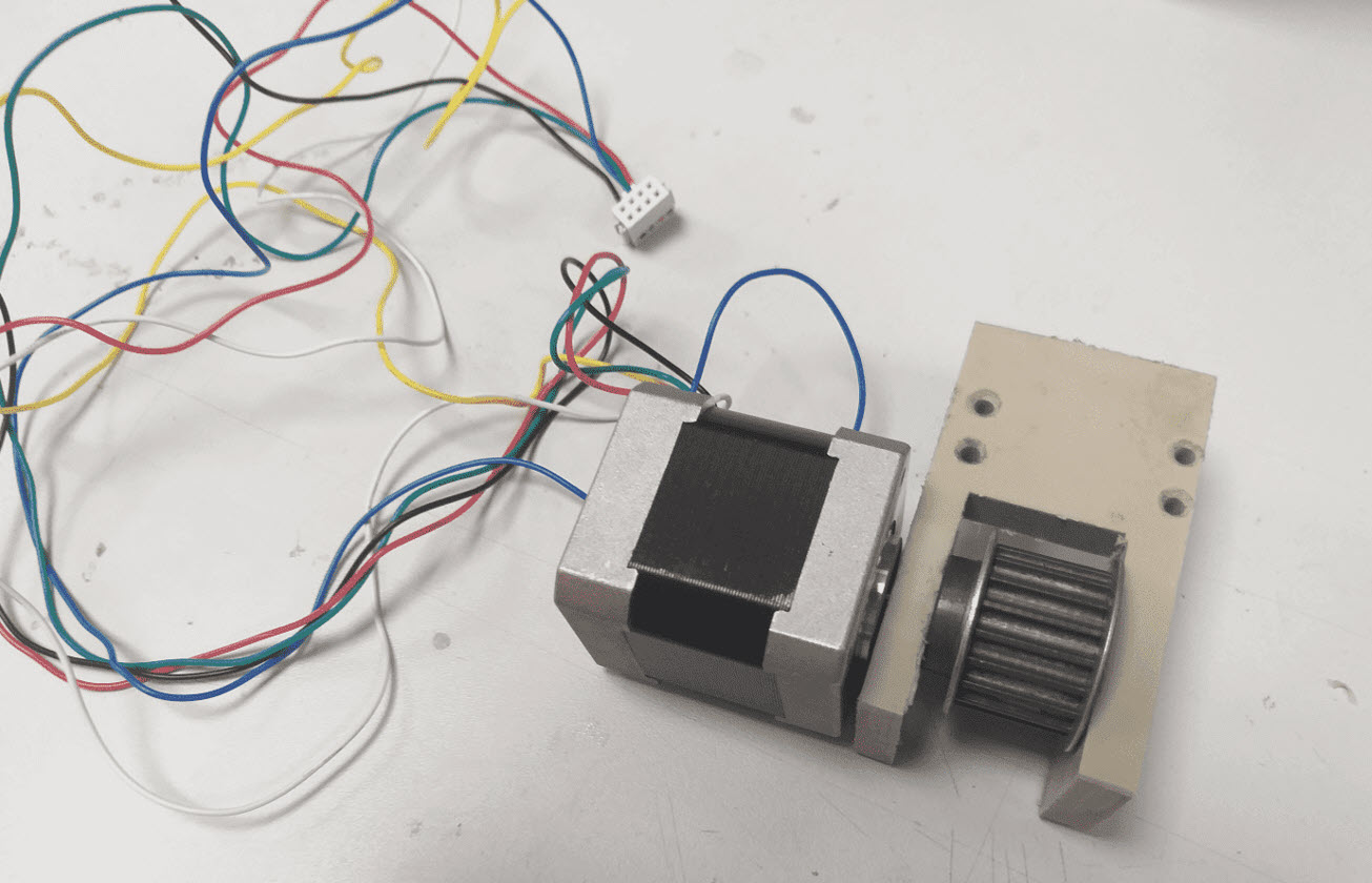
After Assembling the design and Manual checking the Mechanical design to be working fine. The next step was to Automate this process of Movement. I did the Programming early for stepper motors in Week 12 and had a pretty idea how the movement of the Motors work. Since I wanted to extract maximum torque from the Motors, I started looking for Libraries specifically related to DRV8834 Stepper Controller that can assist me to control the RPM of the Stepper Motor inorder to acquire maximum torque from the Linear X Axis. Fortunely, I was able to find a stepper motor control library with an example code that assisted me to perform the RPM Settings that suits my design for a smooth and powerful motion. The below link contains the example code
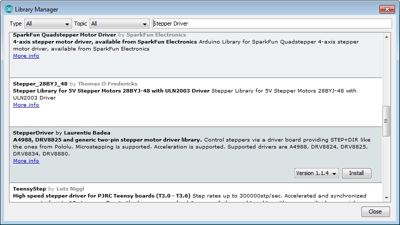
Since I require Maximum torque for my X Axis Mechanism since it had a timing belt along the 100cm length thereby I used the above mentioned Library for only X Axis. For the Y Axis, since it utilizes the Linear Screw Stepper and by giving the number of steps, the motion is quite and with good torque thereby I utilized the Week 12 code for that purpose.
/*
Microstepping demo
This requires that microstep control pins be connected in addition to STEP,DIR
Copyright (C)2015 Laurentiu Badea
Modified By: Yasir Shafiullah
This file may be redistributed under the terms of the MIT license.
A copy of this license has been included with this distribution in the file LICENSE.
*/
#include
// MOTOR 1 (X Axis)
// Motor steps per revolution. Most steppers are 200 steps or 1.8 degrees/step
#define MOTOR_STEPS 200
#define MOTOR_STEPS_MOVE 20
#define MOTOR_STEPS_MOVE_STOP 8
#define RPM 30
#define DIR 3
#define STEP 4
#define SLEEP 2 // optional (just delete SLEEP from everywhere if not used)
#include
#define txPin 12     // PA0(MISO) transmit signal to the bridge
#define rxPin 13    // PA1(SCK) recieves signal from bridge
SoftwareSerial mySerial(rxPin, txPin);
/*
Choose one of the sections below that match your board
*/
#include "DRV8834.h"
#define M0 7
#define M1 8
DRV8834 stepper(MOTOR_STEPS, DIR, STEP, SLEEP, M0, M1);
DRV8834 steppermove(MOTOR_STEPS_MOVE, DIR, STEP, SLEEP, M0, M1);
char Incoming_value = 0;                //Variable for storing Incoming_value
char Incoming_storage_move = 0;          //Variable for storing Incoming_value
const int buttonPinx = 15;
int buttonStatex;
// #include "A4988.h"
// #define MS1 10
// #define MS2 11
// #define MS3 12
// A4988 stepper(MOTOR_STEPS, DIR, STEP, SLEEP, MS1, MS2, MS3);
// #include "DRV8825.h"
// #define MODE0 10
// #define MODE1 11
// #define MODE2 12
// DRV8825 stepper(MOTOR_STEPS, DIR, STEP, SLEEP, MODE0, MODE1, MODE2);
// #include "DRV8880.h"
// #define M0 10
// #define M1 11
// #define TRQ0 6
// #define TRQ1 7
// DRV8880 stepper(MOTOR_STEPS, DIR, STEP, SLEEP, M0, M1, TRQ0, TRQ1);
// #include "BasicStepperDriver.h" // generic
// BasicStepperDriver stepper(DIR, STEP);
// MOTOR 2 (Y Axis)
#include
const int dirPin = 16;
const int stePin = 17;
const int sleePin = 18;
const int buttonPiny = 14;
int buttonStatey;
void setup() {
mySerial.begin(9600);         //Sets the data rate in bits per second (baud) for serial data transmission
pinMode(txPin, INPUT);   //default tx as input
pinMode(5, OUTPUT);        //Sets digital pin 8 as output pin
/*
Set target motor RPM.
*/
// if using enable/disable on ENABLE pin (active LOW) instead of SLEEP uncomment next line
// stepper.setEnableActiveState(LOW);
// set current level (for DRV8880 only).
// Valid percent values are 25, 50, 75 or 100.
// stepper.setCurrent(100);
//Motor 1 (X Axis)
// initialize the pushbutton pin as an input:
pinMode(buttonPinx, INPUT);
//Motor 2 (Y Axis)
pinMode(stePin, OUTPUT);
pinMode(dirPin, OUTPUT);
pinMode(sleePin, OUTPUT);
// initialize the pushbutton pin as an input:
pinMode(buttonPiny, INPUT);
}
void loop()
{
if (mySerial.available() > 0)
{
Incoming_value = mySerial.read();      //Read the incoming data and store it into variable Incoming_value
mySerial.print(Incoming_value);        //Print Value of Incoming_value in Serial monitor
mySerial.print("\n");        //New line
if (Incoming_value == 'A')           //Checks whether value of Incoming_value is equal to A
{
stepper.begin(RPM);
stepper.enable();
motor4();
}
else if (Incoming_value == 'B')           //Checks whether value of Incoming_value is equal to B
{
stepper.begin(RPM);
stepper.enable();
motor8();
}
else if (Incoming_value == 'C')           //Checks whether value of Incoming_value is equal to C
{
stepper.begin(RPM);
stepper.enable();
motor12();
}
else if (Incoming_value == 'D')           //Checks whether value of Incoming_value is equal to D
{
stepper.begin(RPM);
stepper.enable();
motor16();
}
else if (Incoming_value == 'E')           //Checks whether value of Incoming_value is equal to E
{
stepper.begin(RPM);
stepper.enable();
motor20();
}
else if (Incoming_value == 'F')           //Checks whether value of Incoming_value is equal to F
{
stepper.begin(RPM);
stepper.enable();
motor24();
}
else if (Incoming_value == 'G')           //Checks whether value of Incoming_value is equal to G
{
stepper.begin(RPM);
stepper.enable();
motor28();
}
else if (Incoming_value == 'H')           //Checks whether value of Incoming_value is equal to H
{
stepper.begin(RPM);
stepper.enable();
motor32();
}
else if (Incoming_value == 'I')           //Checks whether value of Incoming_value is equal to I
{
stepper.begin(RPM);
stepper.enable();
motor36();
}
else if (Incoming_value == 'J')           //Checks whether value of Incoming_value is equal to J
{
stepper.begin(RPM);
stepper.enable();
motor40();
}
else if (Incoming_value == 'K')           //Checks whether value of Incoming_value is equal to K
{
stepper.begin(RPM);
stepper.enable();
motor44();
}
else if (Incoming_value == 'L')           //Checks whether value of Incoming_value is equal to L
{
stepper.begin(RPM);
stepper.enable();
motor48();
}
else if (Incoming_value == 'M')           //Checks whether value of Incoming_value is equal to M
{
stepper.begin(RPM);
stepper.enable();
motor52();
}
else if (Incoming_value == 'N')           //Checks whether value of Incoming_value is equal to N
{
stepper.begin(RPM);
stepper.enable();
motor56();
}
else if (Incoming_value == 'O')           //Checks whether value of Incoming_value is equal to O
{
stepper.begin(RPM);
stepper.enable();
motor60();
}
else if (Incoming_value == 'P')           //Checks whether value of Incoming_value is equal to P
{
stepper.begin(RPM);
stepper.enable();
motor64();
}
else if (Incoming_value == 'Q')           //Checks whether value of Incoming_value is equal to Q
{
stepper.begin(RPM);
stepper.enable();
motor68();
}
else if (Incoming_value == 'R')           //Checks whether value of Incoming_value is equal to R
{
stepper.begin(RPM);
stepper.enable();
motor72();
}
else if (Incoming_value == 'S')           //Checks whether value of Incoming_value is equal to S
{
stepper.begin(RPM);
stepper.enable();
motor76();
}
else if (Incoming_value == 'T')           //Checks whether value of Incoming_value is equal to T
{
stepper.begin(RPM);
stepper.enable();
motor80();
}
else if (Incoming_value == 'U')           //Checks whether value of Incoming_value is equal to U
{
stepper.begin(RPM);
stepper.enable();
motor84();
}
else if (Incoming_value == 'V')           //Checks whether value of Incoming_value is equal to V
{
stepper.begin(RPM);
stepper.enable();
motor88();
}
else if (Incoming_value == 'W')           //Checks whether value of Incoming_value is equal to W
{
steppermove.begin(170);
steppermove.enable();
Incoming_storage_move=Incoming_value;
motorforward();
}
else if (Incoming_value == 'X')           //Checks whether value of Incoming_value is equal to X
{
steppermove.begin(170);
steppermove.enable();
Incoming_storage_move=Incoming_value;
motorbackward();
}
else if (Incoming_value == 'Y')           //Checks whether value of Incoming_value is equal to Y
{
Incoming_storage_move=Incoming_value;
digitalWrite(sleePin, HIGH);
digitalWrite(dirPin, LOW);
motorleft();
}
else if (Incoming_value == 'Z')           //Checks whether value of Incoming_value is equal to Z
{
Incoming_storage_move=Incoming_value;
digitalWrite(sleePin, HIGH);
digitalWrite(dirPin, HIGH);
motorright();
}
else if (Incoming_value == '1')           //Checks whether value of Incoming_value is equal to 1
{
Incoming_storage_move=Incoming_value;
digitalWrite(sleePin, HIGH);
digitalWrite(dirPin, HIGH);
motor_b3cm();
}
else if (Incoming_value == '2')           //Checks whether value of Incoming_value is equal to 2
{
Incoming_storage_move=Incoming_value;
digitalWrite(sleePin, HIGH);
digitalWrite(dirPin, HIGH);
motor_b6cm();
}
else if (Incoming_value == '3')           //Checks whether value of Incoming_value is equal to 3
{
Incoming_storage_move=Incoming_value;
digitalWrite(sleePin, HIGH);
digitalWrite(dirPin, HIGH);
motor_b9cm();
}
else if (Incoming_value == '4')           //Checks whether value of Incoming_value is equal to 4
{
Incoming_storage_move=Incoming_value;
digitalWrite(sleePin, HIGH);
digitalWrite(dirPin, HIGH);
motor_b12cm();
}
else if (Incoming_value == '5')           //Checks whether value of Incoming_value is equal to 5
{
Incoming_storage_move=Incoming_value;
digitalWrite(sleePin, HIGH);
digitalWrite(dirPin, HIGH);
motor_b15cm();
}
else if (Incoming_value == '6')           //Checks whether value of Incoming_value is equal to 6
{
Incoming_storage_move=Incoming_value;
digitalWrite(sleePin, HIGH);
digitalWrite(dirPin, LOW);
motorleft();
steppermove.begin(170);
steppermove.enable();
motororigin();
}
}
}
void motor4() {
digitalWrite(5, LOW);
stepper.setMicrostep(1);  // Set microstep mode to 1:1
stepper.rotate(190.98);     // forward revolution
}
void motor8() {
digitalWrite(5, LOW);
stepper.setMicrostep(1);  // Set microstep mode to 1:1
stepper.rotate(381.96);     // forward revolution
}
void motor12() {
digitalWrite(5, LOW);
stepper.setMicrostep(1);  // Set microstep mode to 1:1
stepper.rotate(572.94);     // forward revolution
}
void motor16() {
digitalWrite(5, LOW);
stepper.setMicrostep(1);  // Set microstep mode to 1:1
stepper.rotate(763.92);     // forward revolution
}
void motor20() {
digitalWrite(5, LOW);
stepper.setMicrostep(1);  // Set microstep mode to 1:1
stepper.rotate(954.9);     // forward revolution
}
void motor24() {
digitalWrite(5, LOW);
stepper.setMicrostep(1);  // Set microstep mode to 1:1
stepper.rotate(1145.88);     // forward revolution
}
void motor28() {
digitalWrite(5, LOW);
stepper.setMicrostep(1);  // Set microstep mode to 1:1
stepper.rotate(1336.86);     // forward revolution
}
void motor32() {
digitalWrite(5, LOW);
stepper.setMicrostep(1);  // Set microstep mode to 1:1
stepper.rotate(1527.84);     // forward revolution
}
void motor36() {
digitalWrite(5, LOW);
stepper.setMicrostep(1);  // Set microstep mode to 1:1
stepper.rotate(1718.82);     // forward revolution
}
void motor40() {
digitalWrite(5, LOW);
stepper.setMicrostep(1);  // Set microstep mode to 1:1
stepper.rotate(1909.8);     // forward revolution
}
void motor44() {
digitalWrite(5, LOW);
stepper.setMicrostep(1);  // Set microstep mode to 1:1
stepper.rotate(2100.78);     // forward revolution
}
void motor48() {
digitalWrite(5, LOW);
stepper.setMicrostep(1);  // Set microstep mode to 1:1
stepper.rotate(2291.76);     // forward revolution
}
void motor52() {
digitalWrite(5, LOW);
stepper.setMicrostep(1);  // Set microstep mode to 1:1
stepper.rotate(2482.74);     // forward revolution
}
void motor56() {
digitalWrite(5, LOW);
stepper.setMicrostep(1);  // Set microstep mode to 1:1
stepper.rotate(2673.72);     // forward revolution
}
void motor60() {
digitalWrite(5, LOW);
stepper.setMicrostep(1);  // Set microstep mode to 1:1
stepper.rotate(2864.7);     // forward revolution
}
void motor64() {
digitalWrite(5, LOW);
stepper.setMicrostep(1);  // Set microstep mode to 1:1
stepper.rotate(3055.68);     // forward revolution
}
void motor68() {
digitalWrite(5, LOW);
stepper.setMicrostep(1);  // Set microstep mode to 1:1
stepper.rotate(3246.66);     // forward revolution
}
void motor72() {
digitalWrite(5, LOW);
stepper.setMicrostep(1);  // Set microstep mode to 1:1
stepper.rotate(3437.64);     // forward revolution
}
void motor76() {
digitalWrite(5, LOW);
stepper.setMicrostep(1);  // Set microstep mode to 1:1
stepper.rotate(3628.62);     // forward revolution
}
void motor80() {
digitalWrite(5, LOW);
stepper.setMicrostep(1);  // Set microstep mode to 1:1
stepper.rotate(3819.6);     // forward revolution
}
void motor84() {
digitalWrite(5, LOW);
stepper.setMicrostep(1);  // Set microstep mode to 1:1
stepper.rotate(4010.58);     // forward revolution
}
void motor88() {
digitalWrite(5, LOW);
stepper.setMicrostep(1);  // Set microstep mode to 1:1
stepper.rotate(4201.56);     // forward revolution
}
void motorforward() {
steppermove.setMicrostep(8);
while (Incoming_storage_move == 'W')  {
steppermove.move(8*MOTOR_STEPS_MOVE);
Incoming_value = mySerial.read();
if (Incoming_value == '0')
{
break;
}
else
{
steppermove.move(8*MOTOR_STEPS_MOVE);
}
}
digitalWrite(5, HIGH);
steppermove.disable();
}
void motorbackward() {
steppermove.setMicrostep(8);
while (Incoming_storage_move == 'X')  {
steppermove.move(-8*MOTOR_STEPS_MOVE);
Incoming_value = mySerial.read();
// read the state of the pushbutton value:
buttonStatex = digitalRead(buttonPinx);
if (Incoming_value == '0')
{
break;
}
else if (buttonStatex == HIGH)
{
break;
}
else
{
steppermove.move(-8*MOTOR_STEPS_MOVE);
}
}
steppermove.disable();
steppermove.begin(170);
steppermove.enable();
steppermove.setMicrostep(1);
steppermove.move(MOTOR_STEPS_MOVE/3);
digitalWrite(5, HIGH);
}
void motorleft() {
// read the state of the pushbutton value:
buttonStatey = digitalRead(buttonPiny);
while (buttonStatey == LOW) {
// read the state of the pushbutton value:
buttonStatey = digitalRead(buttonPiny);
digitalWrite(stePin, HIGH);
delayMicroseconds(200);
digitalWrite(stePin, LOW);
delayMicroseconds(150);
// read the state of the pushbutton value:
buttonStatey = digitalRead(buttonPiny);
Incoming_value = mySerial.read();
if (buttonStatey == HIGH)
{
break;
}
else if (Incoming_value == '0')
{
break;
}
}
digitalWrite(sleePin, HIGH);
digitalWrite(dirPin, HIGH);
for (int x = 0; x <200; x++) {
digitalWrite(stePin, HIGH);
delayMicroseconds(200);
digitalWrite(stePin, LOW);
delayMicroseconds(150);
}
digitalWrite(sleePin, LOW);
digitalWrite(5, HIGH);
}
void motorright() {
// read the state of the pushbutton value:
buttonStatey = digitalRead(buttonPiny);
while (buttonStatey == LOW) {
// read the state of the pushbutton value:
buttonStatey = digitalRead(buttonPiny);
digitalWrite(stePin, HIGH);
delayMicroseconds(200);
digitalWrite(stePin, LOW);
delayMicroseconds(150);
// read the state of the pushbutton value:
buttonStatey = digitalRead(buttonPiny);
Incoming_value = mySerial.read();
if (buttonStatey == HIGH)
{
break;
}
else if (Incoming_value == '0')
{
break;
}
}
digitalWrite(sleePin, HIGH);
digitalWrite(dirPin, LOW);
for (int x = 0; x <200; x++) {
digitalWrite(stePin, HIGH);
delayMicroseconds(200);
digitalWrite(stePin, LOW);
delayMicroseconds(150);
}
digitalWrite(sleePin, LOW);
digitalWrite(5, HIGH);
}
void motor_b3cm()
{
for (int x = 0; x <3000; x++) {
digitalWrite(stePin, HIGH);
delayMicroseconds(200);
digitalWrite(stePin, LOW);
delayMicroseconds(150);
// read the state of the pushbutton value:
buttonStatey = digitalRead(buttonPiny);
if (buttonStatey == HIGH)
{
break;
}
}
digitalWrite(sleePin, LOW);
digitalWrite(5, HIGH);
}
void motor_b6cm()
{
for (int x = 0; x <6000; x++) {
digitalWrite(stePin, HIGH);
delayMicroseconds(200);
digitalWrite(stePin, LOW);
delayMicroseconds(150);
// read the state of the pushbutton value:
buttonStatey = digitalRead(buttonPiny);
if (buttonStatey == HIGH)
{
break;
}
}
digitalWrite(sleePin, LOW);
digitalWrite(5, HIGH);
}
void motor_b9cm()
{
for (int x = 0; x <9000; x++) {
digitalWrite(stePin, HIGH);
delayMicroseconds(200);
digitalWrite(stePin, LOW);
delayMicroseconds(150);
// read the state of the pushbutton value:
buttonStatey = digitalRead(buttonPiny);
if (buttonStatey == HIGH)
{
break;
}
}
digitalWrite(sleePin, LOW);
digitalWrite(5, HIGH);
}
void motor_b12cm()
{
for (int x = 0; x <12000; x++) {
digitalWrite(stePin, HIGH);
delayMicroseconds(200);
digitalWrite(stePin, LOW);
delayMicroseconds(150);
// read the state of the pushbutton value:
buttonStatey = digitalRead(buttonPiny);
if (buttonStatey == HIGH)
{
break;
}
}
digitalWrite(sleePin, LOW);
digitalWrite(5, HIGH);
}
void motor_b15cm()
{
for (int x = 0; x <15000; x++) {
digitalWrite(stePin, HIGH);
delayMicroseconds(200);
digitalWrite(stePin, LOW);
delayMicroseconds(150);
// read the state of the pushbutton value:
buttonStatey = digitalRead(buttonPiny);
if (buttonStatey == HIGH)
{
break;
}
}
digitalWrite(sleePin, LOW);
digitalWrite(5, HIGH);
}
void motororigin() {
steppermove.setMicrostep(8);
while (Incoming_storage_move == '6')  {
steppermove.move(-8*MOTOR_STEPS_MOVE);
Incoming_value = mySerial.read();
// read the state of the pushbutton value:
buttonStatex = digitalRead(buttonPinx);
if (Incoming_value == '0')
{
break;
}
else if (buttonStatex == HIGH)
{
break;
}
else
{
steppermove.move(-8*MOTOR_STEPS_MOVE);
}
}
steppermove.disable();
steppermove.begin(170);
steppermove.enable();
steppermove.setMicrostep(1);
steppermove.move(MOTOR_STEPS_MOVE/3);
digitalWrite(5, HIGH);
}
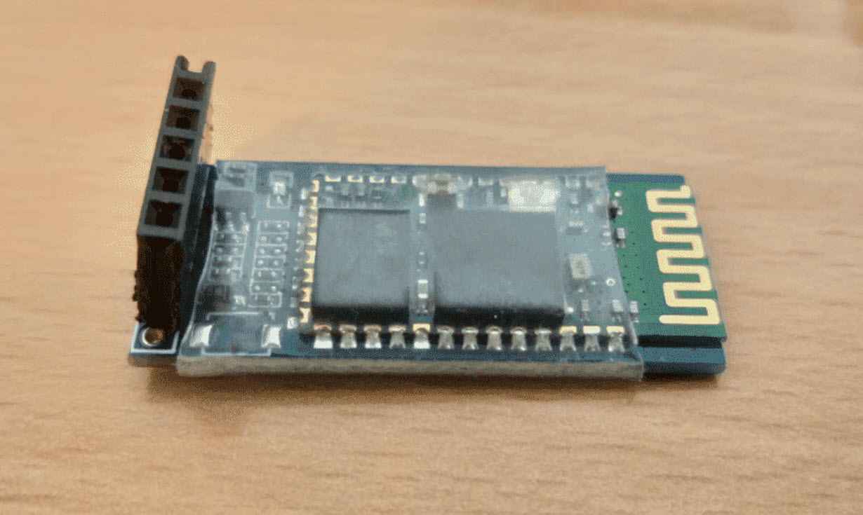
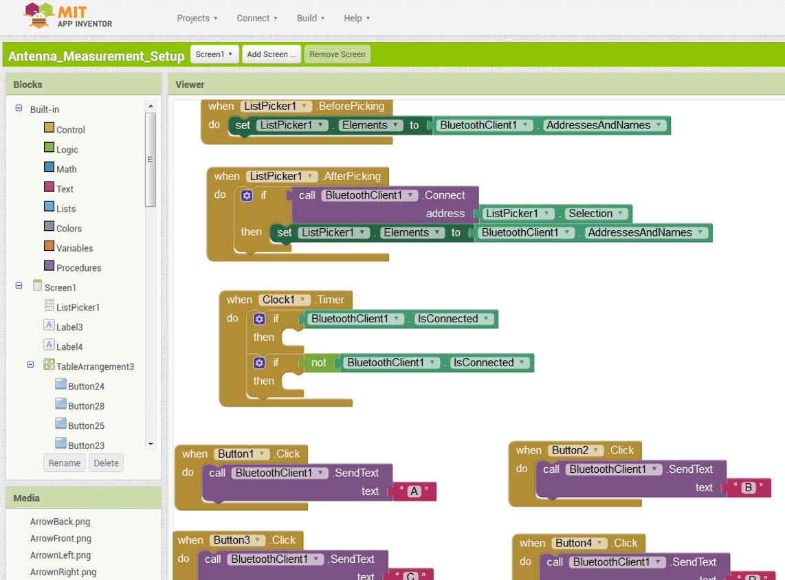
Networking and Application Programming
For Networking, I used the Bluetooth HC-06 Module which I also used in Week 14, For Application design I used MIT App Inventor. Plenty of Tutorails were available online that guided me to develop a nice application for controlling my Project. I followed this tutorial.

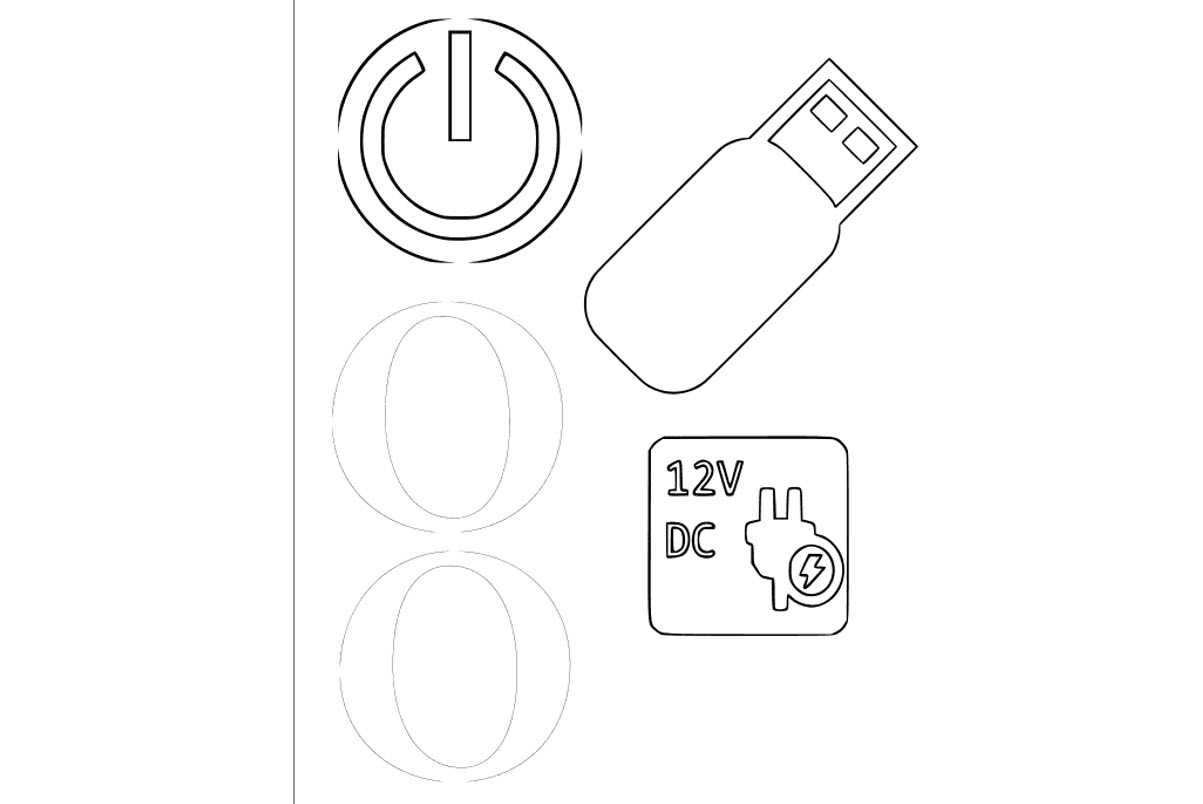
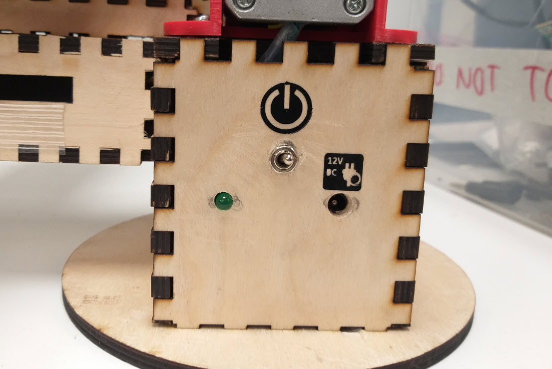
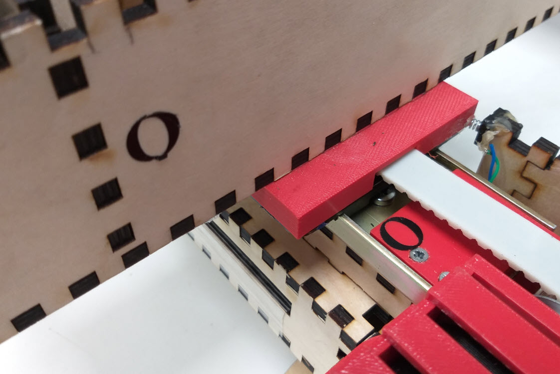
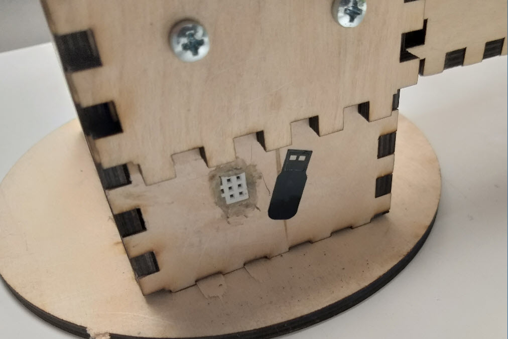
Vinyl Cutting
Finally, to get the Design some finishing touches, I Vinyl cutted some designs for the Indictors of ON/OFF Switch, Power Supply, Origin and Programming areas in the Final Product.
Final Prototype Model
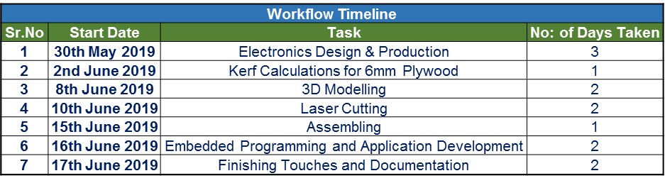
Workflow Timeline
Although I was able to get enough knowledge during my weekly tasks, still during my final project, I felt that I would probably need more number of I/O Pins thereby I had to mill the board again using ATMEGA 328P and it took the maximum time to get it working successfully. Also the Week 12 was very helpful which gave me enough knowledge to know how to control the stepper motors. I got used to Fusion 360 alot during the previous weeks and this assisted me to complete the final design quickly and efficiently with the required mechanical parts..
License

This work is licensed under a Creative Commons Attribution-NonCommercial-ShareAlike 4.0 International License.
Final Poster
Final Video
The Music for the video is royalty free and is taken from: https://www.ashamaluevmusic.com/corporate-inspiring
Files
- Main Board Schematic
- Main Board Layout
- Main Board Traces PNG
- Main Board Traces RML
- Main Board Outline PNG
- Main Board Outline RML
- Motor Control Board Schematic
- Motor Control Board Layout
- Motor Control Traces PNG
- Motor Control Traces RML
- Motor Control Board Outline PNG
- Motor Control Board Outline RMl
- Motor Control Board Outline holes PNG
- Motor Control Board Outline holes RML
- Laser Cut 01 SVG
- Laser Cut 01 PDF
- Laser Cut 02 SVG
- Laser Cut 02 PDF
- Laser Cut 03 SVG
- Laser Cut 03 PDF
- Final Code :: Arduino
- Vinyl Cutting Files
- Mobile Application File
- Final Project F3Z File
- Antenna Mount F3D File
- Final Project STL File
- Antenna Mount STL File
- LICENSE.txt