4.Computer controlled cutting
Assignment
Group assignment
-
characterize your laser cutter, making test part(s) that vary cutting settings and dimensions
As stated in https://vimeo.com/315759994 @ 58:14 “Look at the materials you going to be using. Determine what is the right speed, feed rate and pulse rate and experiment to make that too big or too small. what that means if you cut with too much or too little power. The second thing to do is to actually measure the kerf. Make a piece of known size. Check the size you actually got versus the size you put in.” -
Try to understand the ‘kerf’ of the laser
- What is kerf?
- Choose at least 2 materials and measure the kerf value for laser cutting of those materials.
Individual assignment:
- Cut something on the vinyl cutter design.
- Laser cut, and document a parametric press-fit construction kit, accounting for the laser cutter kerf, which can be assembled in multiple ways
Group assiment
Team: Gleb, Marjo, Lukasz and I.
One of the settings in laser cutting is the speeds and feeds of the cut. The laser cuts by firing energy on the focusing spot. By varying the power of the laser itself and the speed it moves across the cut material the amount of laser energy per length can be varied. More energy cuts deeper. But more time spend under the laser makes the melted kerf wider and may start a fire in combustible materials. by moving faster with higher power the heat buildup is smaller. The best cut and kerf is a combination of power and speed. From 3mm thick MDF board a couple of shapes were cut. The same job was cut by using a set of different settings.


Cut 1: 80/9 = 8.88 J/mm
Cut 2: 80/20 = 4 J/mm
Cut 3: 80/30 = 2.7 J/mm
Cut 4: 90/30 = 3 J/mm
Cut 5: 90/20 = 4.5 J/mm
None of the custom settings cut through the material. The energy calculations confirms the result. The custom settings results in lower power in the cut.
Kerf defenition
Kerf means the cut width and it’s tolerance. When cutting material from a piece of bulk material, the width of the cut’s lost material is called kerf. The removed material amount has to be calculated in the design of the cut of the part.
Kerf in lasercutting
Laser cutting kerf of the cut varies depending used laser power, speed,pulse frequency,ambient temperature and the material and it’s thickness. The laser power output is the power in wattage of the used laser itself. aka, the number of emitted photons per unit time. in CO2 Laser pulse energy can be adjusted by adjusting the driving energy of the CO2,N2,H2 and Xe gas mixture exciting electric pulse. Speed is the laser velocity across the cut material. Slower speed will inflict more energy and result deeper cut and vise versa. Frequency is the laser pulses in second. higher frequency makes more pulses per unit length that puts more energy to the cut material. In rastering the DPI measures the used resolution points per inch(25.4mm) more DPI will make finer details in pictures, but will also inflict more energy to the surface. Excess DPI may burn the material surface.
Calculable parameter is the absorbed volumetric energy. More absorbed energy during gutting causes wilder kerf.
Unlike traditional mechanical cutting, where the width of the blade is exactly the width of the cut, in laser cutting the radiated heat of the main laser is absorbed to the surrounding material. The material right next to the cut burns or melt little further apart than the actual width of the laser beam. This widening is more severe in dark materials and in materials that melt easily.
Burn resistance material and carbon/silicon sponge-forming materials resist the effect.
Also in laser cutting the leveling of the cutting plane is crucial for kerf. Minuscule variance in focusing distance will affect kerf drastically.

Top-down view of cutting.
The effect of heat to kerf in laser cut. 1.Laser beam. 2.Bulk material. 3. Laser beam width kerf. 4. Extra kerf due to heat effects.
In MDF and other wood-based materials forms a carbon foam layer against the laser. The carbon foam can withstand extremely high temperatures and makes the kerf narrower. CO2 lasers operate in the IR region. The IR radiation is more easily scattered from the evaporated material. Fiber and diode lasers are usually shorter wavelength and the scatter pattern is diminished.
Using CO2 laser the kerf is not usually unified width along the thickness of the material. As the laser stars to evaporate material during cut the laser is scattered when it hits the evaporated particles. As a result the top part of the cut will exposure to a sideways scattered laser and heat and will be affected more than the lower parts of the cut. This result can be also seen in thicker materials where the effect is more pronounced.
 Side sliced section view of the cutvisualise the non-uniform kerf in z - direnction.
Source. Me and my Samsung Galaxy S9 Kids Dwar Free Drawed one handedly while biking in -24’C.
In the video the evaporated and superheated particles can be seen forming a light beam coming from the cut. Some particles can be seen traveled upwards and making a light blinks as particles interact with the laser beam.
As a result the most tighter press fit connections must be designed to the laser cutter itself. Moving to another laser or adjusting the power of the laser will change the kerf.
Some web reference CO2 laser Kerfs.
| Material | Thickness | Average Kerf |
|---|---|---|
| Acrylic | 1mm-3mm | 0.18mm |
| Acrylic | 5mm-8mm | 0.21mm |
| Acrylic | 10mm-15mm | 0.3mm |
| Acrylic | 20mm | 0.32mm |
| HIPS, PETG, Styrene | 1mm-3mm | 0.45mm |
| Birch plywood | 0.8mm | 0.08mm |
| Birch plywood | 1.5mm | 0.16mm |
| Birch plywood | 3mm | 0.2mm |
| Birch plywood | 6mm | 0.22mm |
| Birch plywood | 12mm | 0.3mm |
| MDF | 3mm | 0.16mm |
| MDF | 6mm | 0.2mm |
| MDF | 12mm | 0.28mm |
| Veneered MDF | 6mm | 0.17mm |
| Greyboard | 1200microns | 0.08mm |
| Greyboard | 2400microns | 0.12mm |
| Paper | 90 – 350 gsm | 0.08mm |
Kerf Measurement
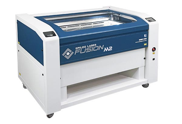
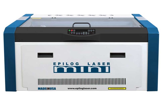
Kerf measurements was done on Epilog Fusion M2 40 (75W) on bulk MDF. and Epilog Mini 24 (60W) on opal 70% translucid optic diffusive PMMA.


During cutting a nominal safety and security methods were followed:
The safety instructions from Epilog states:
NEVER let the laser system operate if it will be unattended.
KEEP the area around the machine clean and free of clutter, combustible
materials, explosives, or volatile solvents such as acetone, alcohol, or
gasoline.
ALWAYS keep a properly maintained and inspected fire extinguisher on
hand. Epilog recommends a Halotron fire extinguisher or a multi-purpose
dry chemical fire extinguisher. The Halotron extinguishers are more
expensive than a dry chemical, but offer certain advantages should you
ever need to use an extinguisher. The Halotron extinguisher discharges a
clean, easily removable substance that is not harmful to the mechanics or
wiring of the laser system. The dry chemical extinguisher discharges a
sticky, corrosive powder that is very difficult to clean up.
ALWAYS use air assist when vector cutting.
BE CAREFUL! when vector cutting. Many materials have the potential
to burst suddenly into flames – even materials that may be very familiar to
the user. Always monitor the machine when it is operating.
KEEP YOUR LASER SYSTEM CLEAN – A build up of cutting and
engraving reside and debris is dangerous and can create a fire hazard in its
own right. Keep your laser system clean and free of debris. Regularly
remove the vector grid to clean any small pieces that have fallen through
the grid.
The cutters were attached to flue gas outlet filter, the cut material were checked for elements that are problematic for laser cutting. Mainly halogens and heavy metal traces. both Polymethyl methacrylate and the High density particle board did not had these elements in them. The cutting progress was monitored during the whole cut time for fire safety. In the lab there are several fire extinguishers.
Kerf was measured by making multiple cuts in a pattern of a latter and measuring the total length of the together pressed parts. The (result - original length)/ number of cuts is the average kerf for those cuts. this method was used because the limited tools to measure. Measure caliber error is high in under 10mm and over 150mm distances. The expected measure length of 90-100mm was in the smallest error area of the used caliber.
The test pattern was cut from MDF and from 3mm Opal 70% translucent PMMA

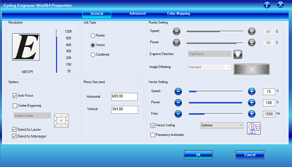
The test pattern was drawn in Inkscape. The Inkscape line vectors was defined to be 0.02mm in width. 0.02mm is the Epilog laser default parameter for to the laser to cut the vector. Any other line width will be only rasterized. The now right dimension having .svg file was exported to ISO 32000-2:2017 PDF standard format file. The . PDF file was opened in Acrobat reader. The Epilog laser cutter is specified as printer. The document was printed by pushing the print button. in the print settings page the Epilog settings can be accessed by selecting the Epilog Engraver as the printer and by pushing the Advanced options button.
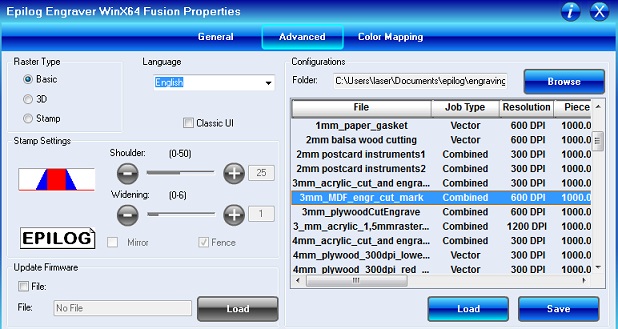
The used settings was as follows:

The settings for the materials to be cut were already saved to the Advanced settings materials page. The correct material was selected and the Load button pressed.

After the setting are loaded and after check that the autofocus is selected the OK button can be pushed. Before the print button can be pushed, the material needs to be inserted to the cutting plate and the origo of the cut need to be selected. The origo of the cut is in the left upper corner of the picture. The cutting head is moved to an area where the whole cut is in the area of the cut material and a Home Zero option button is given. This button is the Jog joystick itself in the Epilog Fusion M2 40 (75W).

In the other smaller machine,the Epilog Mini 24 (60W) there is a dedicated button for Home zeroing. Sometimes weights needs to be placed in the material being cut to force it straight. If the material is bugled the focus and the kerf will vary tremendously. Even possible to not cut the material anymore, because the laser energy is spread too wide of an area.
After origo placement the print button can be pressed. The laser will not start to cut immediately but a go button needs to be pressed on the laser itself before the cut is begin.
The cut pieces were assembled tightly side by side and resulting length was measured.

(Ignore the odd measurement in the picture. The calibers battery was low and gave wrong results.) The measurement was shorter than original 100mm.
Measured MDF: 98.2 mm
Measured PMMA: 95.3 mm
The calculated kerf:
MDF: (100- 98.2 mm)/ 20 = 0.09 mm
PMMA: (100- 95.3 mm) / 20 = 0.235 mm
Measuring was at times challenging because the pieces jumped up when pressed together because of the wedge shape of the cut pieces.
In the laser cut test pieces show the non-uniform kerf in z- direction


In PMMA the pulsing of the laser can be seen after a high speed cut

Individual assignment: Parametric permutable laser cutN-gon pattern tower
Parameters
As a parametric design I designed a laser cut diffuser and/or design piece.
Idea is to make N-gon pattern tower that can be controlled by parameters.

Controll parameters:
1. Kerf.
2. Material thickness.
3. Height of the center tower.
4. Number of the center vanes.
5. Number of center vanes tabs.
6. Center vanes width.
7. Outer vanes height.
8. Number of outer vanes.
9. width of outer vanes.
10. Number of outer vanes tabs.
From these parameters Inventor updates and assembles n-sided tower, inner N-walled tower, base to hold the outer and the inner pieces. the tower can be assembled multi height way.
The parameters also calculates and gives out a Kerf tester pieces. that tested the outer and inner tabs and the platform insert tab kerfs.
Some additional(39pcs) derivated parameters needed to be calculated to achieve the desired geometry.

For example the taps kerf are calculated in a way to positive tab the tab is half of a kerf slimmer on both sides and the negative side is a half of a kerf wider on both sides. So the to the positive tab side is removed the kerf amount and to the negative side one kerf amount is added. By this the tabs are precisely right size for tight press fit.
The additional parameters calculates the parametric outer and center tab height and the necessary kerf for every tab type.. Parameters also dictate the platform insert tab and the insert hole dimensions. Parameters also calculates also the needed tab depth increase depending of the varying angle of the vanes in shallow angles in high number vane configuration.
The number and the width of the canter and outer vanes calculates also the diameter and the positioning of the insert holes in the platform.
Some parameters and their calculations:
Teethheghtnegativetab= ( Height / ( Nofteeth * 2 ul ) ) + Kerf
Teethheghtpositivevetab= ( Height / ( Nofteeth * 2 ul ) ) . Kerf
Some additional simple math has to be done for the tabs depth. At 90 degree angle the tab length would be same as the material thickness. as the angle decreases some additional length has to be added to get same frictional grip as the 90-degree tab.
The extra length coming from the geometry of the cutsheet. In the sides are in 90 degree angel and from the center of the material the extra length is calculated by = Cos(360/Numvertex) the maximum extra length is when the wanes are in 45 degree angle of each other to gave to space to the corner of the material
tapdepth = materialThickness + Kerf + angleconverter
The number of the vanes and the width of the vanes gives the final size of the circumference of the lampp. This is calculated by :
circumferenceOuy= ( materialThickness * 2 ul ) + ( width / ( 2 ul * sin(PI / Numvertex) ) ) * 2 ul
The tabs that go downward to keep the vanes in place have to be precise at right place. This is calculated by:
Platformtabs= ( ( width / ( 2 ul * tan(PI / Numvertex) ) ) - 6 mm ) * 2 ul
These calculations are doubled for the center pillar that holds the LEDs.
 Parametric tab design uses the Rectangular Pattern-Tool
 The platform insert pattern uses the Circular pattern tool.
 The automatic Kerf tester dimensions.
 Precut kerf tests. The testing of kerf takes multiple test sometimes.
 The automatically generated Sketch is imported to Drawing view. and exported to PDF.

The exported PDF is then imported to Inkscape. Where cutting pattern and placing is done. After the pieces were cut using the settings used in the kerf measuring group assignment.
 The Kerf if so absolutely perfect that the outer wall vanes can be held together against gravity only by the friction of the tabs against each other.

First assembled center tower test.
 First assembled outer tower test.

 First test of assembled permutation with lights.
One of the different ways to assemble the press-fit construction kit. The number of different ways to assemble the kit can be calculated by: (Nc-3)nc + (No - 3)no ,where Nc = Number of center vanes, nc = Number of center vane tabs, No = Number of outer vanes, no = Number of tabs of outer vanes. “-3” is used because the wall needs at least 3 anchor points to stay stable so 3 vanes must be orientated at lowest level as a feets.
In example lamp (6-3)6+(12-3)6 = 18 + 54 = 72 permutations.
Some test animations.
Individual assignment: The vinyl cut silhouette image for the N-gon pattern tower light.
The used vinyl cutter was the Roland GS-24 Vinyl cutter.

The vinyl image to be cut is a landscape figure to the N-gon parametric press fit assemble kit lamp.
The image to be cut was made in Inkscape.
First a grass silhouette were made.
 the second part is a svg tree from Free Clip Art Libary
 The grass was copied to the image and multiplied enough times to get the inner circumference of the press fit kit.
 Because of the extra lines between the multiplied grass and the tree the picture cannot be used as is. only the outline is useful cut line. Removing every line by hand is not an option because there are large number of them. This is bypassed by making the vectors to completely black and exporting the image to png, importing the png back to Inkscape and tracing the bitmap outline.


 The traced outline vector is used for the cutting.
 From the materials rack the white vinyl was selected. It causes a good shadow and is invisible when the LEDs are off.
The roll was placed to the machine, the rollers were set to the right places. the machine measures the width of the material from the placing of the guide rollers.
As the vinyl was placed into the cutter the roll option was selected for the vinyl.

 The svg vector outline was opened and the print button was pressed. on the settings the Roland GS-24 was selected.

From the settings panels the Cutting area was set by pressing the Get from machine. Because of the length of the image the Rotate was put to 90deg to fit the image to the roll. The start point of the print is the left bottom corner of the image. the image fits in rotated orientation to the 373x500mm area.
After this the print was started by pressing print.
The cut image was then transferred via help of a long ruler to the vanes of the press fit kit.

 The grass came off surprisingly easily.
 Transplanted vinyl.

Test for the silhouette.
 Final vinyl silhouette on the press fit kit lamp-
The files in this weeks work can be found in the gitlab repo
Reflection.
I am somewhat experienced in laser and in vinyl cutting. This week I wanted to make one option enclosure for my final project. this was a good exercise in geometry calculations for the pressfit kit. Someday I would like to try laser cut PCB:s. either direct method or paint laser removal and etching method.