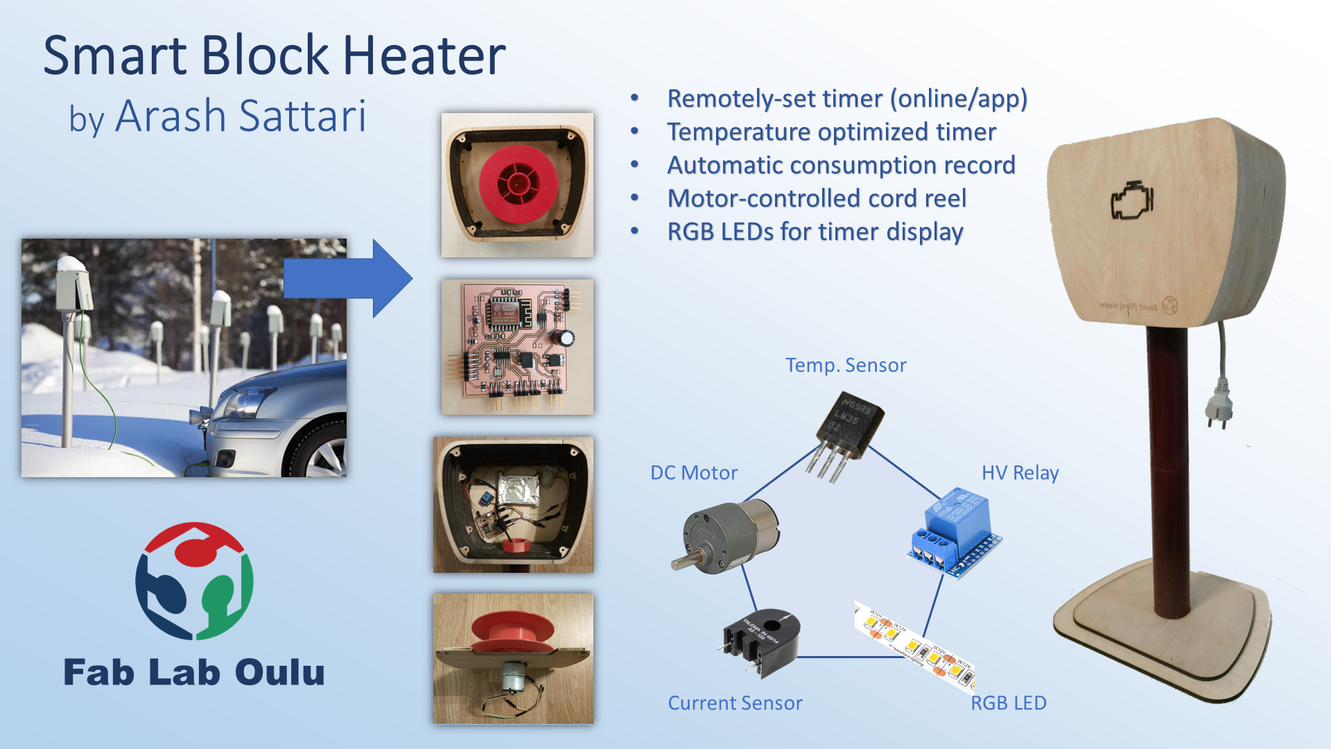
Smart Parking Block Heater
This page shows an overview of the design idea, concept justification,
implemented design result and suggestions for its further improvements.
For a detailed diary of the development process, overview of
the required set of skills, please refer to
Project Development Week's documentation.
Idea and Motivation
This idea has been in my head for a few years now! It is common
knowledge that Finland is a cold and dark country (especially here
in the northern parts)! Finnish winters are too much to bear,
even for the cars! Car engines cannot work properly in subzero
temperature (especially below -15 degrees). The main issue is during
the first few minutes after starting the car, since the engine oil
has lost its low viscosity, the fuel does not burn well,
the emission of pollutants increases and the engine becomes damaged
gradually. To prevent all that, most car engines have an
extra electric heater mounted near the engine, which warms it up
externally for a few tens of minutes to a few hours
(depending on the temperature of the parking area) before starting
the car. Therefore, we have here
in every car parking, an electrified pole with a timer and a socket.
Conventional Car-heating is timer-controlled.
There is a timer for each plug socket, and the user can set it
as needed for two hours. When you want to set the heating time,
you need to turn the outer ring of the timer clockwise until the
red arrow points at the time that you want your car to be ready for
use. For example, if you want your car engine to be warm at 3 pm
(i.e. at 15.00 on the 24-hour clock), turn the outer ring so that
the red arrow points at number 15. The heating will start at 1 pm
(i.e. at 13.00 on the 24-hour clock) then. The green arrow on
the ring shows the time when the heating starts. The white
triangle outside the ring of the timer must point at the current time.
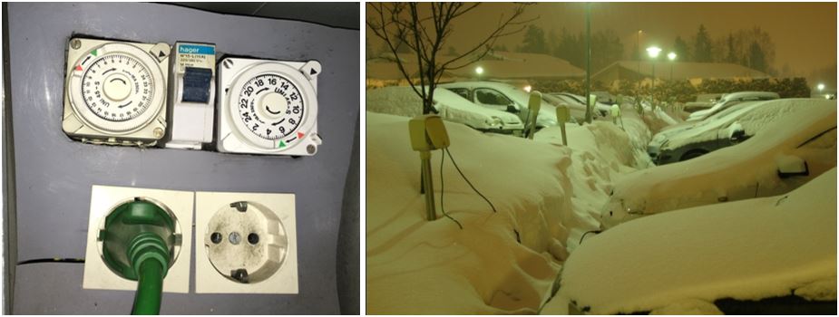 Figure 1.
 Conventional block heater.
Some of the disadvantages of this system are:
1. Users does not always know when they are going to use the car next time.
2. The system keeps the heater turned on for two hours regardless of ambient temperature (it does not matter if the weather is - 5 or - 25 degrees).
3. The block heater door has a lock that usually is frozen in the winter, and the user has to struggle every time he/she wants to change the timer values.
4. Parking fee for the block heater is fixed (regardless of the amount of electricity that user has consumed).
5. Usually users keep the cables always plugged
in the socket, because the subzero temperature stays for at least
a few months. Therefore, when the car is not in the parking,
the other end of the cable had to be protected by a lid, and
the user should make sure that it is not exposed to rain or snow,
while unplugged from the car. In the open parking areas,
this usually means carful wrapping of the cord around the block in a way
that the unplugged end faces downwards, and does not touch the snow!
My Design & Its Features
Inspired to find a solution for these issues, in my final project, I decided to design a smart block heater.
The design has the following features:
1. The user can set the timer remotely over the internet using an app.
2. The system has a temperature sensor to measure
the ambient temperature.
The app can estimate how long the heater has to be turned on
to prepare the engine to start for the desirable time.
3. The obtained temperature data can be used to set the heater timer more efficiently.
4. A solid-state relay will be used in order to turn the heater on and off by microcontroller command signals.
5. The block heater pole will have a motorized cord reel controlled by the user through the UI,
therefore the users do not need to carry his/her own cord or worry
about it plugging it in and out or wrapping it every time.
There is no need to open block heater’s door to adjust the timer.
Therefore, there is no need to lock and unlock it.
6. RGB display LEDs for tracking timer’s on/off states and the remaining time.
I started with this preliminary sketch of the system shown in the images below.
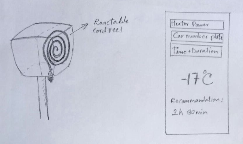 Figure 2.
 Design Sketch.
I did all the design and implementation of the smart block heater on my own,
and I did not use any code or design from previous students of Fab Academy.
However, I used a few Arduino libraries for my sensors and outputs,
which I referenced in the explanation of the development process.
Here is a summary of the project's features and parts:
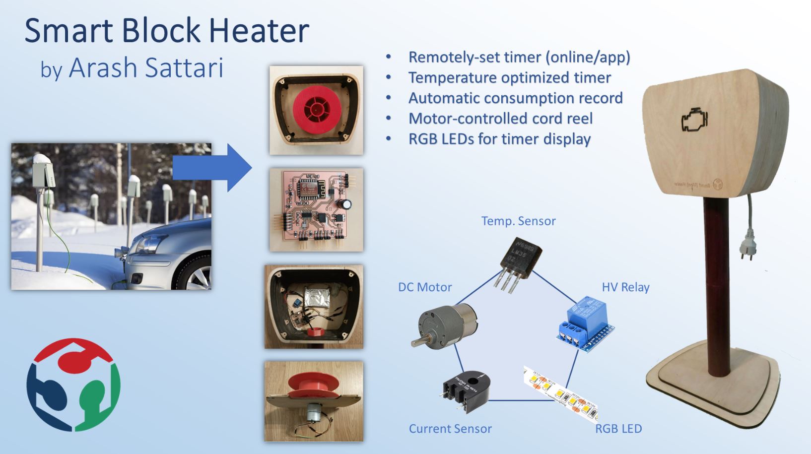 Figure 3.
 Design Summary.
Materials & Components
The material and components that I used mostly came
from Fablab Oulu inventory. In the following table,
a list of the material and their prices is given. The estimated
price of this prototype is 57 euro.
More detail about
the component and material features in the Project Development page!
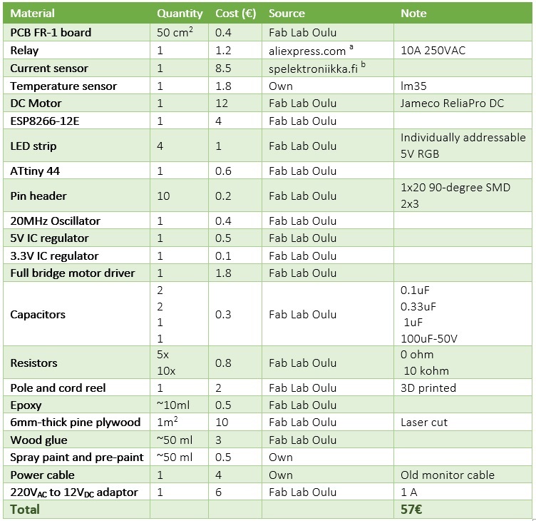 Figure 4.
 Materials and components, their source and cost
(
a and
b).
Parts & Systems
Fig. 5 shows the different systems and the parts that were designed and assembled for building the project,
and the processes that were required by each:
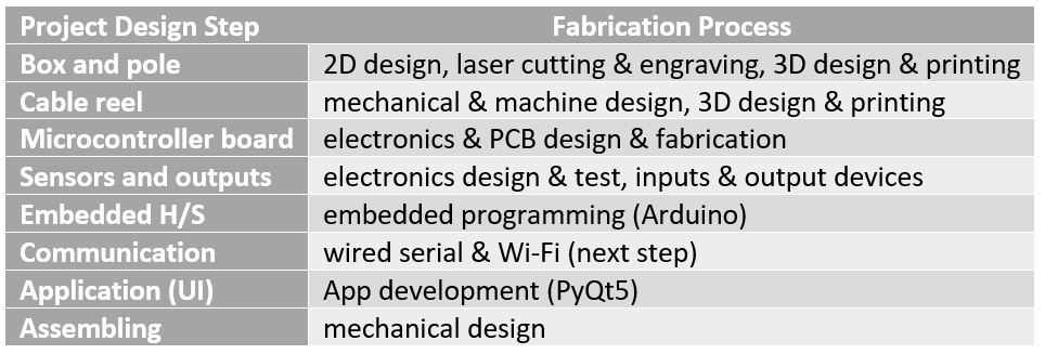 Figure 5.
 List of project's parts and involved processes.
All the parts and systems are explained in detail in the 'Project Development' week.
I give a short summary of the designed and implemented parts here (Fig. 6):
- The box was made of 6mm-thick pine plywood with curved sides.
stacked the side/top/bottom parts that I had laser cut and glued them together.
The front of the box has a transparent LED display and engraving.
- The pole is 3D printed (two part pressfit and thread/bolt connection to box) and the stand is laser cut wood.
- The cord reel is 3D printed and attached to a DC motor.
- The electronics is a microcontroller (ATTiny44) board, with all parts integrated on the same PCB.
- An LM35 temperature sensor, and three outputs (relay, LED strip and a DC motor)
are implemented and all controlled by the embedded code implemented on ATTiny44.
The temperature sensor is used by the embedded code to optimize the timer.
The relay connects/disconnects the system from power. The LEDs show the state of the system and the remaining time.
The DC motor is used for automatic roll up/down of the cable.
- The Arduino code orchestrates all the functions.
- The serial data connection provides communication between the system and UI.
- The desktop user interface lets the user interact with the system, change its settings,
activate/deactivate it ...
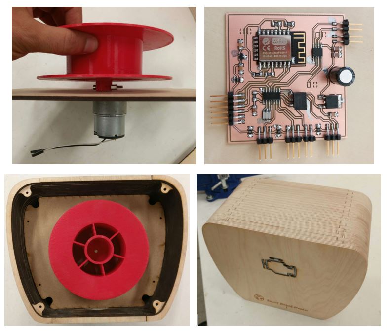 Figure 6.
 Summary of parts and systems.
Evaluation & Final Result
Each part of the system was tested separately during the
development process (all the test codes, configurations and results can be found in the Development week's report).
For testing the final assembled project, a routine of block heater use was completely tested and
the test video is presented here. (user rolls down the cord and sets the ready time using the UI, the block heater
calculates on/off times based on temperature, connects the relay when needed,
updates LEDs to show remaining time, disconnects the really when timer runs out and updates LEDs to show
that heating is completed, rolls up the cord at user's request). Fig. 5 shows the final assembled system.
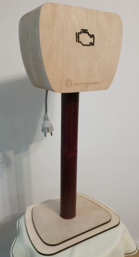 Figure 5.
 Final project's result.
The final presentation slide and video can be found
here and here, respectively.
The presentation video shows, along with other things, short videos of two of the above-mentioned test routines.
In the first one:
- The user sets a ready time in the UI.
- The UI calculates the start and end time of heating based on the temperature.
- It starts the timer at the calculated start time
(the LED blinks three time with blue color, representing cold engine),
and connects the relay at the same time.
- The timer counts down to the end time, and during this process,
the LED gradually changes color from blue to red (warm engine).
- When the timer stops, the relay disconnects, and user gets a message in
the UI that the engine is warm and ready. The LED turns off.
The second test video shows the motorized roll down of the cord at user's request from the UI.
Questions & Future Work
• I used a serial wired connection for this prototype.
As mentioned, I have also implemented a WiFi option on the board. This
capability can be combine by an android version of the app to
make a remotely controlled version.
• The system can have the option to measure the electricity consumption using a current sensor
and store it in a database. In this way, parking rent can be
based on the amount of electricity that the user has consumed.
• The UI provide the user with entering the power of the heater
and the model of the car somewhere in the app (just once) to further optimize the timer.
• Is there anyway to reduce the costsSpecifically in creating the pole and box with cheaper material?
• How should this design be change, so that it can work reliably in subzero temperatures outside?
• Doesn't a GPRS module (SIM900) embedded with an AVR microcontroller provides the data transfer capability?
• I probably need a more capable microcontroller, if I want to add more
features or be more efficient. What exact specifications does it need to have?
License
I decided to choose the MIT License for my assignment work
but leave the final project under default copyright for now.
Since I would like to research the possibility of further developing
this into a commercial product, I decided not to license it yet.
I will try to gather more information
about this after the project deadline and make a decision then.