Assignment
GROUP PROJECT:
Use the test equipment in your lab to observe the operation
of a microcontroller circuit board
Redraw the echo hello-world board,
add (at least) a button and LED (with current-limiting resistor)
check the design rules, make it, and test it
extra credit: simulate its operation
What I did
- Started learning Eagle.
- Setting design rules for PCB.
- Milled PCB and soldered components.
- Programmed board using arduino.
Step1: Getting introduced to some concepts
- What is library in electronics design?: Every component has it's own library that tells what is the symbol of this component and what is his actual dimensions.
- What is schematic in electronics design?: A representation on electrical circuit elements with symbols and how these elements are connected to each other.
- What is layout in electronics design?: A representation of the how electronics component will be laid out in the board.
I read the introduction to eagle tutorial and it shows more about schematic symbols and layout.
Sample Schematic
To help you along, you can build off the Hello Echo example. Start by adding the necessary components to these example files: hello.fdti.44 schematic
- Go to documents and copy the extracted folder into your Eagle folder.
- Mac: In your "Documents" folder > eagle
- Ubuntu: In your "home directory" > eagle
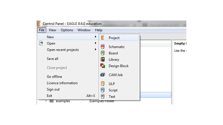
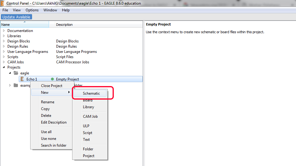
Windows: In your "Documents" folder > eagle Open Eagle Open the helloEcho schematic you downloaded
What is a Schematic?
A schematic in electronics is a drawing representing a circuit. It uses symbols to represent real-world electronic components. The most basic symbol is a simple conductor (traces), shown simply as a line. If wires connect in a diagram, they are shown with a dot at the intersection. This is what the schematic for "echo.ftdi.44" looks like
Autodesk Eagle
EAGLE (Easily Applicable Graphical Layout Editor) is a flexible and expandable EDA schematic capture, PCB layout, autorouter and CAM program. EAGLE is popular among hobbyists because of its freeware license and rich availability of component libraries on the web
There are installers for Mac, Linux and Windows. Choose the appropriate one for your operating environment and install it. Autodesk offers a 'Personal Learning License' for individuals working on non commercial projects.
EAGLE (Easily Applicable Graphical Layout Editor) is a flexible and expandable EDA schematic capture, PCB layout, autorouter and CAM program. EAGLE is popular among hobbyists because of its freeware license and rich availability of component libraries on the web. I have littile bit experinece with eagle so i choosed eagle to design the board , i also have the student licence .
Components needed
First of all I need to add the library of the componets , in here we have a git repo that include almost all the library that used in fablab.
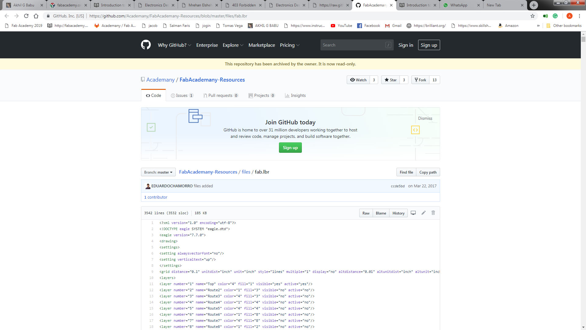
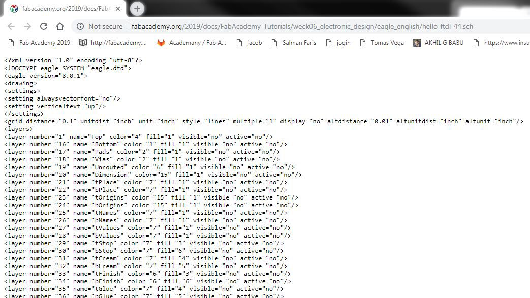
There is no download option for single file github , so i choosed View Raw to get all the code.
This is acutally a XML file that describe the dimmension of the componets.then i copy all the code and created a file named fab.lbr and pasted there.
Here you can downlaod the Fab Library fab.lbr
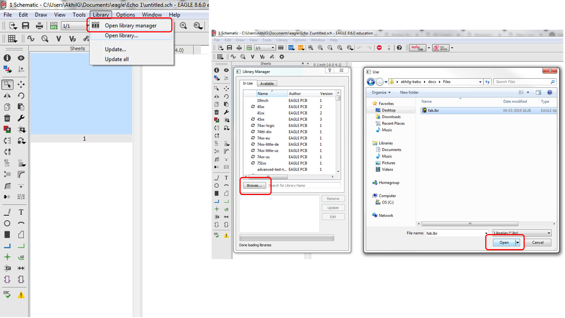
On the following window click Browse then select our Library file from it's location and click open.
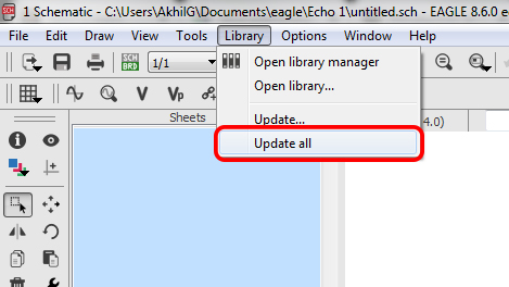
Next we needed to update the library by clicking the Update all option. We need to check that the library is updated or not , but seaching the componets list.
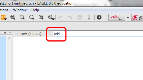
Type add on the command Section to add componets to our Schematics.
If we updated the library we can see like this , this means we are updated the library. Now eagle setup is complete , we can now add componets to schematic.
Schematics
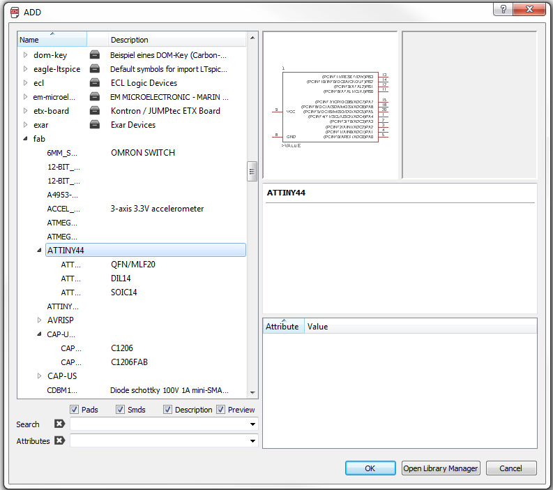
First I added ATtiny44,
Important :- you need to selecet the right componet that you have in your inventory
beacsue each of them look similar in schematic but when comes to pad length and distance and footprints it's huge difference.
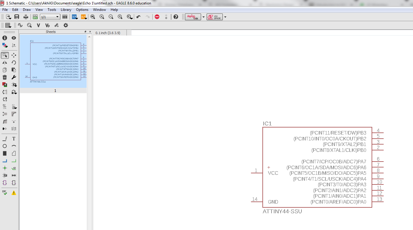
Place it anywhere on the schematic.
Add other components
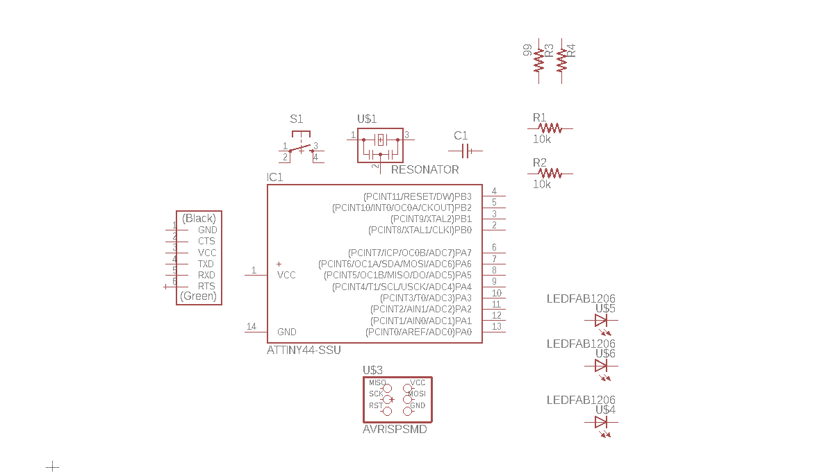
Next we need to connect the componet each other.
I used label tool label my componets so I can easly connect them together.
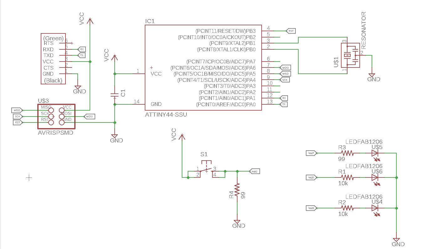
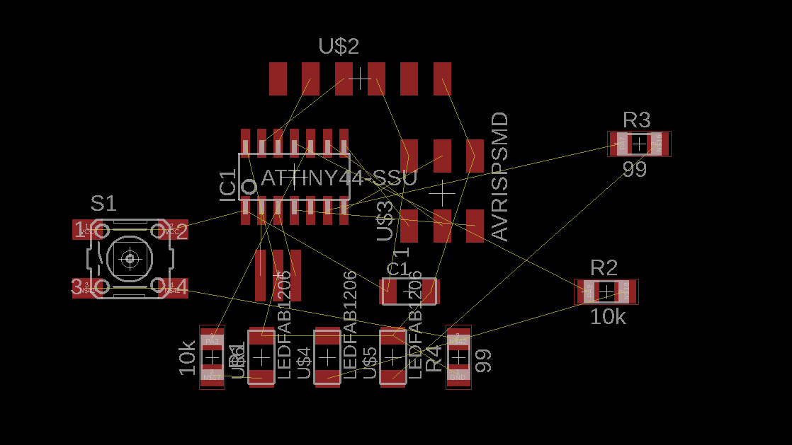
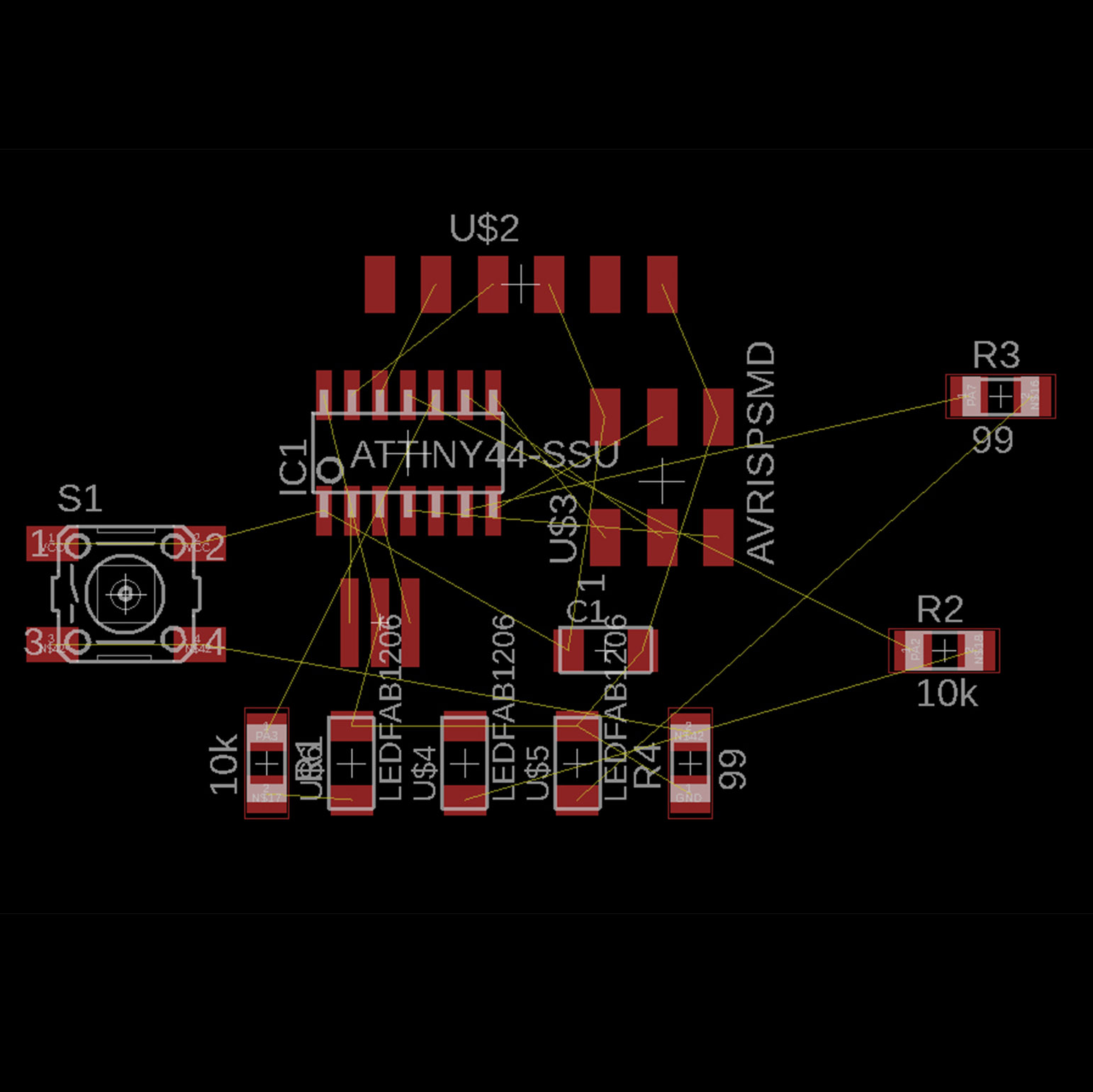
This is the schematics after completion.
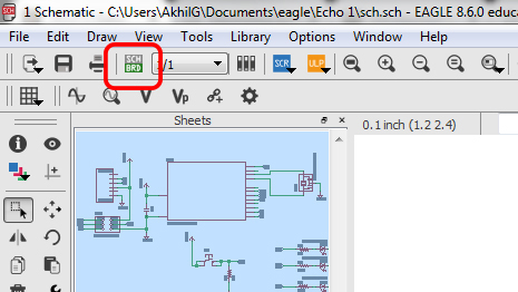
Once it is finished, select this button.
Next is the difficult task. The routing process is very time consuming.
Design rules
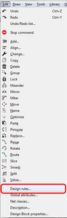
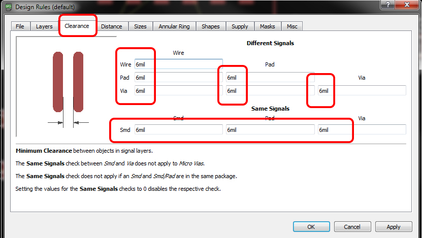
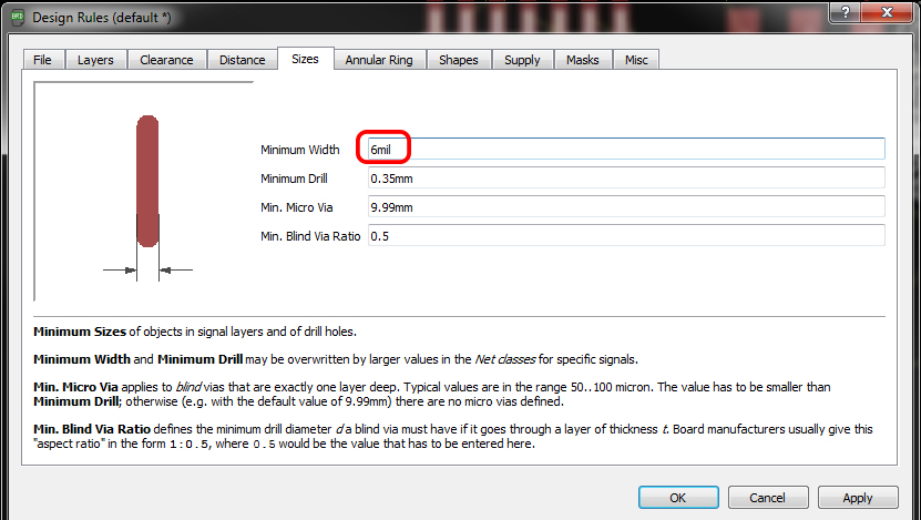
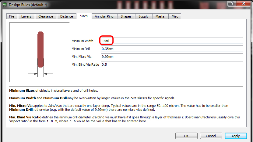
First we need to set the clearnce , by default it comes with the 6 mil, in fab we are using 1/64 bit for milling so here the trace will come around 16 mill.
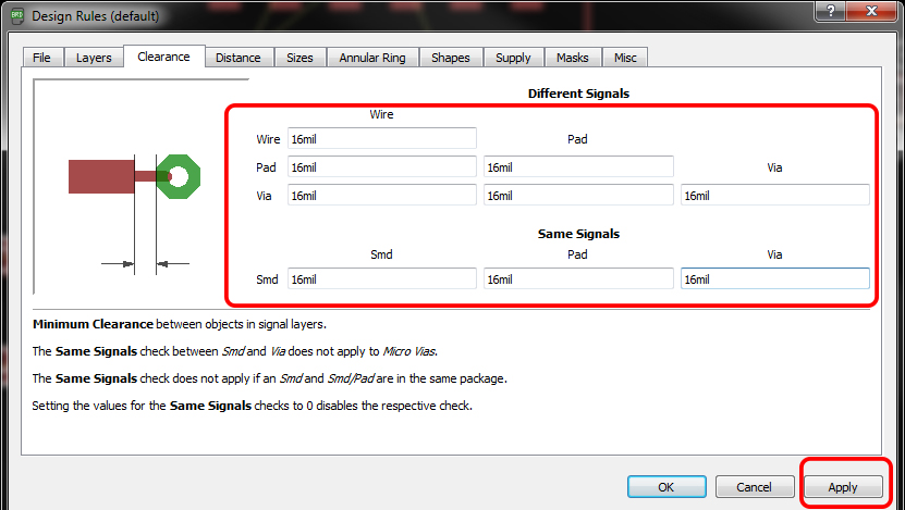
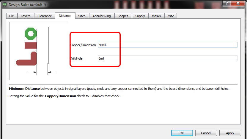
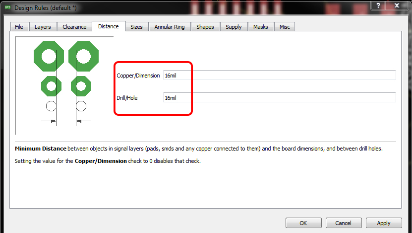
Next we need to take care the Distance, the default value is 40 mil so in here I have set the value to corresponding to our bit that is 16 mil.
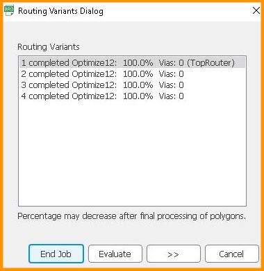
For routing, I used auto routing. In default it's comes with Bottom and Top layer , but here we are using One layer so used Top layer only.
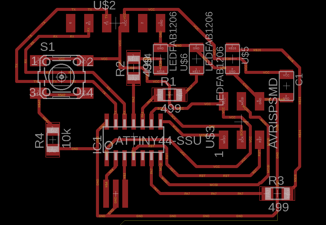
This is after auto routing.
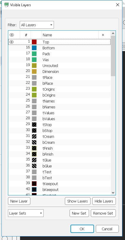
Now export mill trace and cur trace in ong format. To save them, hide unwanted lyers and save.
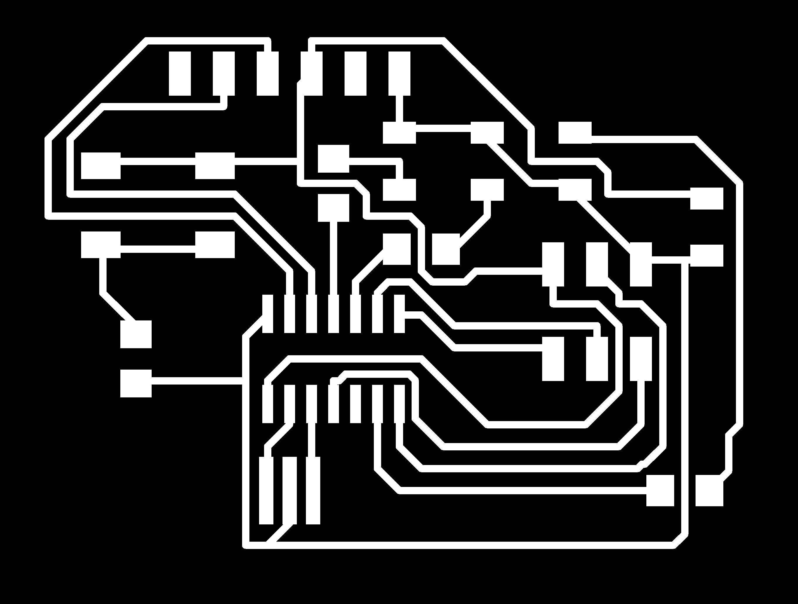
This is the mill trace.
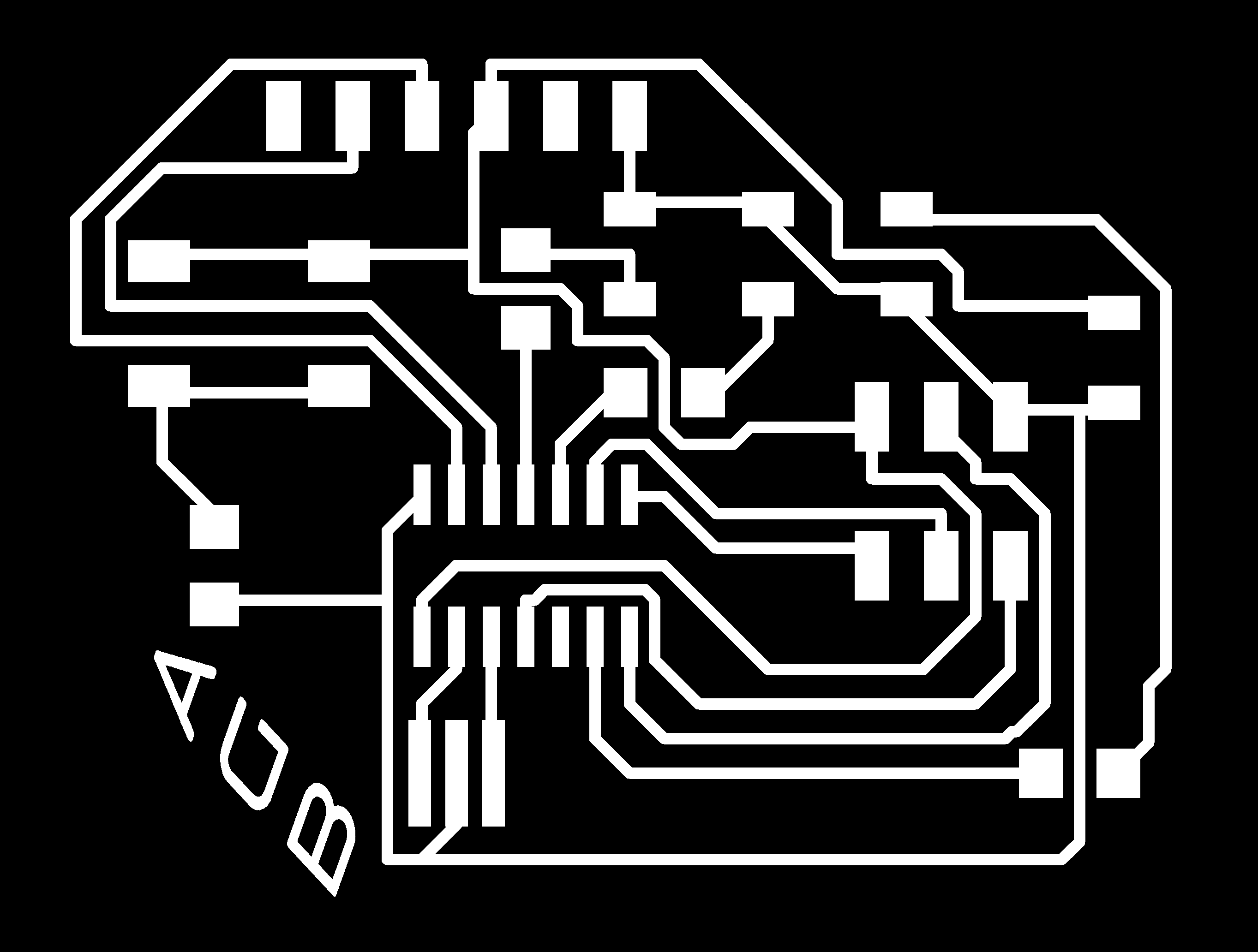
After making the png file i wanted to add my initials on the PCB. I used Adobe illustartor to add this.

Cut path.
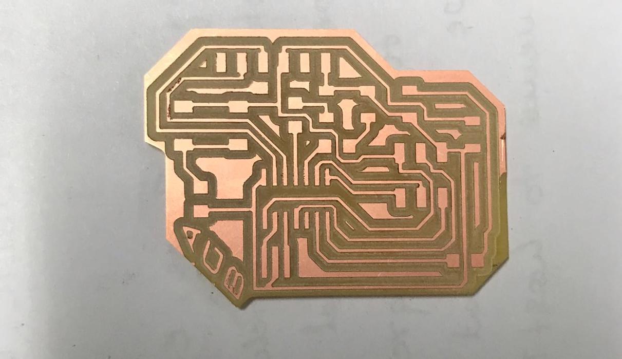
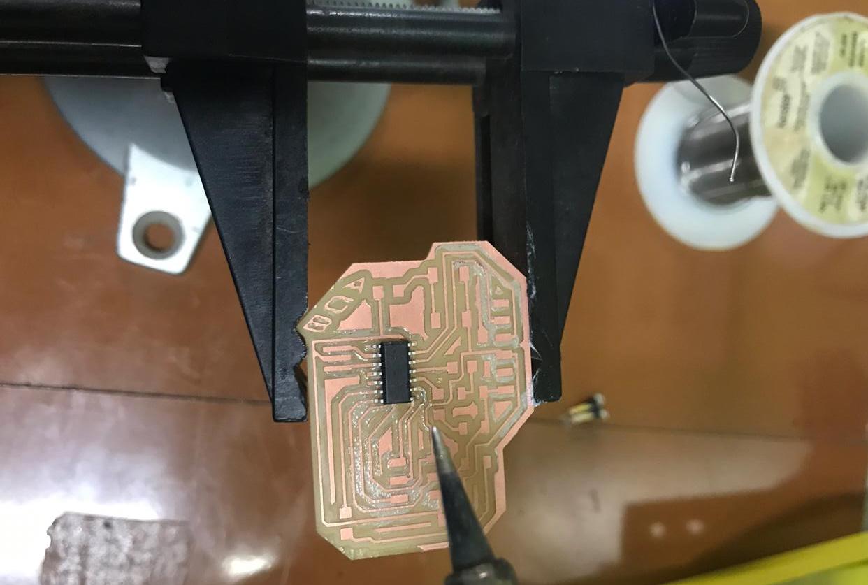
This is the circuit board after milling.
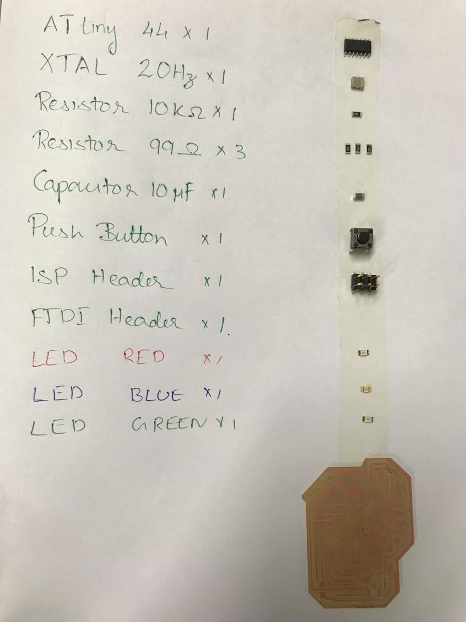
To organise the components I used two sided tape.
Soldering the components.
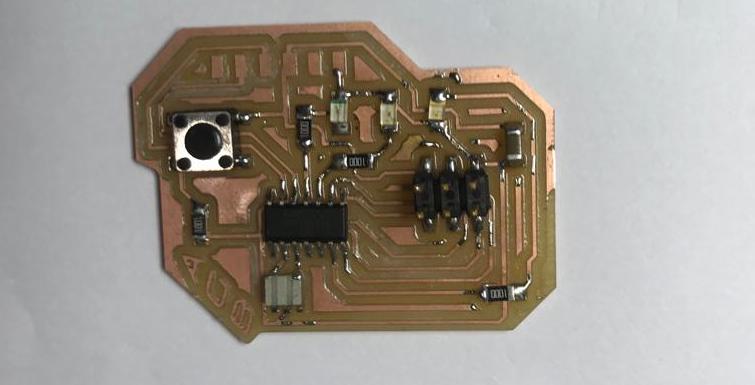
Hero shot.
Download the design files (.sch, .brd & .png files) here
Arduino code
For programming my board, I followed my instructer Suhail's fabacademy Electronics design page
                                                                        int red = A2;
                                                                        int blue = A3;
                                                                        int green= A6;
                                                                        void setup()
                                                                        {

                                                                               pinMode(red, OUTPUT);
                                                                               pinMode(green, OUTPUT);
                                                                               pinMode(blue, OUTPUT);


                                                                            }

                                                                            void loop()
                                                                            {


                                                                                digitalWrite(red,LOW);
                                                                                delay(75);
                                                                                digitalWrite(green,LOW);
                                                                                delay(75);
                                                                                digitalWrite(blue,LOW);
                                                                                delay(75);

                                                                                digitalWrite(red,HIGH);
                                                                                delay(75);
                                                                                digitalWrite(green,HIGH);
                                                                                delay(75);
                                                                                digitalWrite(blue,HIGH);
                                                                                delay(75);

                                                                                digitalWrite(red,LOW);
                                                                                delay(75);
                                                                                digitalWrite(green,LOW);
                                                                                delay(75);
                                                                                digitalWrite(blue,LOW);
                                                                                delay(75);

                                                                                }
Group assignment
This week's assignment was to use the test equipment in your lab to observe the operation. So let's meet with the electronics equipments
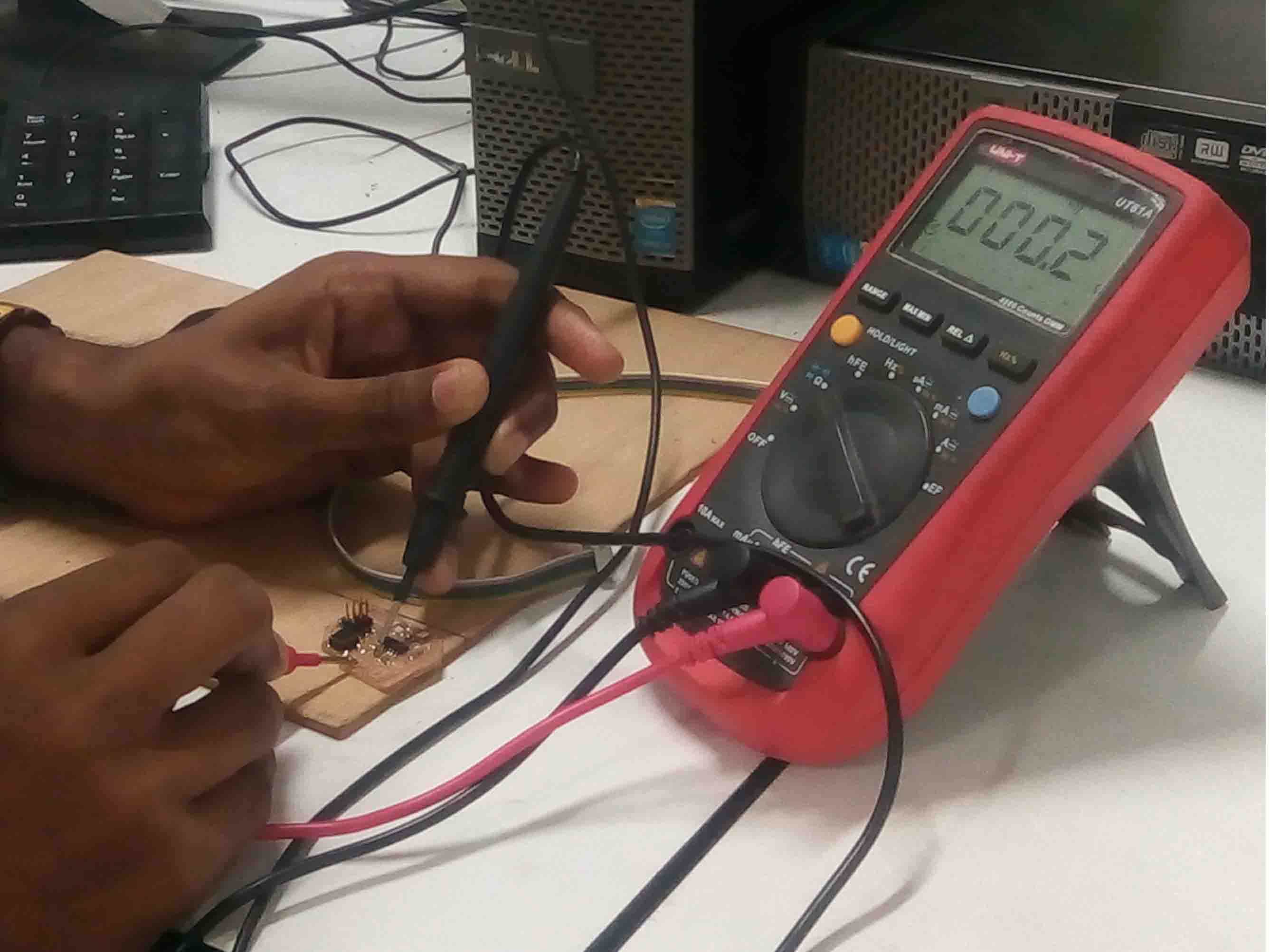
Multimeter
A multimeter is a tool for testing different parameters of an electronic circuit board.In our lab, we use UNI-T UT61A multimeter.
- Voltage
- Current
- continuity
- Resistance
- Frequency
- Capacitance

I used multimeter for testing continuity in my PCB
Digital Oscilloscope
In falab kochi we use UNI DSO-1100.
Features
- 100 MHz bandwidth, 1 M Memory
- High resolution color LCD display
- USB storage, RS232C & J45 interface
- 4000 point record length for each channel
- Multi-waveforms math, FFT Function
- Built-in delay sweep function
- Automatic Multi-waveform Measurement
- Cursor & Track measurement
- Waveform Record & Recall, Trigger Mode for Edge, Video, Pulse Width, Slope & Alternate
- Display of date, clock and help information
Function Generator
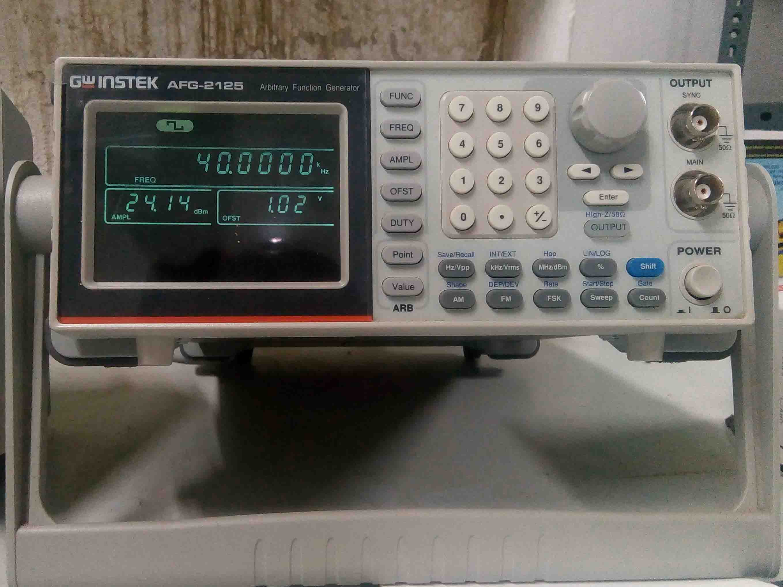
Features
- 0.1Hz to 25MHz with in 0.1Hz Resolution
- Sine, Square, Triangular, Noise and Arbitrary Waveform
- 20MSa/s Sampling Rate, 10 bit Vertical Resolution and 4k Point Memory for Arbitrary Waveform
- 1% ~ 99% adjustable duty cycle for Square Waveform
- Waveform Parameter Setting Through Numeric Keypad Entry & Knob Selection
- Amplitude, DC Offset and Other Key Setting Information Shown on the 3.5" LCD Screen Simultaneously
- AM/FM/FSK Modulation, Sweep, and Frequency Counter Functions (AFG-2100 only)
- USB Device Interface for Remote Control and Waveform Editing
- PC Arbitrary Waveform Editing Software
Download the design files from here