Assignment
INDIVIDUAL ASSIGNMENT:
Add an output device to a microcontroller board you've designed, and program it to do something
GROUP ASSIGNMENT:
Measure the power consumption of an output device
Output devices
Output devices allow computers to communicate with users and with other devices. This can include peripherals, which may be used for input/output (I/O) purposes, like network interface cards (NICs), modems, IR ports, RFID systems and wireless networking devices, as well as mechanical output devices, like solenoids, motors and other electromechanical devices. Some of the most common output devices that people are familiar with include monitors, which produce video output; speakers, which produce audio output; and printers, which produce text or graphical output.In this week assignment is to connect any output device to the circuit board
List of available sensors in my lab
- PIR
- Ultrasonic sensor
What I did
- Designed a PCB as a developer board
- Put all the pins out for adding componentsse
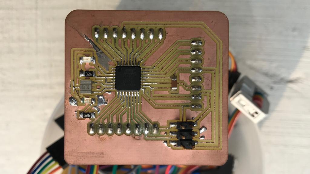
- Milled using Roland Modela Mdx-20
- Soldered components
- Programed The board using ISP
Servo motor
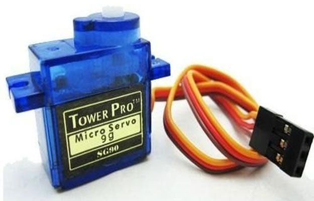
A servo motor is an electrical device which can push or rotate an object with great precision. If you want to rotate and object at some specific angles or distance, then you use servo motor. It is just made up of simple motor which run through servo mechanism. If motor is used is DC powered then it is called DC servo motor, and if it is AC powered motor then it is called AC servo motor. We can get a very high torque servo motor in a small and light weight packages. Due to these features they are being used in many applications like toy car, RC helicopters and planes, Robotics, Machine etc.
Servo mechanism
It consists of three parts:
- Controlled device
- Output sensor
- Feedback system
It is a closed loop system where it uses positive feedback system to control motion and final position of the shaft. Here the device is controlled by a feedback signal generated by comparing output signal and reference input signal. Here reference input signal is compared to reference output signal and the third signal is produces by feedback system. And this third signal acts as input signal to control device. This signal is present as long as feedback signal is generated or there is difference between reference input signal and reference output signal. So the main task of servomechanism is to maintain output of a system at desired value at presence of noises.
Source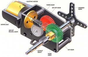 Source
- The servo motor is used in robotics to activate movements, giving the arm to its precise angle.
- The Servo motor is used to start, move and stop conveyor belts carrying the product along with many stages. For instance, product labeling, bottling and packaging
- The servo motor is built into the camera to correct a lens of the camera to improve out of focus images.
- The servo motor is used in robotic vehicle to control the robot wheels, producing plenty torque to move, start and stop the vehicle and control its speed.
- The servo motor is used in solar tracking system to correct the angle of the panel so that each solar panel stays to face the sun
The Servo motor is used in metal forming and cutting machines to provide specific motion control for milling machines - The Servo motor is used in Textiles to control spinning and weaving machines, knitting machines and looms
- The Servo motor is used in automatic door openers to control the door in public places like supermarkets, hospitals and theatres
Click here to know more about servo motor
Joystic
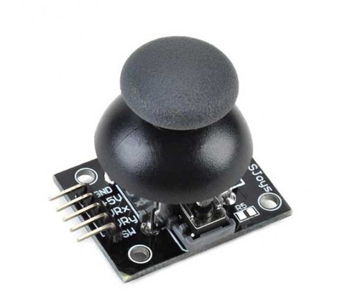
A joystick is an input device consisting of a stick that pivots on a base and reports its angle or direction to the device it is controlling. A joystick, also known as the control column, is the principal control device in the cockpit of many civilian and military aircraft, either as a center stick or side-stick. It often has supplementary switches to control various aspects of the aircraft's flight. Joysticks are often used to control video games, and usually have one or more push-buttons whose state can also be read by the computer. A popular variation of the joystick used on modern video game consoles is the analog stick. Joysticks are also used for controlling machines such as cranes, trucks, underwater unmanned vehicles, wheelchairs, surveillance cameras, and zero turning radius lawn mowers. Miniature finger-operated joysticks have been adopted as input devices for smaller electronic equipment such as mobile phones.
WikiAtmega 328
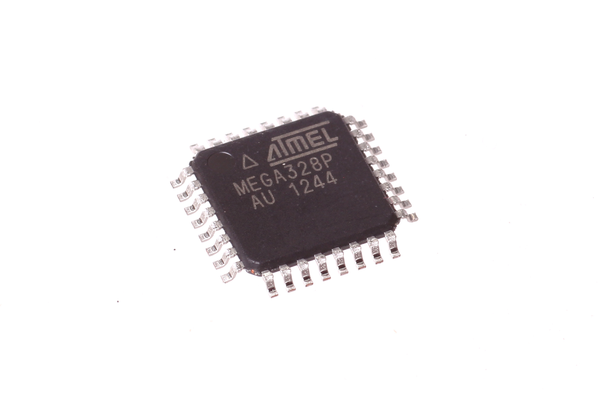
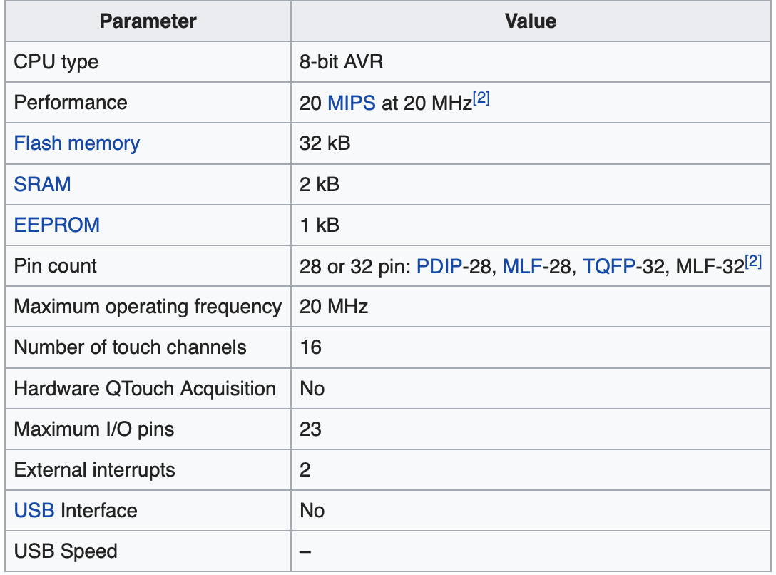
The Atmel 8-bit AVR RISC-based microcontroller combines 32 kB ISP flash memory with read-while-write capabilities, 1 kB EEPROM, 2 kB SRAM, 23 general purpose I/O lines, 32 general purpose working registers, three flexible timer/counters with compare modes, internal and external interrupts, serial programmable USART, a byte-oriented 2-wire serial interface, SPI serial port, 6-channel 10-bit A/D converter (8-channels in TQFP and QFN/MLF packages), programmable watchdog timer with internal oscillator, and five software selectable power saving modes. The device operates between 1.8-5.5 volts. The device achieves throughput approaching 1 MIPS per MHz.[1]
 Wiki.
Wiki.
I made a PCB using atmega 328p which is having 32 legs. I wanted to use this circuit board for my future projects.
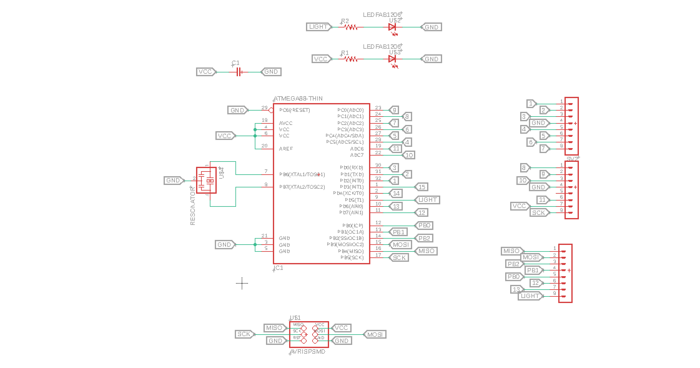
Schematics
I wanted to use this board for my future experiments and also for my final projects if possible.
I have added two LEDs and an external 20Mhz crystal.
Routing the circuit was a difficult task for me.
I used manual routing.
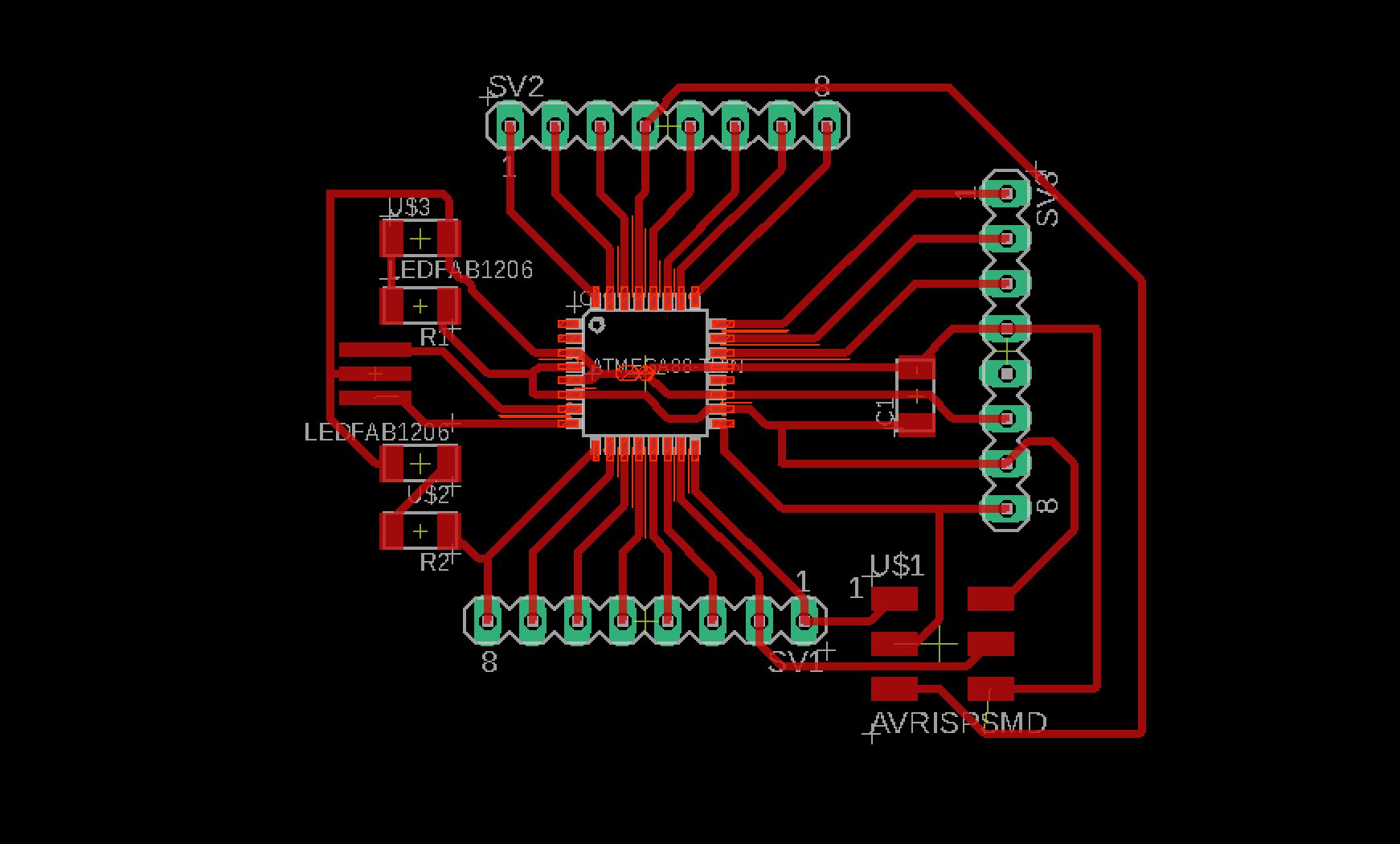
Finished routing after 2 hours. I wanted to make the circuit compact.
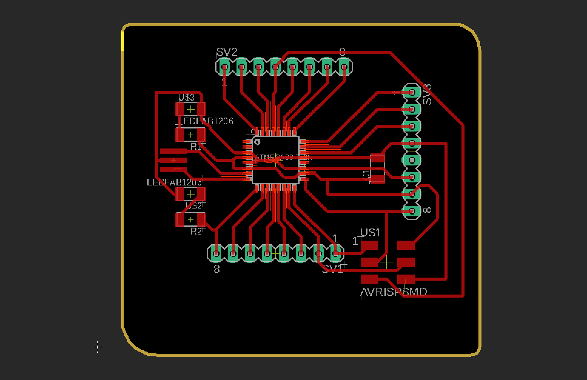
Added round edge square outer cut.
Download files(.sch, .brd & .png) files here
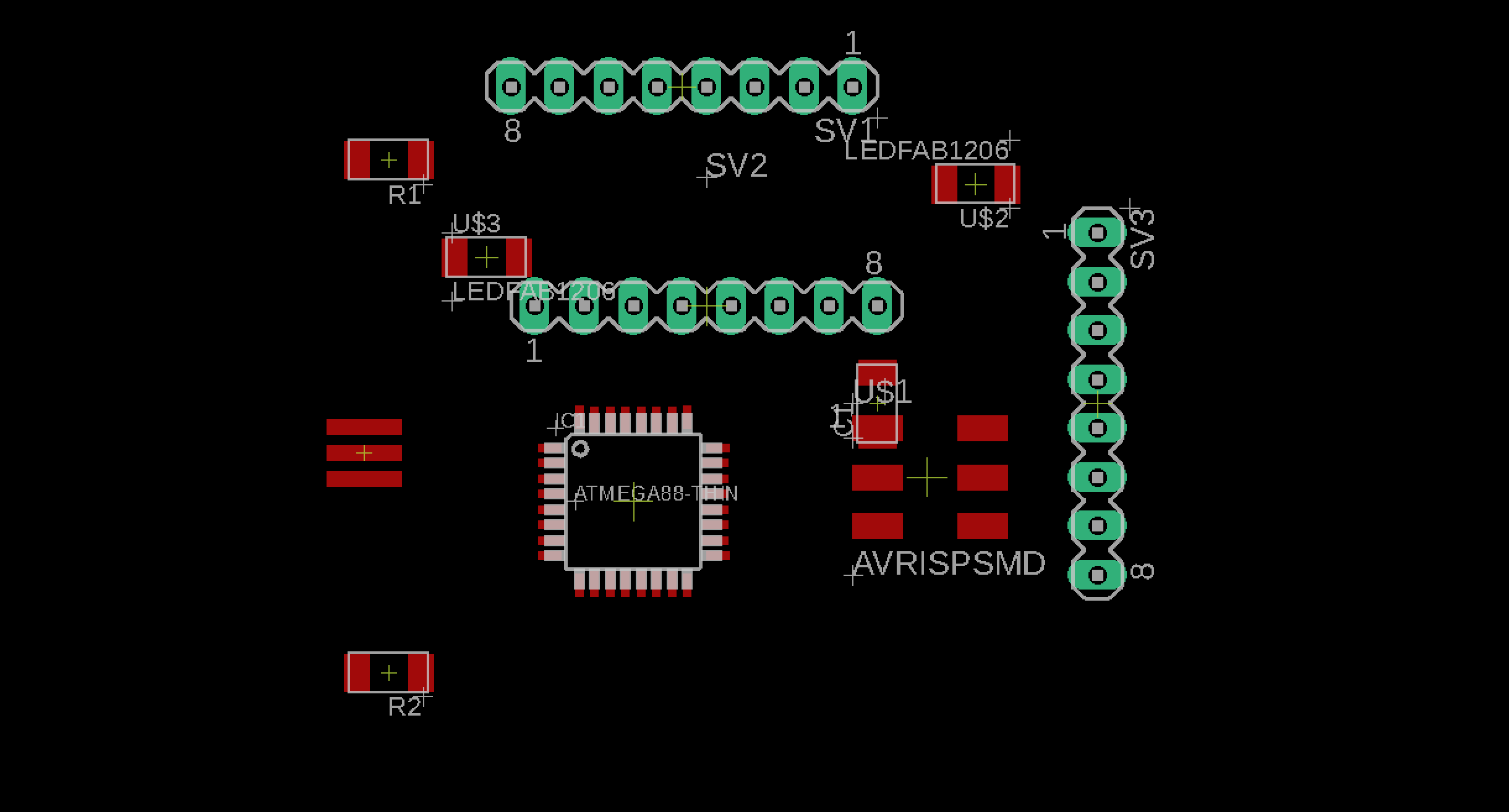
I pulled 24 legs from the circuit board so that I can use this board as an alternative for arduino.
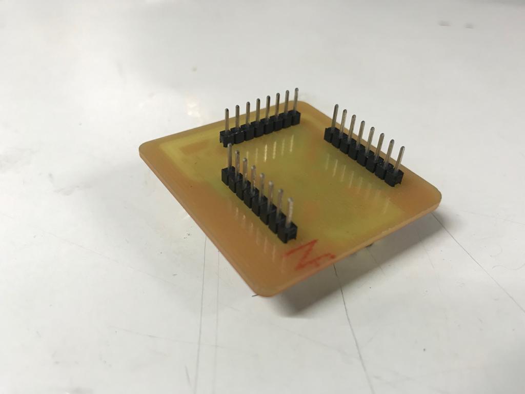
See the male pins.
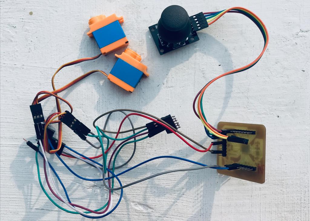
I have connected two servos and a joystick to the board. I forgot to add few extra vcc and gnd pins.
Coding using Arduino
                                #include <Servo.h>

                                Servo myservo1;  // create servo object to control a servo
                                Servo myservo2;  // create servo object to control a servo

                                int pot_1_pin = A0;  // analog pin used to connect the potentiometer
                                int pot_2_pin = A1;  // analog pin used to connect the potentiometer
                                int val_1;    // variable to read the value from the analog pin
                                int val_2;    // variable to read the value from the analog pin
                                int past_1 = 0;
                                int past_2 = 0;

                                void setup() {
                                  Serial.begin(115200);
                                  pinMode(5, OUTPUT);
                                  myservo1.attach(10);  // attaches the servo on pin 9 to the servo object
                                  myservo2.attach(11);  // attaches the servo on pin 9 to the servo object
                                }

                                void loop() {
                                  val_1 = analogRead(pot_1_pin);            // reads the value of the potentiometer (value between 0 and 1023)
                                  val_1 = map(val_1, 0, 1023, 0, 180);     // scale it to use it with the servo (value between 0 and 180)
                                  val_2 = analogRead(pot_2_pin);            // reads the value of the potentiometer (value between 0 and 1023)
                                  val_2 = map(val_2, 0, 1023, 0, 180);     // scale it to use it with the servo (value between 0 and 180)
                                  myservo1.write(val_1);                  // sets the servo position according to the scaled value
                                  myservo2.write(val_2);                  // sets the servo position according to the scaled value
                                  Serial.print(val_1);
                                  Serial.print("    ");
                                  Serial.println(val_2);
                                  delay(15);                           // waits for the servo to get there
                                  if ((val_1 != past_1) || (val_2 != past_2)) {
                                    digitalWrite(5, HIGH);
                                  }
                                  else {
                                    digitalWrite(5, LOW);
                                  }
                                  past_1 = val_1;
                                  past_2 = val_2;
                                }
Arduino code download
Group Assignments
Power (W)
Electric power is the rate, per unit time, at which electrical energy is transferred by an electric circuit. The SI unit of power is the watt (W), one joule per second. For calculating the consumed power, We must know it's
Here is the equation for calculating Power..
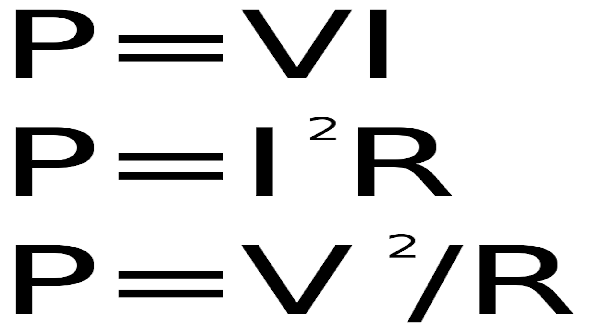
Mesuring Power
As you can see in the above equation, we need to find out the variables. For that we need to test for following using a multimeter
Voltage
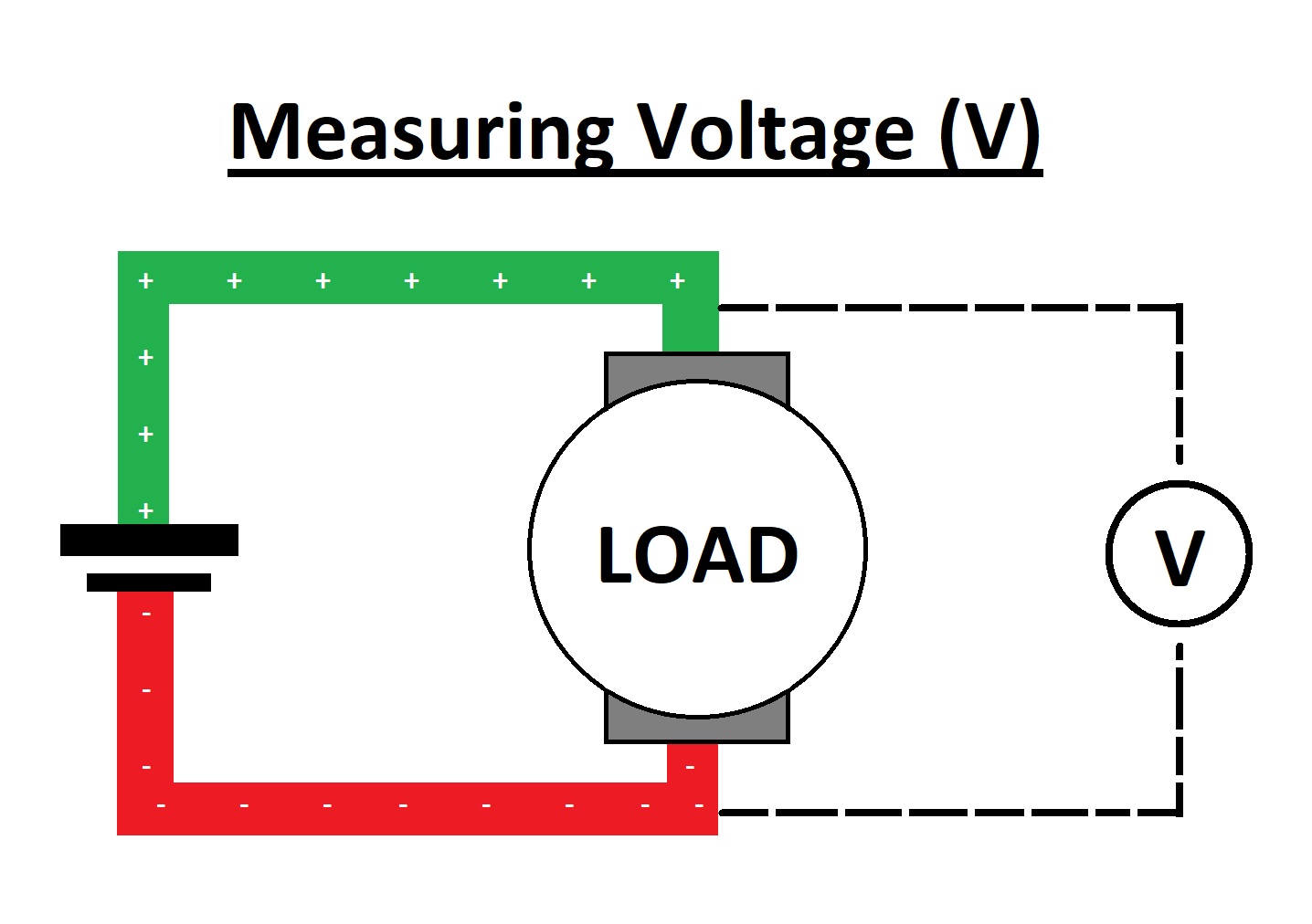
>The voltage is calculated by connecting parallel to the "Load". Here Units of Voltage is "Volt(V)"
Current
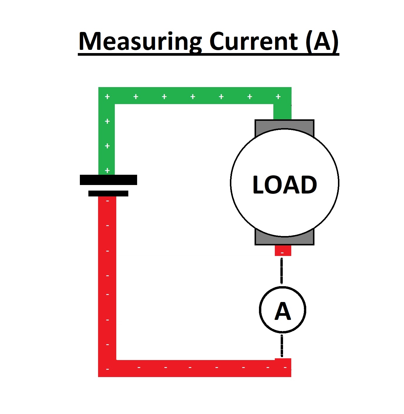
The Current is calculated by connecting series to the "Load".Here Units of Current is "Ampere(A)"
Resistance
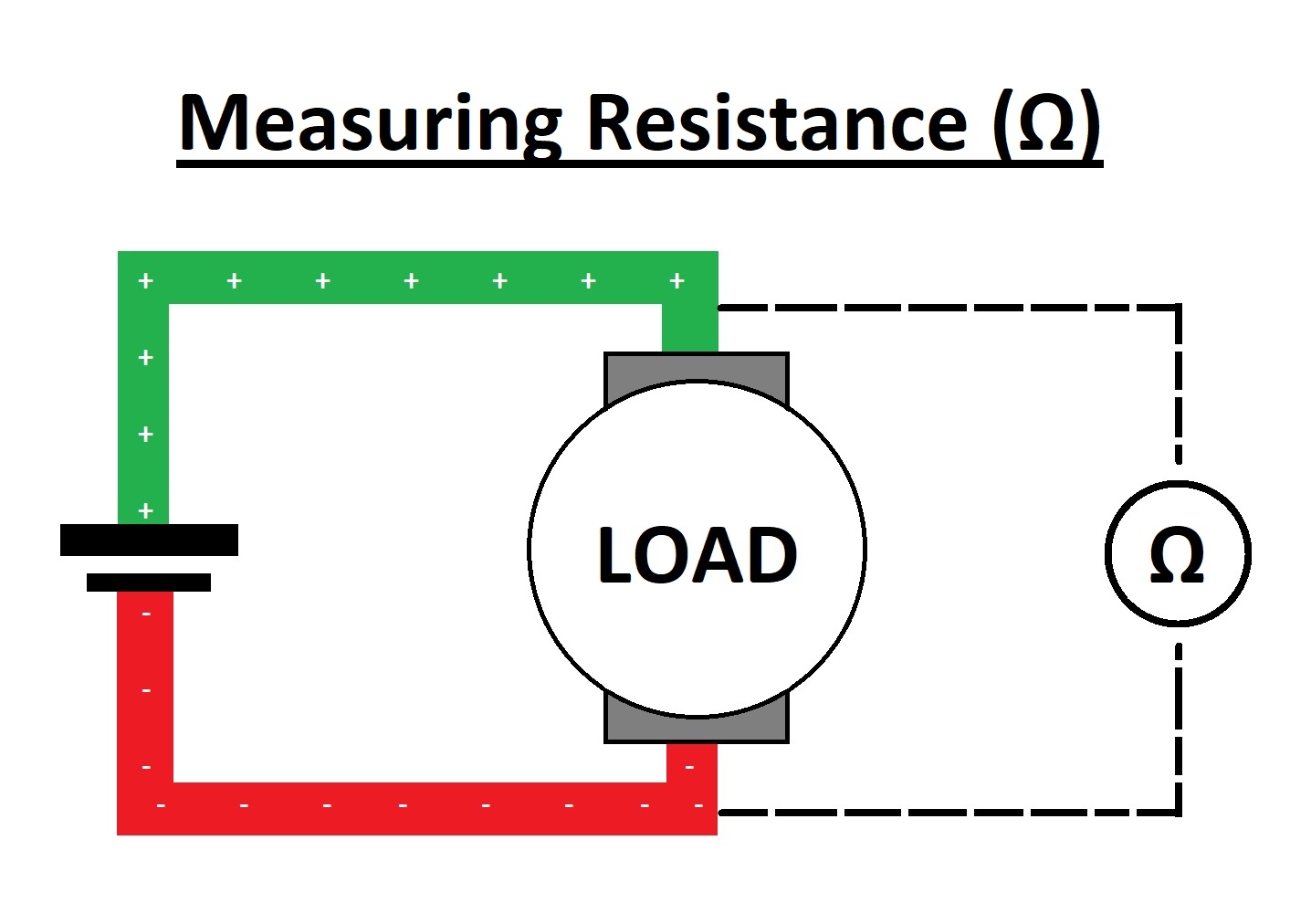
The Resistance is calculated by connecting parallel to the "Load"Here Units of Resistance is "Ohm(Ω)"
So we used a multimeter to find out the variables..
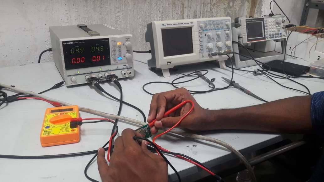
So here we got:
So power can be calculated as:

Substitute values in the equation:
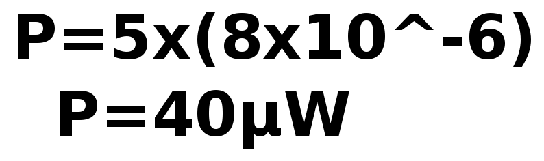
So the power of the output device is "40μW".
By repeating the process and we can find other output devices power consumption...