probe an input device's analog levels and digital signals.
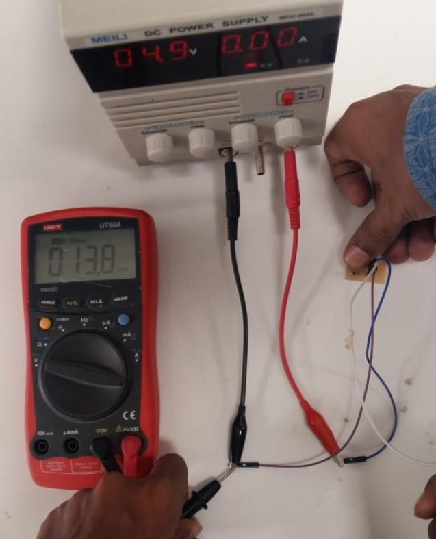
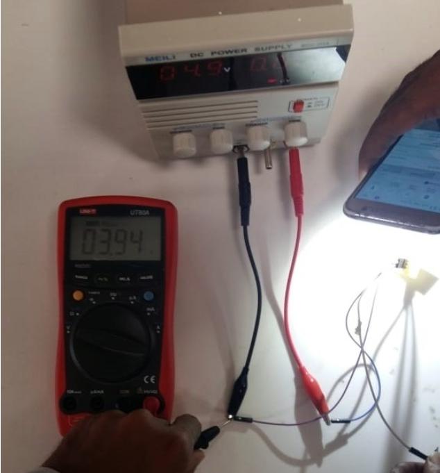
This week's group assignment was to detect the analogue and digital levels of input device we made individually so we started to measure the anlogue voltage levels of photo transitor which was
used by our group-mate Tariq Ahmed in this week's assignment. In group assignment we measured the voltage levels of this component which changes whenever we increase or decrease the intensity of lights on it. We
connected the sensor module to 5 voltage and checked the output on data pin and ground using multimeter. We observed that whenever we increase the intensity of light voltages increase and whenever
we decrease intensity of light voltage decrease. Both of the experiments are shown below in figures (a) and (b) respectively.
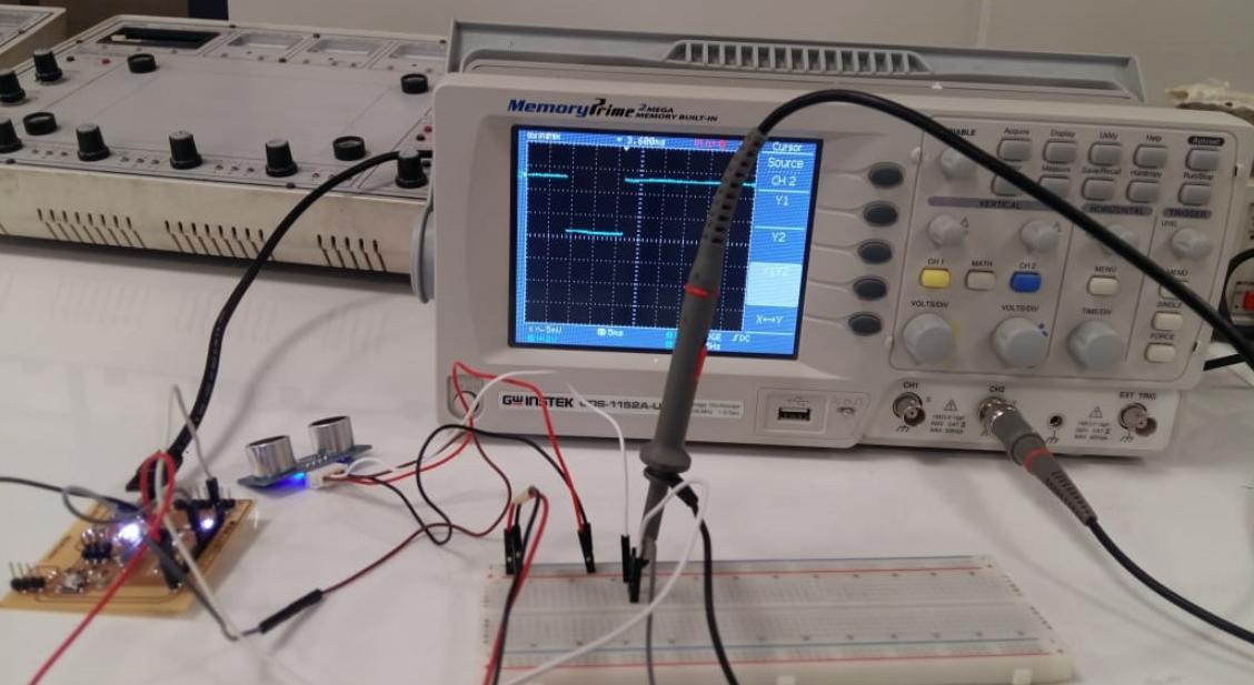
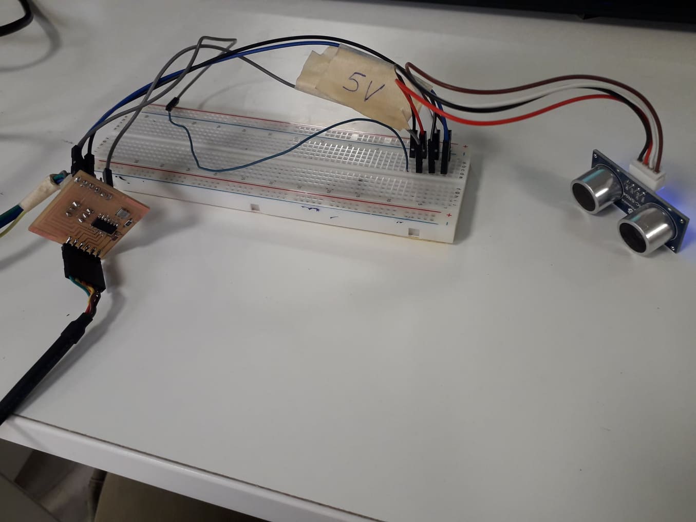
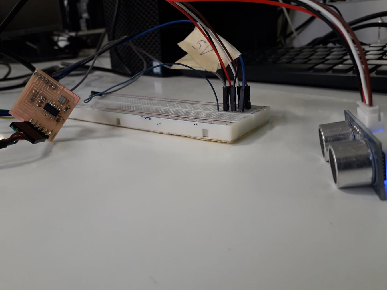
HC SR-04 Ultrasonic sensor is used by ME and another group member in individual task of this week so we used that sensor for detecting the digital signals. We have detected the change in
digital signal in Oscilloscope using arduino Leonardo. A sensor is connected with arduino and the pin of Echo is connected with Oscilloscope. Arduino Leonardo is programmed to detect obstacle
in front of Ultrasonic sensor, when an obstacle is present in front of Ultrasonic sensor we found change in wave in oscilloscope. The captured digital signal of ultrasonic sensor is shown below
in figure. Furthermore the echo pin of sensor is connected to the pin 13 of leonardo which is also connected to led of board. The video given below shows that whenever there is change in signal
led is blinking. The rate of led blink is very fast because digital signal is changing fastly.
Individual assignment
This is the week of the Input devices, On 27th Marh prof:Neil gave us a lecture on input devices and he told us to do work on the different input devices/sensors. So as part of this week's assignment, I need to interface any sensor with the board and using the sensor as an input device, I need to show the results.I have used almost all of these sensors durng my degree courses, I chose Ultrasonic sensor (HC-SR04) as my input device to measure the ditance.
Ultrasonic Sensor
Ultrasonic sensor is also known as Sonar sensor. Basically Ultrasonic sensor is a device which is used to measure distance to an object. This works by sending out a wave which comes back by striking an object, it measure the time elapsed from generating of the wave to bounce back. This way it measures distance from the origin position of the sensor to the object. It follows the given below formula to calculate the distance.
Formula
Designing the Circuit.
I am designing a board for the sensor, so I can interface the board with sensor. I am designing board with the ATting 44 and using a 20MHz resonator.
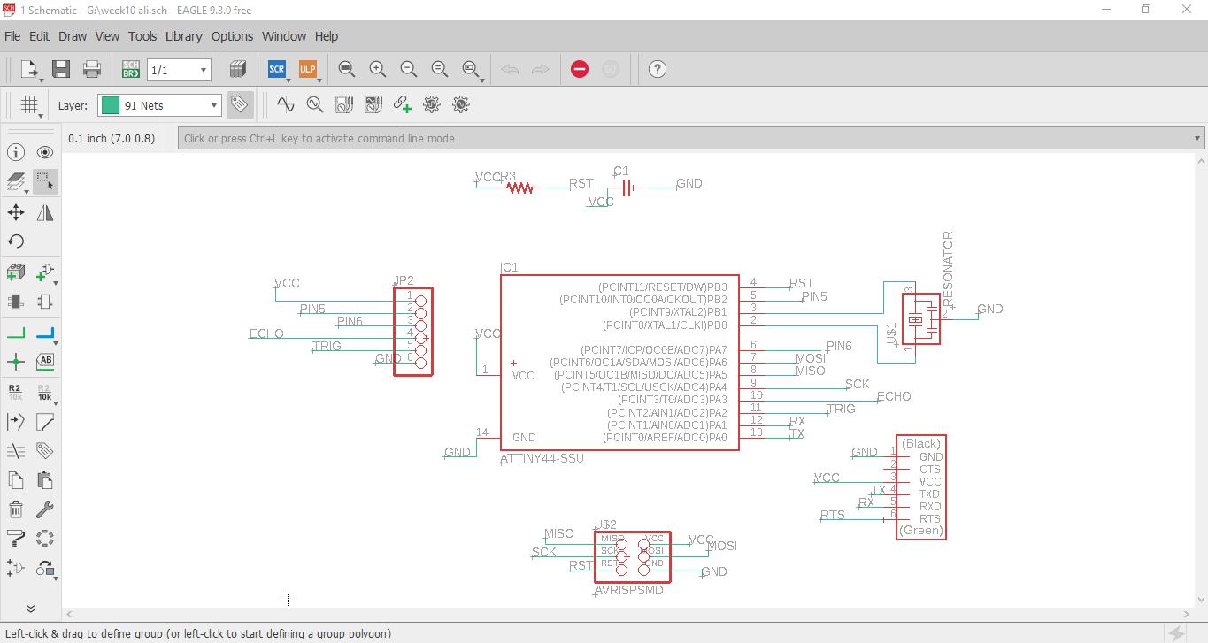
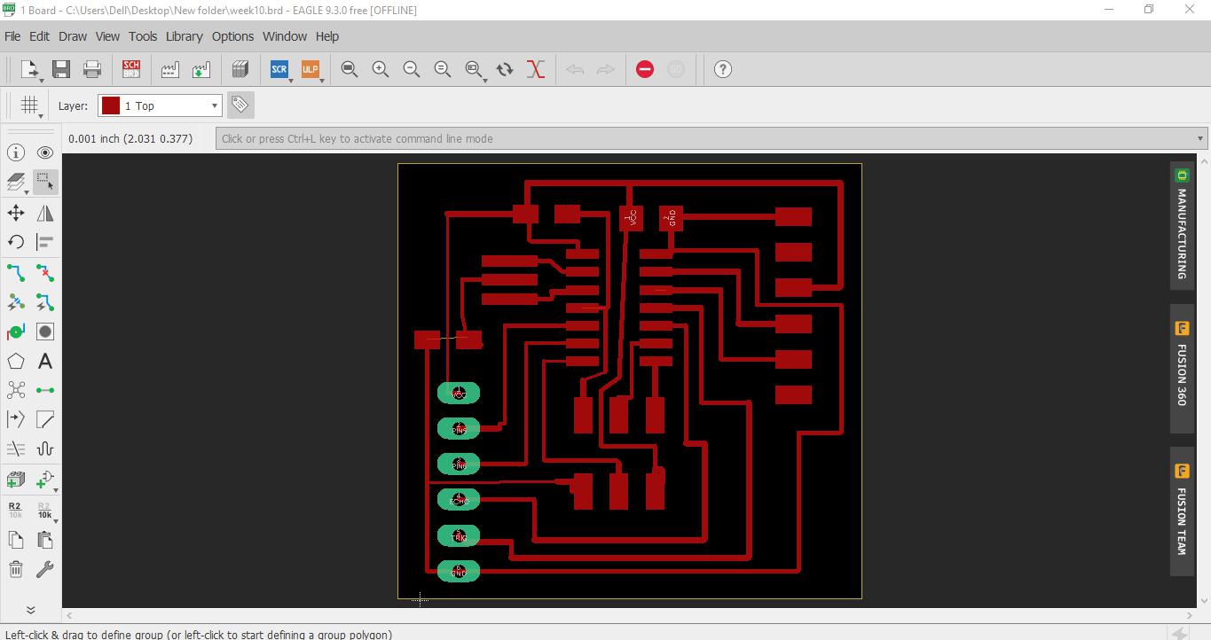
For designing the circuit I used Eagle software.
First I created the schematic by using the components from Fab library and some other components of Eagle.
Schematic
Board
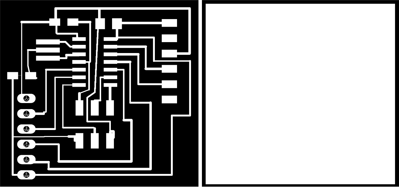
I export it as a .png file
Traces and outline
I connected basic necessary components to the IC, like:
o pin 01 VCC
o pin 02 XTAL1 connected to one side of 20MHz resonator.
o pin 03 XTAL2 connected to other side of 20MHz resonator, and center pin of resonator connected to ground.
o pin 04 10K pull up resistor, and, to RST. Other terminal of the resistor connected to VCC
o pin 05 . connected to 2 pin header for future use connected this wire to simply on a header , may be we use it for any other purpose.
o pin 06 connected to 2 pin header for future use connected this wire to simply on a header, may be we use it for any other purpose.
o pin 07 MOSI/SDA connected to ISP header as MOSI, and also connected to pin no.5 of FTDI header as a SDA .
o pin 08 MOSI connected to ISP header as MISO.
o pin 09 SCK/SCL connected to ISP header as SCK, and also connected to pin no.4 of FTDI header as a SCL.
o pin 10 TRIG Connected to trig pin of Ultrasonic sensor.(connected to pin header)
o pin 11 ECHO Connected to echo pin of Ultrasonic. (connected to pin header)
o pin 12 connected to pin header for future use connected this wire to simply on a header, may be we use it for any other purpose.
o pin 13 connected to pin header for future use connected this wire to simply on a header, may be we use it for any other purpose.
o pin 14 Ground
I have designed this board in this way,so I can use it in future as a microcontroller board.
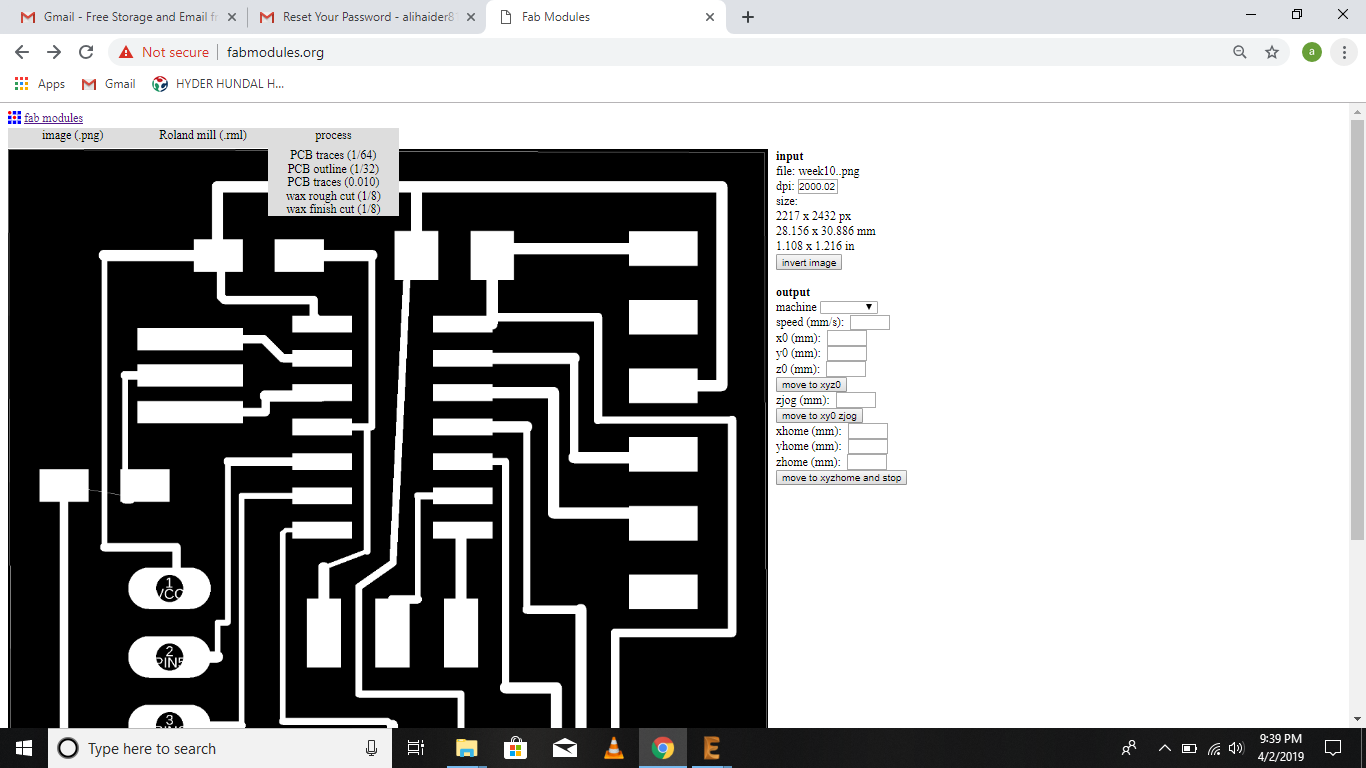
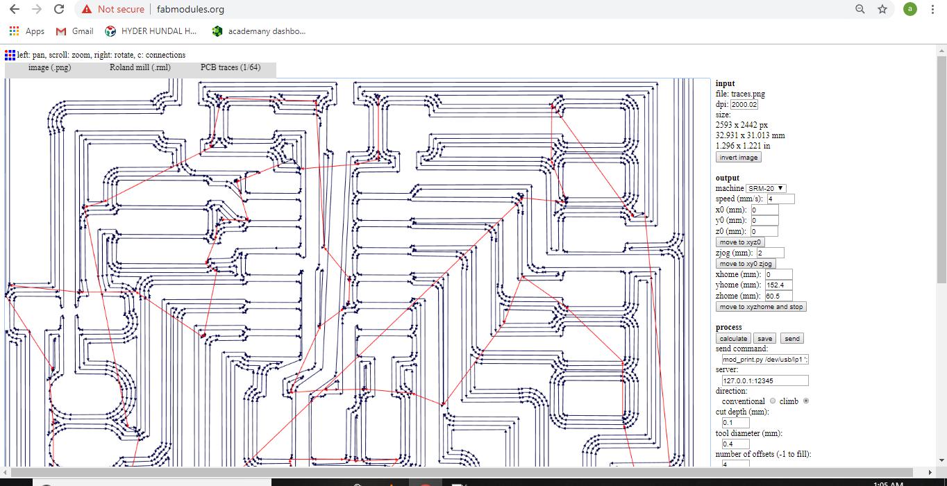
Now I have need of .rml files for the milling process for the PCB board. I am using the fabmodules.
fabmodules
Now I have three .rml files(traces, outlines and drills)
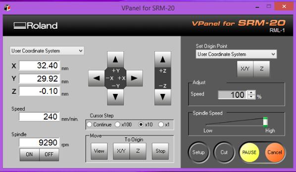
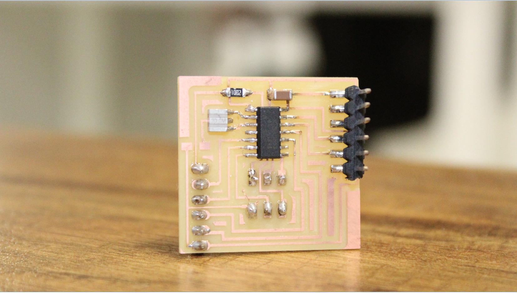
The next step is milling and soldering the board using the Roland SRM-20 machine.
srm-20
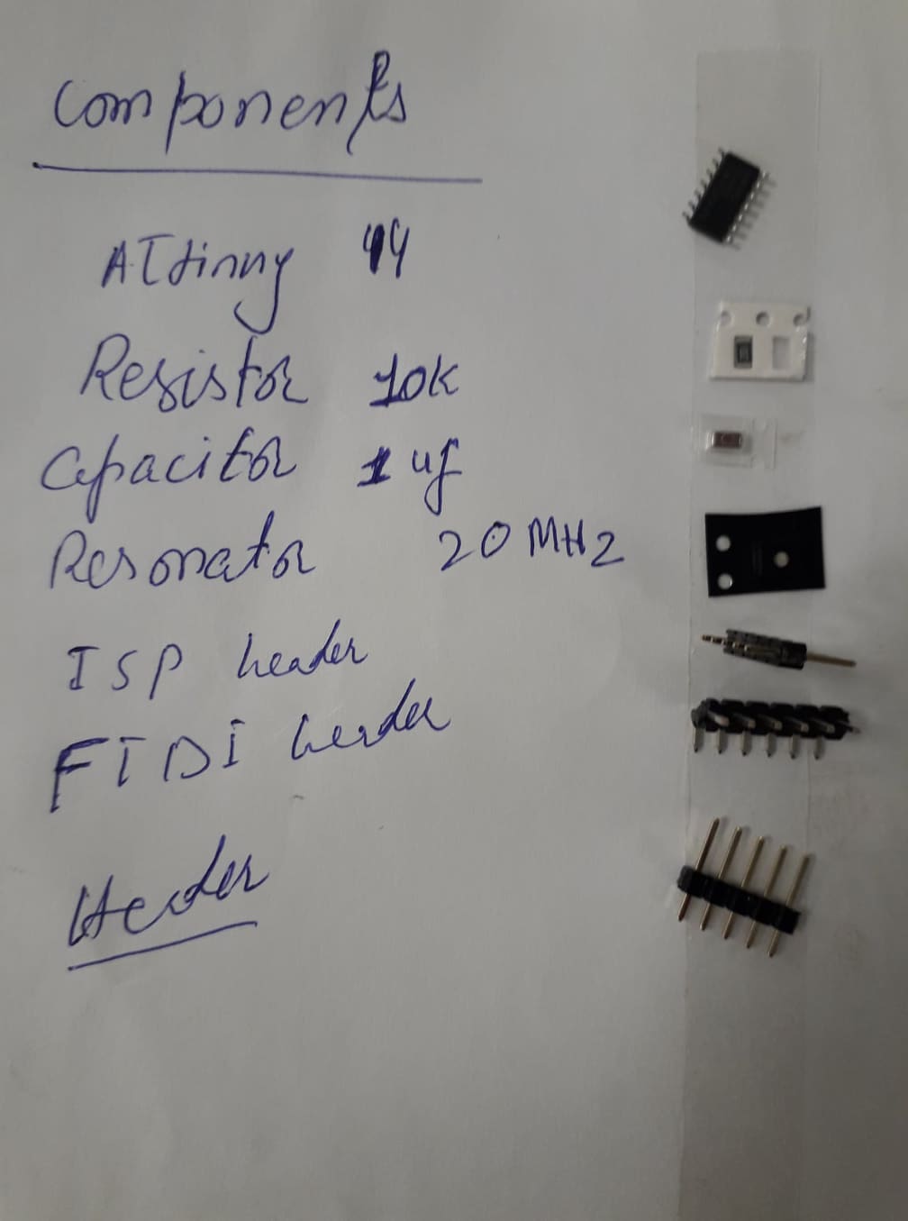
Components
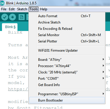
Now the board is ready for the programming. I am using the Arduino IDE for the programming of the Ultrasonic sensor.
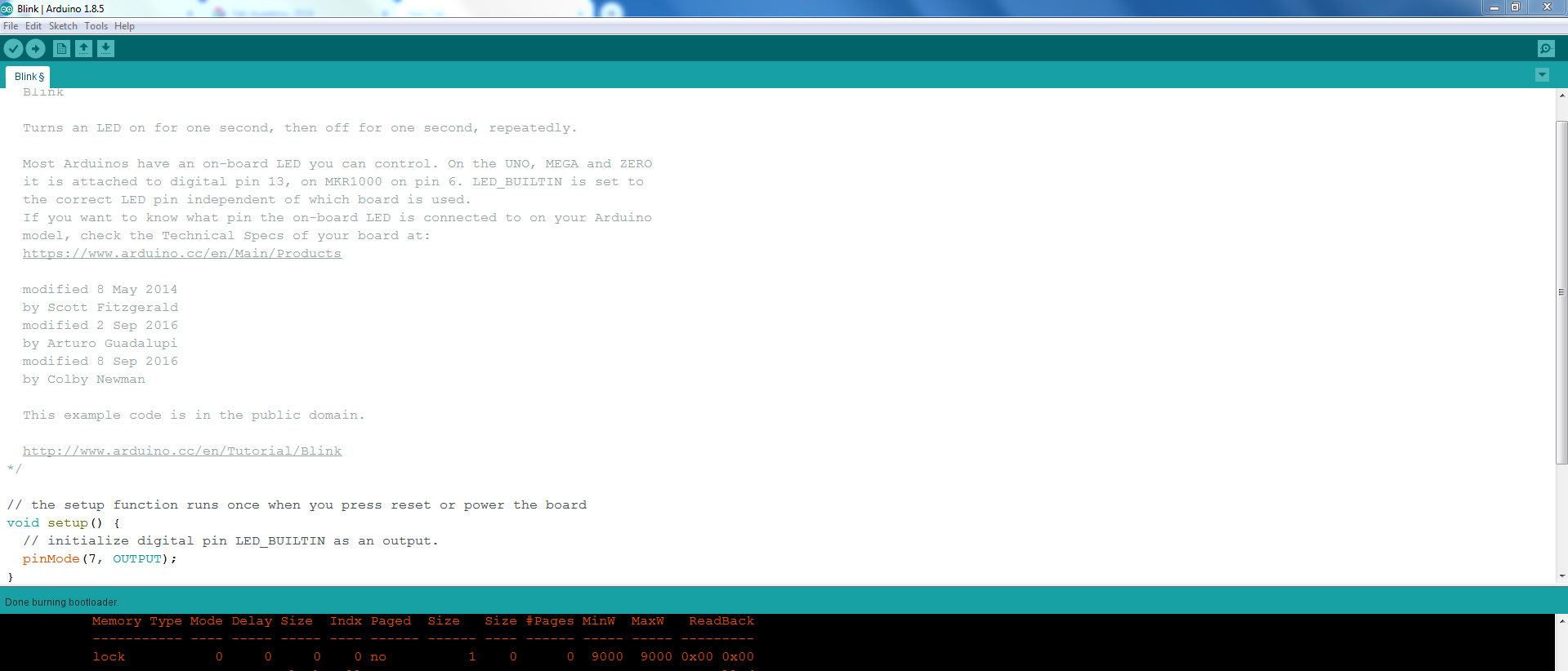
First I have to Burn the bootloader through an ISP programmer. So, here I did it successfully.
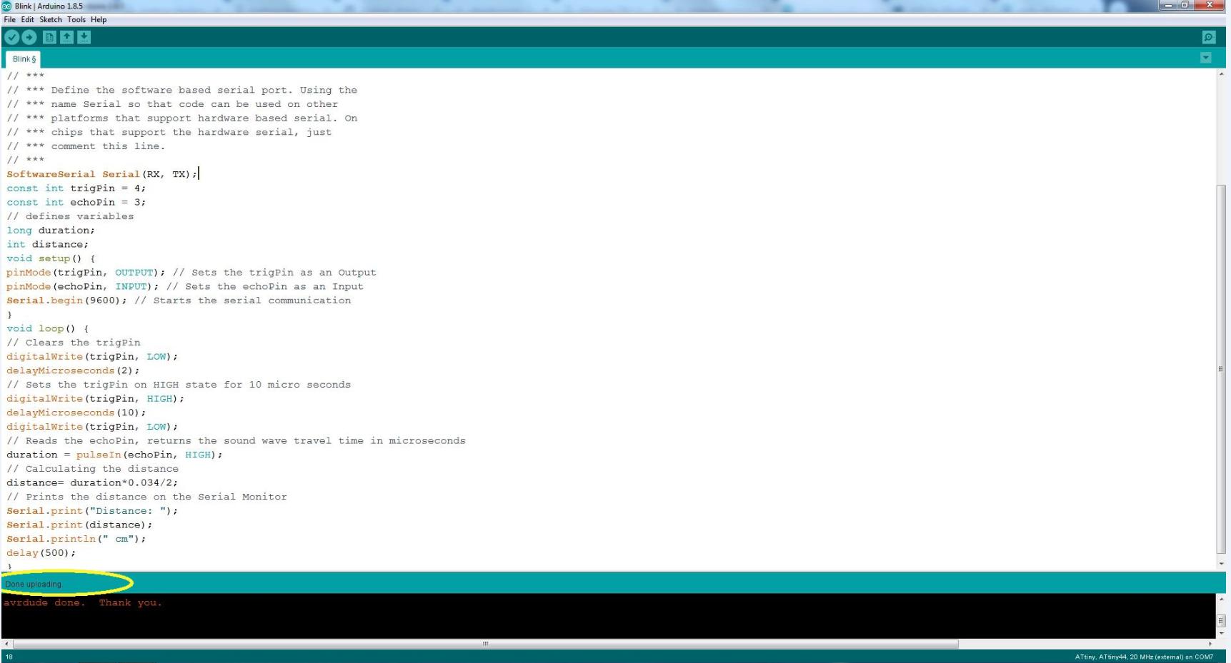
Now I have to write a code for the ultrasonic sensor so I can read the values/distance. I am writting a simple code for the Ultrasonic sensor.
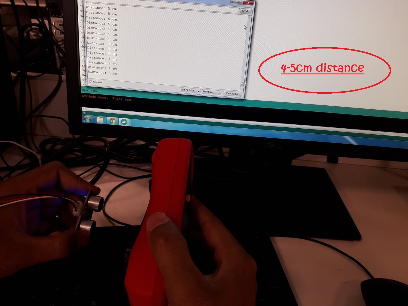
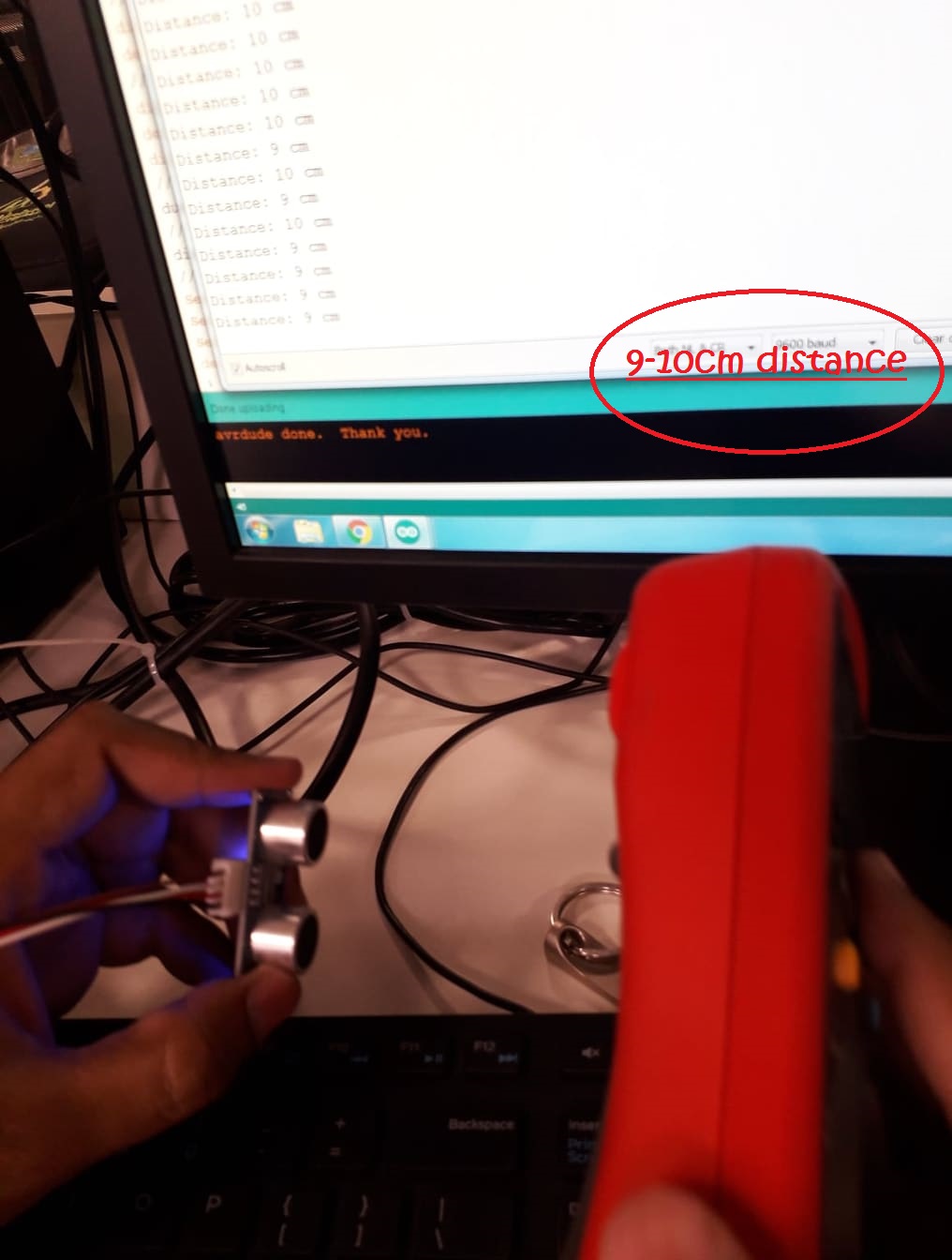
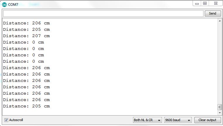
And finally the code is uploaded and the sensor is working accuratly.
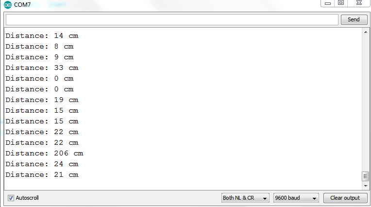
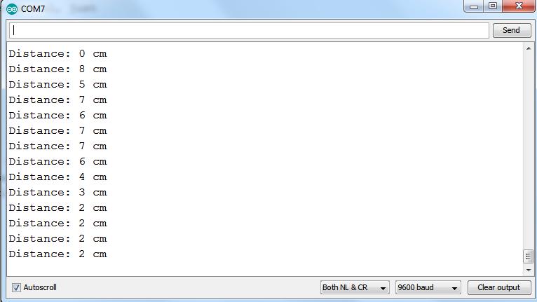
Results
Some Serial Monitor Screen results are shown in snaps.