"Our technologies have outpaced our ability, as a society, to understand them. Now we need to catch up." - Joi Ito
Computer-Aided Design
This week I used a bunch of different tools to digital-design my final project:
- 1. Adobe Illustrator
- 2. Inkscape
- 3. GIMP
- 4. Fusion360
- 5. Sketchfab
- 6. FreeCAD
- 7. Houdini
- 8. Lightworks
Inspirations && Aspirations
NIME - The International Conference on New Interfaces for Musical Expression. I got some inspiritation for the layout of my final project.
The One-Man Industrial Doom Metal Band - Author & Punisher. The musician/engineer behind this band designs and fabricated his own interfaces and musical instruments to achieve some physical exploration of music perfomance, which I found awesome.
BoredBrain - Designers and manufacturers of pedals and patchers. Their designs are beatiful in a punky-geeky way. I'm taking notes for the enclosure and the product design of my final project.
2D
Adobe Illustrator (AI)
I used Illustrator once before, and although I didn't find it difficult, I thought it was a little bit intimidating, because you can do a lot of complex things with it, but I am very interested in learning to use it to make illustrations and diagrams. So my approach with Illustrator is making a sticker out of a photo from the 1.0 version of my console, P_A+L!, so I could fabricate and vinyl cut this sticker next week, when we see Computer Controlled Cutting - Designers and manufacturers of pedals and patchers. Their designs are beatiful in a punky-geeky way. I'm taking notes for the enclosure and the product design of my final project.
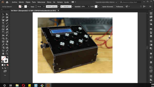
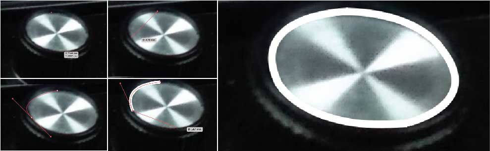
First I created an A4 size file. Then I imported the photograph I wanted to vectorize (Ctrl+Shift+P). It's important that you unselect the Link option to embed the artowrk in the document, so if you move or delete your original file, the same image in AI won't dissapear too. Then I created a new layer and locked the image layer. I used the Pen tool ('P' key) and begin drawing. This image can be useful when your learning the basic tools. The most difficult thing about doing this drawing in AI was to control the handles for the curves. Here are a few tips on how to handle the handles (pun intended). To make a perspective circle like the one from the knobs of the photo, follow this steps:
(Take in consideration that selecting 4 points in a diamond figure is the easiest way to achieve the curved form.)
- 1. Select one point from the curve.
- 2. Select another point on the curve and, without releasing the mouse button, drag the mouse until you find the right curve.
- 3. After releasing the mouse button, you'll see that the next segment is already curved, as AI suggests this form based in the curve you've done. Usually I don't use this curve as it doesn't always follow the pattern you want. If that's the case for you, just click the last point you've drawn to delete this curve suggestion.
- 4. Repeat the same steps for the rest of the curve.
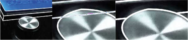
The straight lines are pretty forward to make, so it's not a big deal. Another thing I found a little bit troubeling when I started drawing, was to delete a segment of a line. Here are a few tips on how to do this the easy way:
- 1. Select the Pen with the option of "Add anchor point" ('+' key).
- 2. Add an anchor point close to the intersection where you want to delete the segment. Make sure the seleccted line is the one you want to delete.
- 3. Add another anchor point on the other side, again close to the intersection where you want to delete the segment.
- 4. Add another anchor point, this time in the middle of the segment.
- 5. Press 'A' and select the last anchor point and delete it. It should delete only the selected segment.
- 6. If you need to, adjust the remaining lines by double-clicking the edge points of the lines.
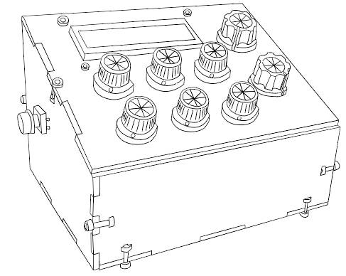
At the end I have this, the drawing of P_A+L! to soon become a sticker! I'm pretty excited about this.
Tip: ALWAYS SAVE YOUR DESIGNS! I think this is prety obvious for any software, but I found (the worst way) that AI closes all the time. On the other hand, everytime it opened again, it automatically saved a copy of the file, so that's pretty good, but it's better to don't take the risk of losing something important.
Inkscape
I want to use more open-source softwares. I have used Inkscape to vectorize images to then lasercut. But I have never designed anything there. So I'll follow a similar process than Illustrator, to make a sticker out of an image. In this case, I'll be drawing the Armadillo, an interactive parametric installation designed by students of the DAFD program and fabricated in Fab Lab Yucatán. This image is simpler than the one I made in AI.
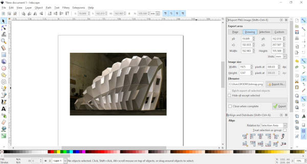
For this I used the Bezier tool (Shift + F6). It's pretty much exactly the same as the Pen tool of AI. I actually find it easier and faster to use because you can end one line and draw another with less commands or clicks. The making of curves is pretty much the same, although I didn't use it in this design.
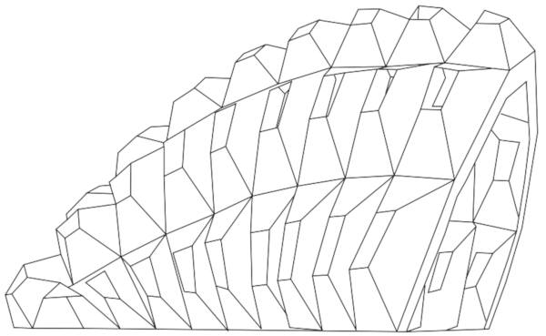
This is my second sticker design! Pretty simple but I really like it.
GIMP
For compressing images I've been using Gimp, that is like an open-source version of Photoshop (PS), or that's what I have seen.
This is a simple guide for compressing images, you can experiment with the values, but this is my standard set up for this documentation:
- 1. Open Image (Ctrl+O).
- 2. Image > Scale Image.
- 3. Width: 600. Height will change according to width if you have them chained together, which I recommend.
- 4. X and Y resolution: 72... although It seems that [this doesn't matter](https://daraskolnick.com/image-dpi-web/) if you're only using the image on the web and not printing it, so you can stay with 300. I actually exported both of them and proved that they have the same file size, which is really important.
- 5. Export As... (Ctrl+Shift+E)
- 6. Quality: 70. Click the "Show preview in image window" to see how it changes the image quality.
- 7. Export.
Sometimes I like to group a couple of images into a single one. For that I found that using AI is easier and faster. First import the images into AI (Ctrl+Shift+P), rearrange them, select them all, right-click > export selection, select JPG 20 format and export.
Update: Right now I'm testing Bimp, an extension that let's you apply GIMP manipulations to groups of images. It's been awesome and helpful so far, I truly recommend it!
3D
Autodesk Fusion 360
Fusion 360 is a cloud-based modelling software. The nice thing about this software is that it has an students version to download for free. It has great integration with Eagle, a software for designing electronic Boards. With this integration you can export your electronic design into Fusion 360 and work into a case or a 3D model of your design.
I have used Fusion 360 since 2017 when I was studying Mechatronics Engineering. I switched to it from SolidWorks, and fell in love with it. Is easier to use and very powerful. I have used the designs to 3D print, lasercut and manufacturing with CNC router.
What I want to do with Fusion 360 this time is to make the 3D model of P_A+L! I already have the 2D design that I used to lasercut the pieces a year ago to fabricate the console. So I'll export this into Fusion 360 and extrude it.
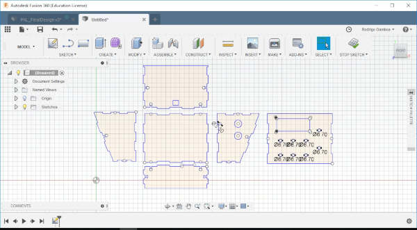
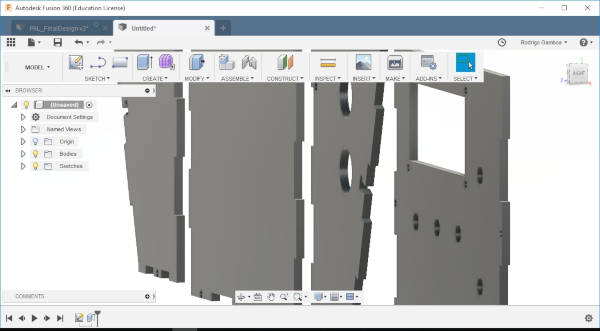
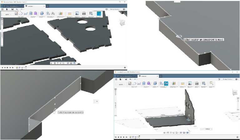
So now the extruded lines are Bodies. You can see them in the left menu. To Join componentes you need to first convert Bodies into Components, so you go to ASSEMBLE>New Component, or you simply click the New Component Icon (the three cubes with a sum symbol). You select the option From Bodies and then select the pieces, you can select many by pressing Ctrl, or by dragging the mouse and selecting the area. You hit OK. On the left menu you should now see the new created Components. Now you can use the function Joint by pressing the 'J' key or clicking the Joint j. Joining components could be a little bit tricky at first, so let's take this example. I need to join these two pieces perpendicularly. So I'll click an specific part of one of the pieces (the one that you want to move) and then click where it will join in the other piece. As I want this piece to move in a 90 degree angle, I'm gonna click the edge of the top side. Note that a little circle will appear to show the different options. Now you can select the edge of the other piece. The pieces will now join and it will appear an option to move to pieces in any direction if thee assembly didn't match as you wanted to. I did the same process for every piece.
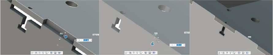
On the last piece, I encountered with the example I mentioned before, where the pieces don't assembly exactly. For this I used the guide arrows to move the piece until it assembles correctly. I moved it 3mm. It's usually an integer number.
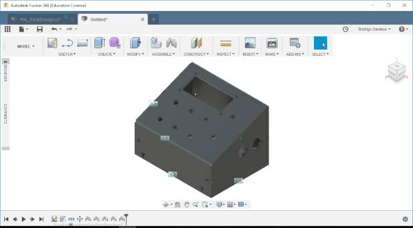
There I have it, the first version of my console P_A+L! on 3D!
Tip: If you don't like to see the dimensions of your sketch all the tim, as me, you can right-click the sketch and unselect Show Dimension.
Here's P_A+L! in Sketchfab! What is Sketchfab you might ask? Well, that's up next.
Sketchfab
I wanted to import this model into my Fab Academy webpage documentation. To do this I need to upload my model to Sketchfab. After signing in, I saw the required formats for the models and compare them with the export types from Fusion 360. It seems that I can only use .igs, .iges. That format worked great for me, but if you want to export to STL from Fusion 360, you can follow this useful guide. I had to do some tweaking to my original design in Fusion 360, like moving it some units so it appears centered in Sketchfab, but not a big deal, Sketchfab let's you configurate a lot of things from their website, like materials, lighting, background image, move and rotate the axises, and what I found most useful, replace the model, so if you make a change in your original model, you don't have to delete and upload again in Sketchfab, just hit the replace button and that's it.
FreeCAD
As in Inkscape, FreeCAD is an open-source parametric 3D modeler that I wanted to use for a long time now. As Illustrator, I found it very intimidating, mainly because I have used SolidWorks and Fusion 360 for a couple of years now, so taking the risk to learn another software seemed pretty big for me. But that is what Fab Academy is all about, so let's do it!
Well, first, for what I understand there's this thing called workbenches. Basically they are pre-settings of tools you would want to use for a specific design. At first I was playing with FreeCAD without any guidence, but quickly I found it very frustrating, so it was time for some tutorials.
Tip: If you close your Combo View (the left panel), just go to View > Panels > Combo View. This may save you some time.
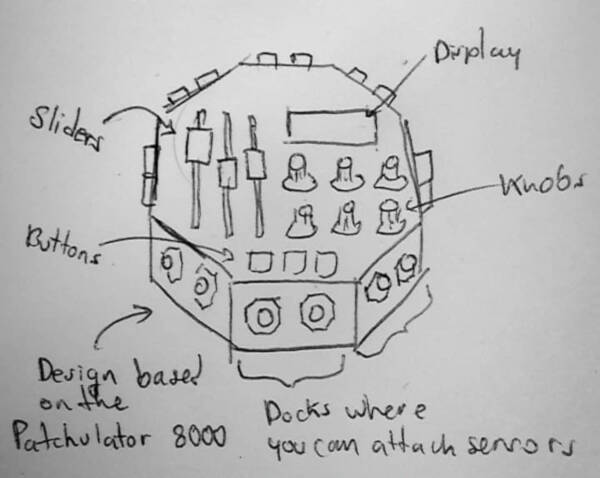
Now with what I've seen in the video, is time to design! I'm gonna try to replicate my drawing:
Here are the steps I followed ro make the 3D designs:
- 1. Select "Part Design" from the Workbench.
- 2. Create new sketch.
- 3. Select the XY_Plane (in my case).
- 4. Create a regular polygon (in my case an octagon).
- 5. Select the center and move the radius.
- 6. Close the editing of the sketch.
- 7. "Pad a selected sketch to extrude". Now I have a 3D figure.
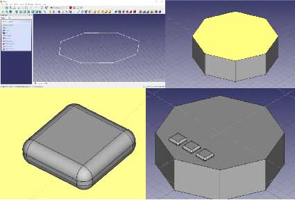
Making the buttons:
- 1. Select "Part" from the Workbench.
- 2. Select "Create a solid cube".
- 3. Select "Fillet the selected edges of a shape". I used 0.2mm.
- 4. Copy the figure and paste it moving the position parameters.
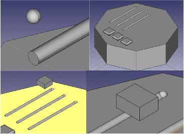
Making the sliders:
- 1. Create a cilinder. Rotate it.
- 2. Creat a sphere. Locate it at the edges of the cilinder.
- 3. Selecting the three objects (cilinder and two spheres).
- 4. "Making a union of several shapes".
- 5. Selecting the whole object and position it at the middle of the upper face.
- 6. Copy it two times, and place them at the sides.
- 7. Select the 3D octagon, and then select 1 of the cilinders.
- 8. Apply "Make a cut of two shapes".
- 9. Repeat setps 18 and 19 for the other two cilinders.
Now I have three round grooves for the sliders.
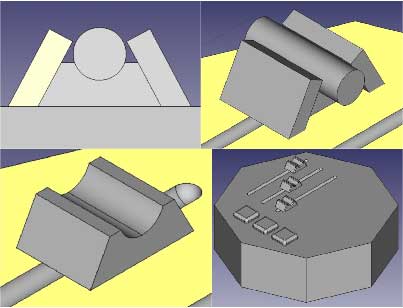
Making the sliders:
- 1. Create cube.
- 2. Create cilinder and position it over the cube.
- 3. Create another cube, transform it and move it in an angle to the main cube.
- 4. "Mirroring a selected shape", XZ plane, move the new object to position.
- 5. Cut the cilinder and the angled cubes to the main cube.
- 6. Copy the result figure to othe two grooves.
Tip: One time, FreeCAD didn't let me select the objects. I fix this by closing and reopening the file.
I used the Fillet and Chamfer options to personalize the sliders. Now I have three sliders!
Making the knobs:
- 1. Select "Create a cone solid". Modify the radius, height...
- 2. Create a cilinder and align it to the center of the cone.
- 3. Fusion both geometries.
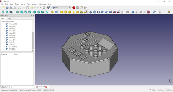
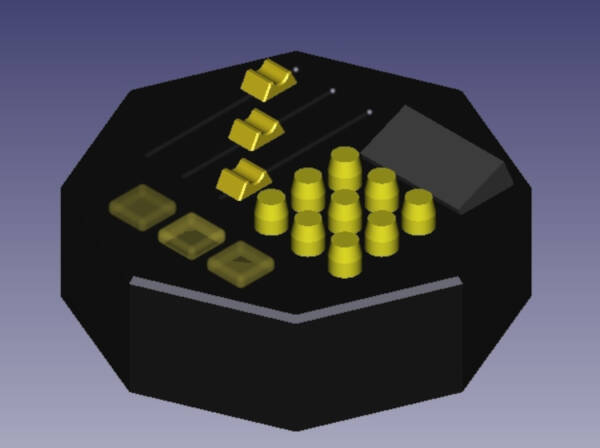
I liked FreeCAD, I'm gonna try to use it more often, although rotating the objects is a very frustrating task, it's probably that I need a lot more practice to master it.
Download the FreeCAD file here!
Houdini
It took many hours of hardwork, but I finally managed to used Houdini! I first got to know about Houdini by reading this fantastic article on Medium, that I truly recommend, and I found it really interesting for a 3D model software to have a procedural nature. As a person fascinated with creative coding, I feel gravitated to this type of software, so I was pretty excited to have a chance to test it. Houdini has a free version called Houdini Apprentice which can be used by students, artists and hobbyists to create personal non-commercial projects.
As a first approach I saw some of this official video tutorials from the SideFX - Houdini website. As I didn't find the outcome of those tutorials interesting enough, I searched on Youtube, until I found this awesome 8-minute tutorial on doing a Disintegration effect. The whole video has a duration of 16 minutes, but the first half is what I found more helpful. Although it's a 8- minute tutorial, I did it in 2 hours, because I'm totally new on Houdini, but it was totally worth it. Here I have the instructions so anyone can follow quickly and have a 3D model destroyed in thousands of particles in a few minutes (or hours). Enjoy!
Tip: As Houdini is procedural design, for the most part you'll have to connect nodes instead of using the mouse to move objects. This is more ina fashion of Grasshopper for Rhino than Autodesk Maya or Blender, so maybe you'll have to re-wired your brain a little bit to get a grasp at it, which is great!
Simple procedural destruction:
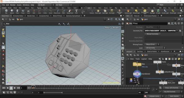
- 1. On geometry node, right-click or tab, type: Geometry, Enter.
- 2. Double-click on Geometry node. Type: Font, Enter.
- 3. Type some text.
- 4. Type: Polyextrude. Join it with the font module.
- 5. Now you can play with the parameters like distance, inset, twist, etc. If you don't see the changes in a solid figure, place the mose over the polyextrude node and select the dispay icon (eye).
- 6. Type: Sphere.
- 7. Change the Primitive Type from Primitive to Polygon. Select the view icon and increase the Frequency to 7.
- 8. Type: Mountain. Connect it to the Sphere node and select the View icon. Play with the parameters to make it look cool.
- 9. Type: Transform. Connect it to the Mountain node, select the View icon. Play with the parameters and move it above and on the left of your text.
- 10. Alt-select the three values of Translate to create a key frame, then move the key frames on the bottom of the screen to 24. Then move the mountain until it covers the Text and again Alt-secelt the three values of Translate.
- 11. Change the frames at the bottom from 240 to 48.
- 12. Type: Boolean. Connect the Polyextrude node and the Transform node to the Boolean node. Change Operation from Intersect to Subtract. Rename it "Bool_Geo".
- 13. Copy and paste another Boolean node, rename it "Bool_Seam". It should be connected to the same places as the first one. Change the Operation to Seam.
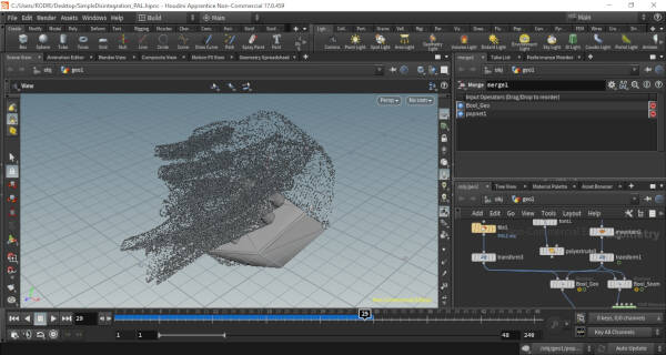
- 14. Type: DOP Network. Connect the Bool_Seam to the first point of the node. For some reason, I can't see the output of this node. Solution: Don't type DOP Network for this tutorial. Type: popnet. This specific node is a DOP Network that has some code embedded on it.
- 15. Double-click on the "popnet" node. Type: Windforce. Place it and connect it between "popsolver" and "output". Change the Scale Force of the Windforce to 5. On the Noise Tab, change the Turbulence to 3, and the three values of Amplitude to 0.5.
- 16. Click the source node (the one on the top). On the Birth Tab, increase the Const.Birth Rate to 30000.
- 17. Click the "popsolver" node. Set the Min Substeps to 3 and Max Substeps to 4.
- 18. Go back to the main nodes wherewe have the Text (press the 'U' key). Select the Transform node and go to the Animation Editor Tab (Next to the Scene View, top left of the screen).
- 19. Drag-Select the last points on the graph. On the bottom move the key frame from 24 to 45. Go back to the Scene View.
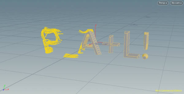
Now you have a pretty cool effect of a disintegration system. You can change the text for whichever you like.
To set a 3D model:
- 1. Type: File. Select your 3D model. I choose an .obj format.
- 2. If you need it resize it with the Transform node.
- 3. Reconnect to the Bool_Geo and Bool_Seam nodes instead of the former Polyextrude.
- 4. Change the size of the Mountain node if you need to cover a bigger space for your model.
To render, I followed this tutorial.
Render
- 1. Set Camera by clicking the top right box on the Scene View.
This is the final result of all this intensive one-sitting session. Hope you like it and find it useful and, with luck, I inspired you to give it a try, It'll be worth it!
Download the Houdini file here! Just load a 3D model on the "file" node, or connect the existing "font" node with the instructions above.
Video
Lightworks
I've used After Effects for making videos, but as I said it before, I want to use more open-free software. Lightworks has a free version too.
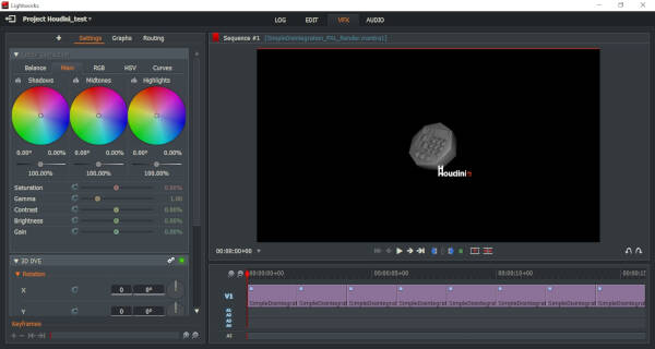
I didn't find Lightworks very easy to use, but this time I especifically used it to make the video of Houndini above, so I didn't follow any tutorials. I'll try to keep using it more so I can master some skill on it and make a tutorial on it.
This week review
So after all of this work, I wanted to share what I did with the global network, so I volunteered myself to speak about the different tools. I speak at 1:14:43 time.
Fab-20190206B_Review02: computer-aided design from Academany on Vimeo.
Files
- PAL illustration .ai (Adobe Illustrator)
- PAL sticker .pdf
- Armadillo sticker .svg (Inkscape)
- Armadillo sticker .png
- PAL 3D .f3d (Fusion 360)
- VJ Console .FCStd (FreeCAD)
- VJ Console .stl
- Procedural Model Destruction .hipnc (Houdini)