Back to Mónica Pedro ←main page ←Assigments
individual assignment:
    add an output device to a microcontroller board you've designed,
         and program it to do something
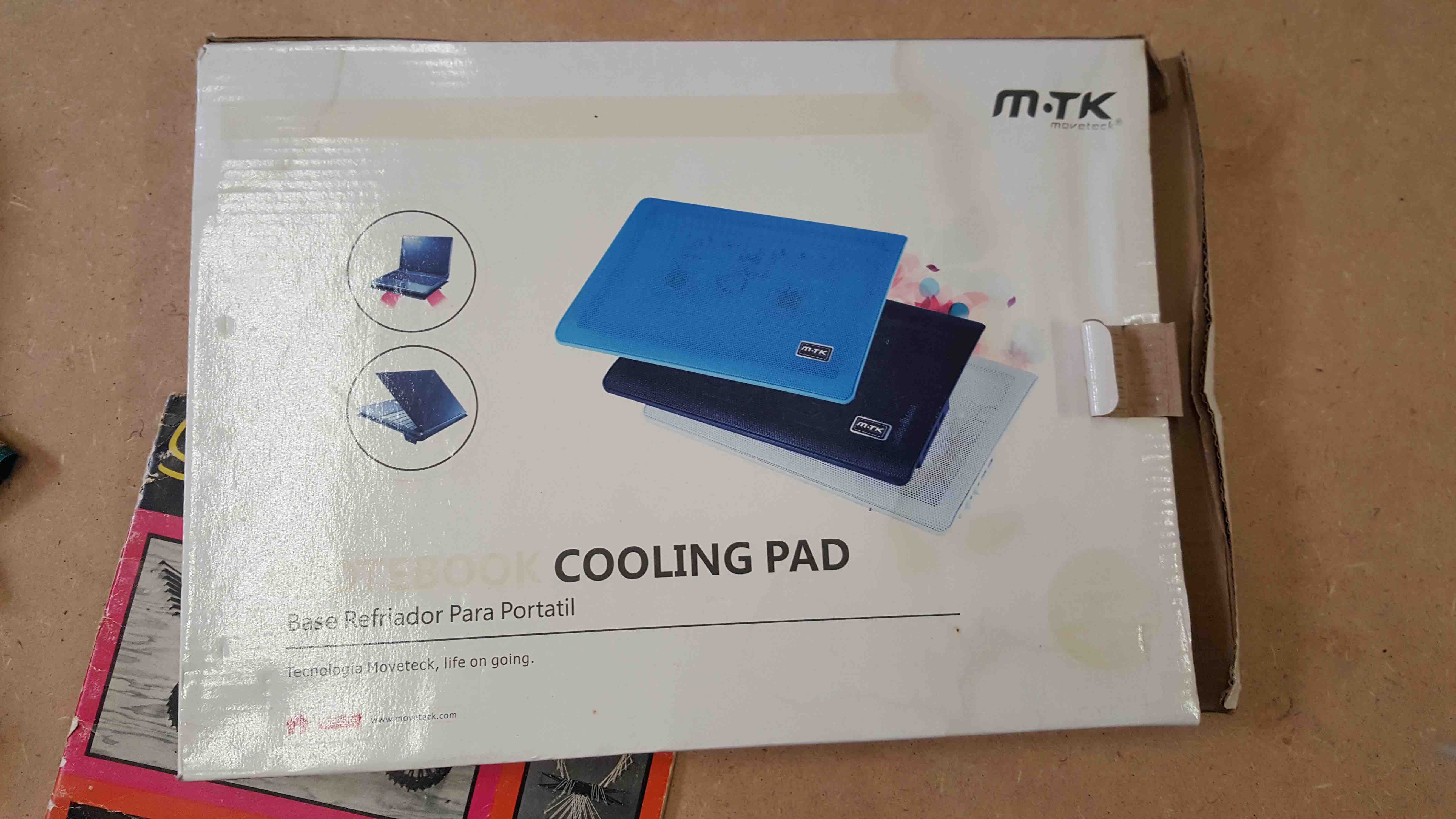
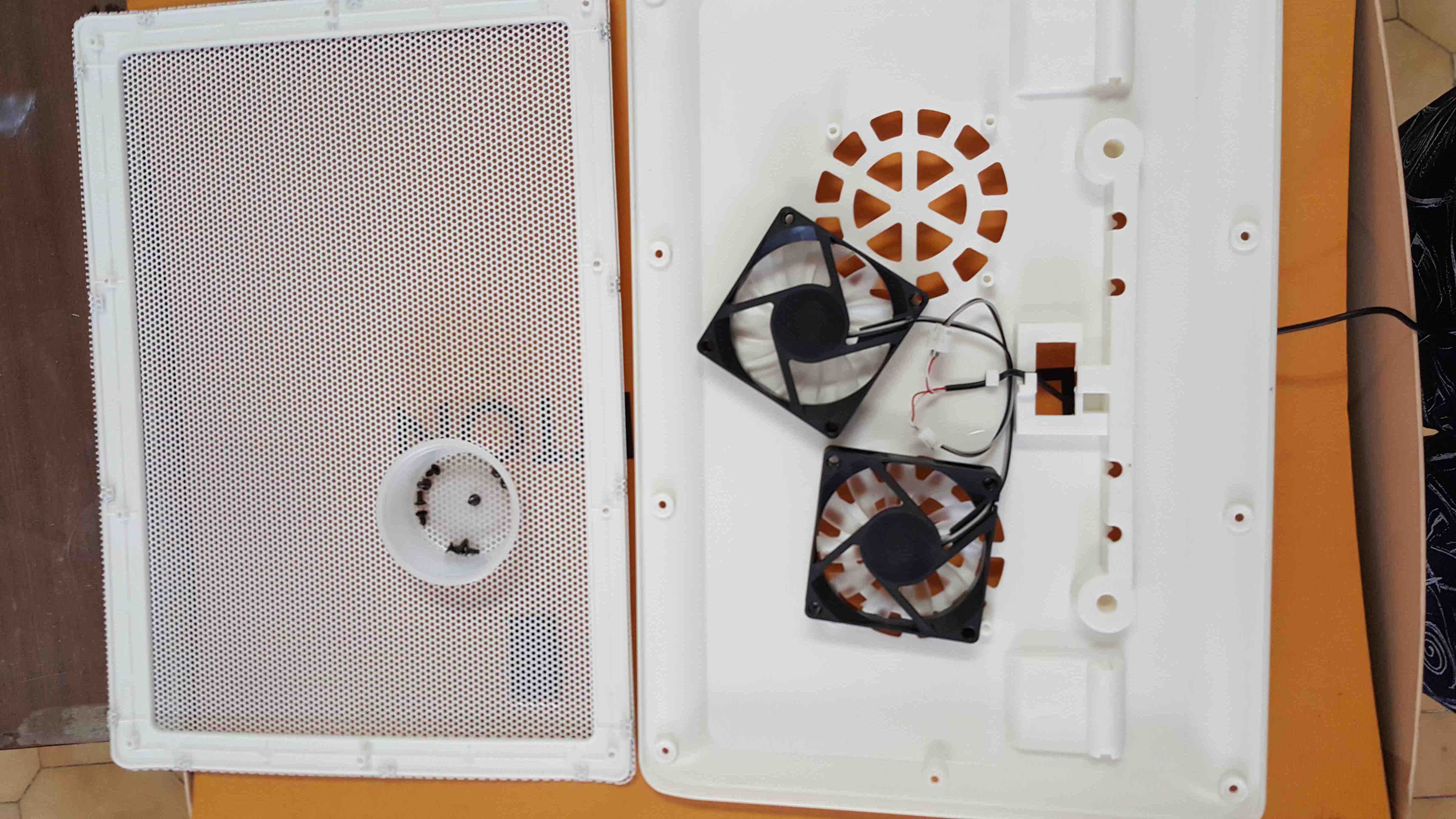
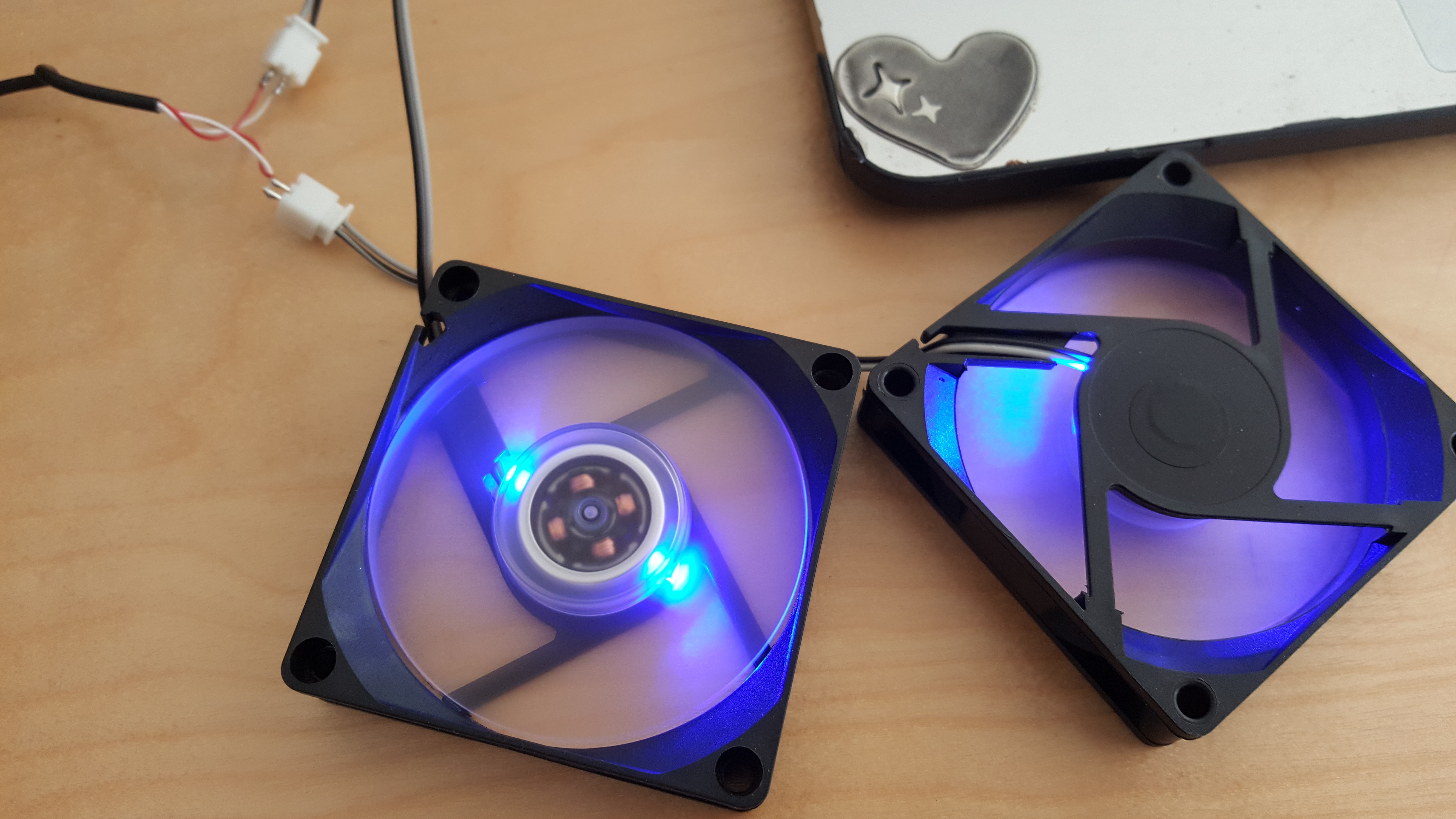
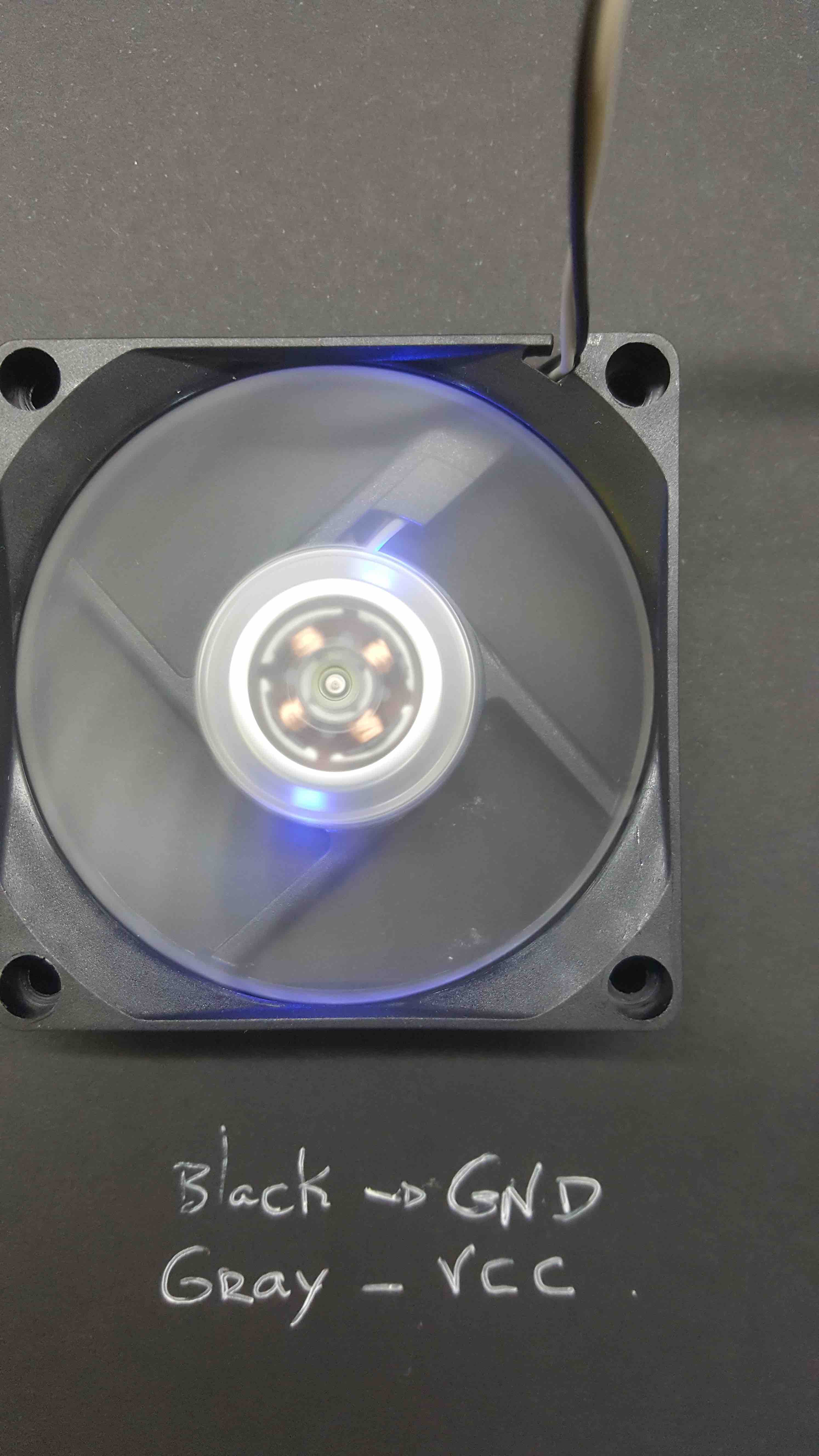
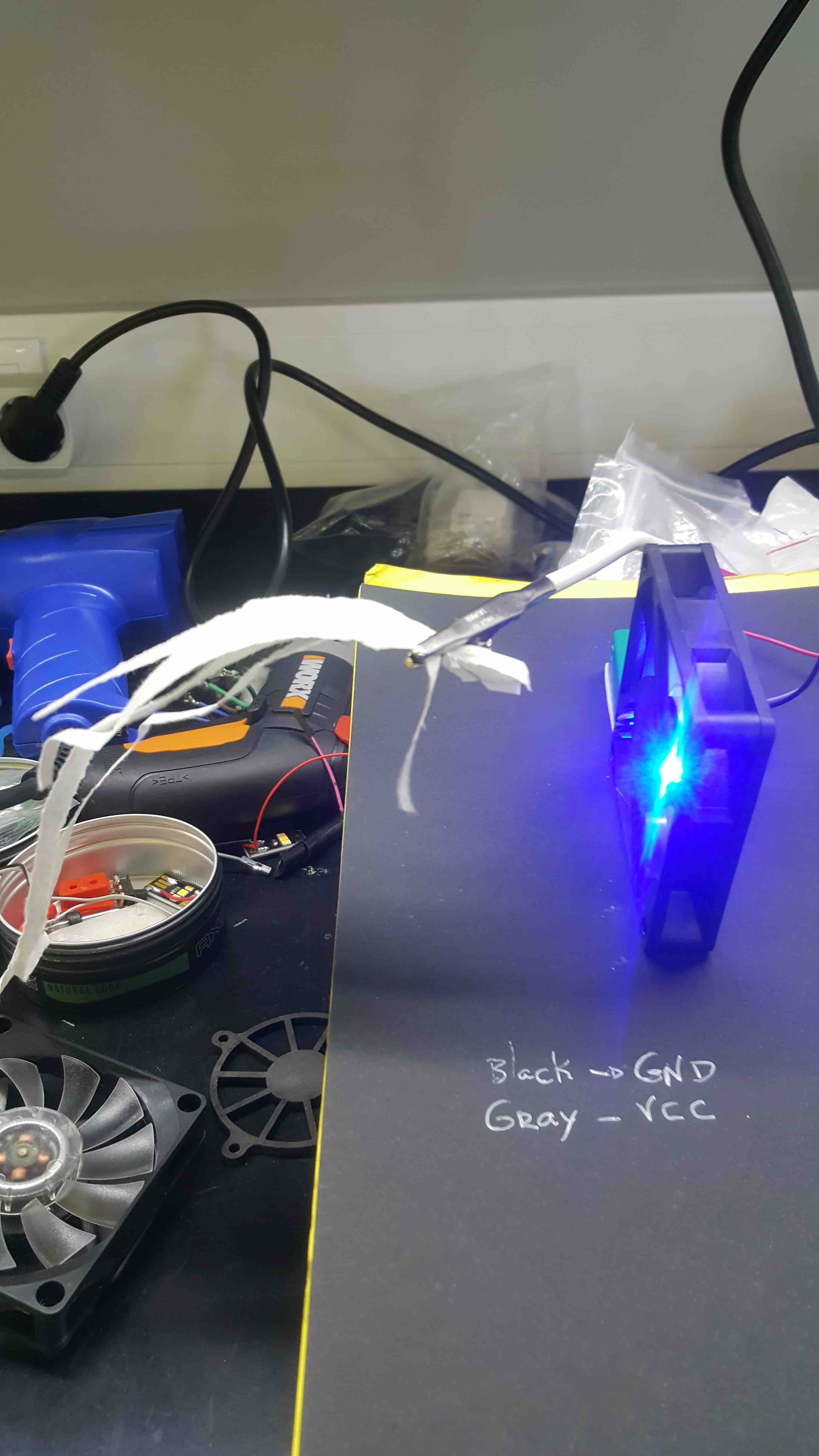
I'd sow that I'd some out-of-use Fans in my homeLab:
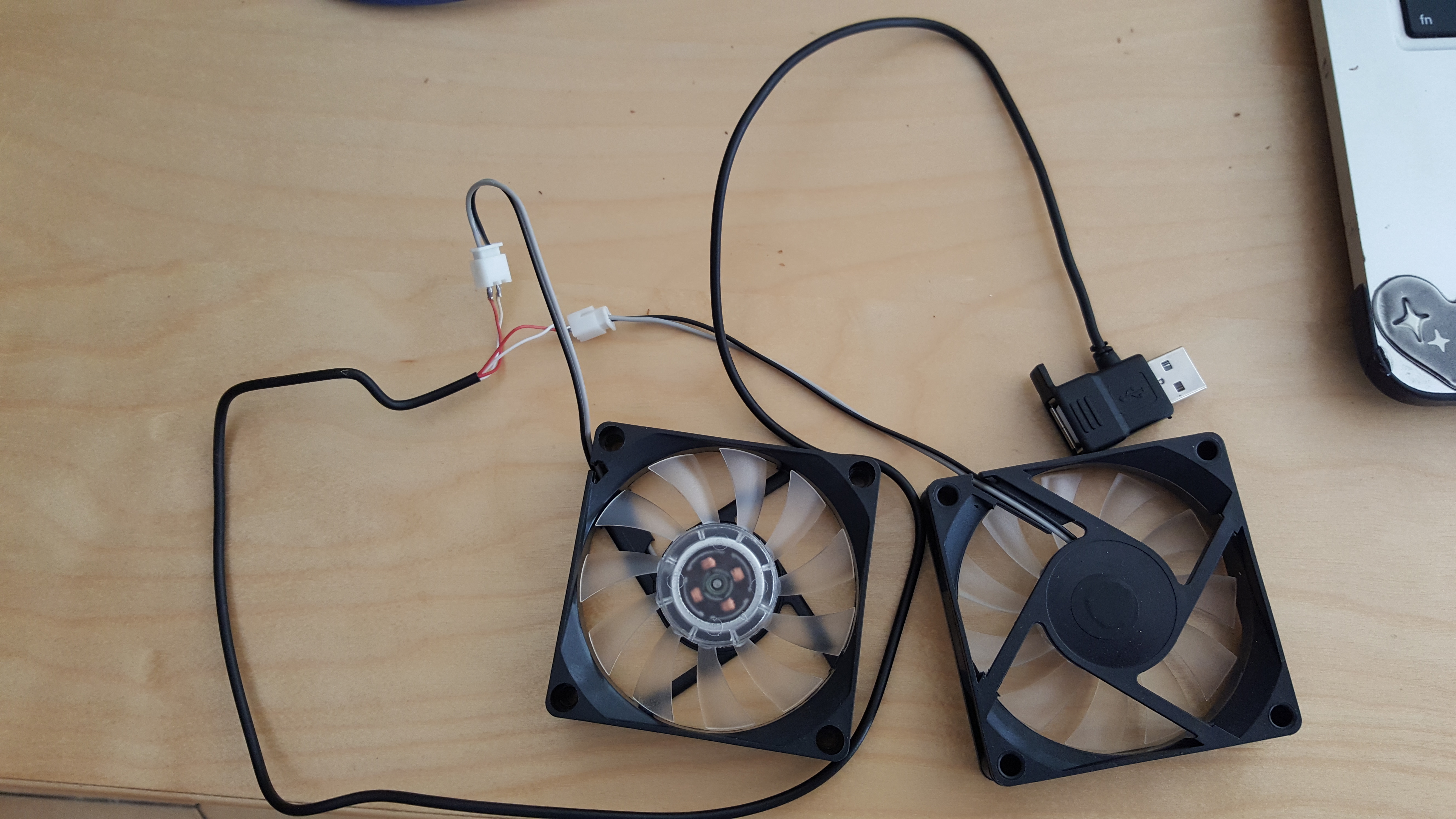
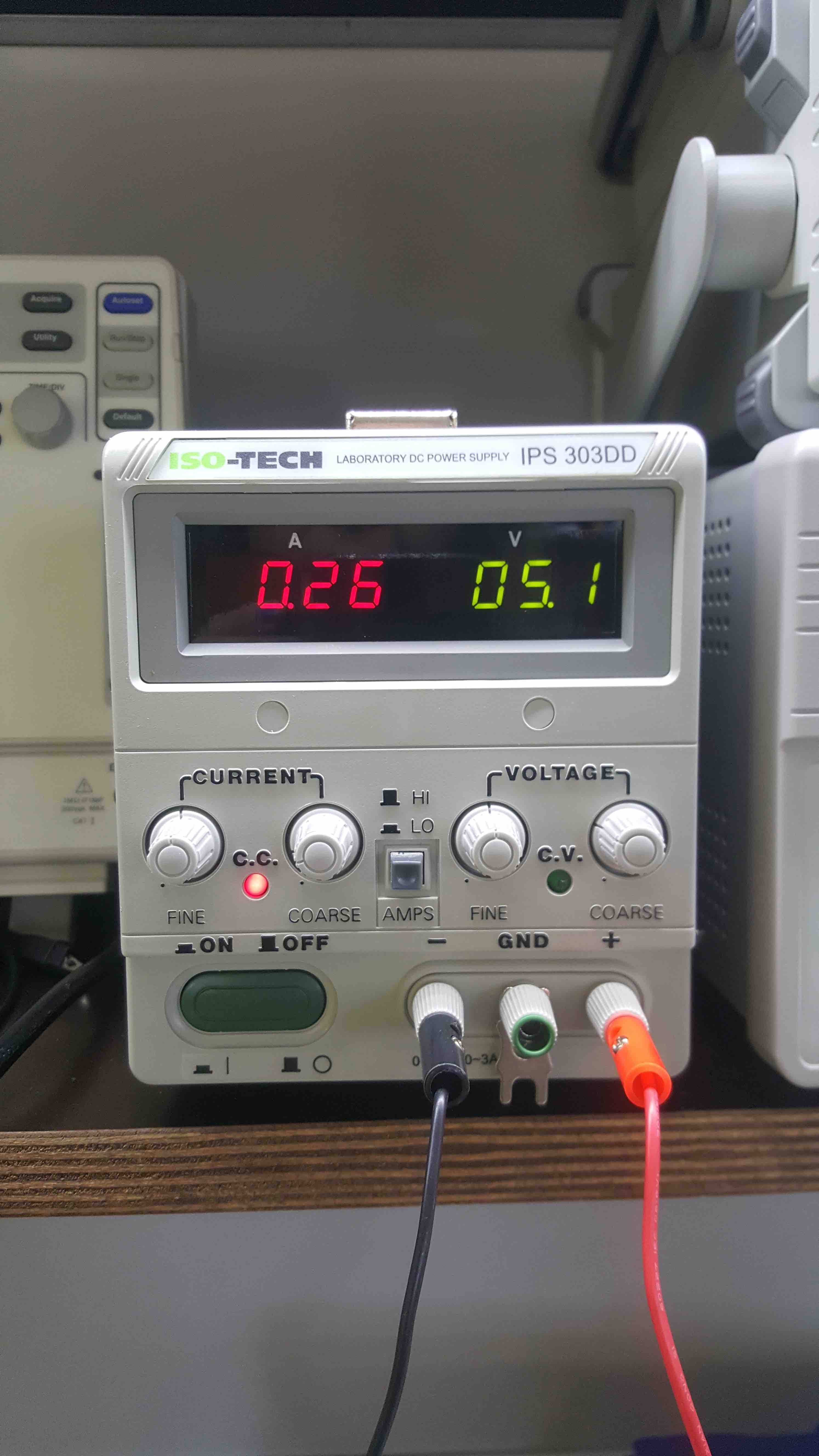
used the ISO-TECH Laboratory DC Power Supply IPS 303DD
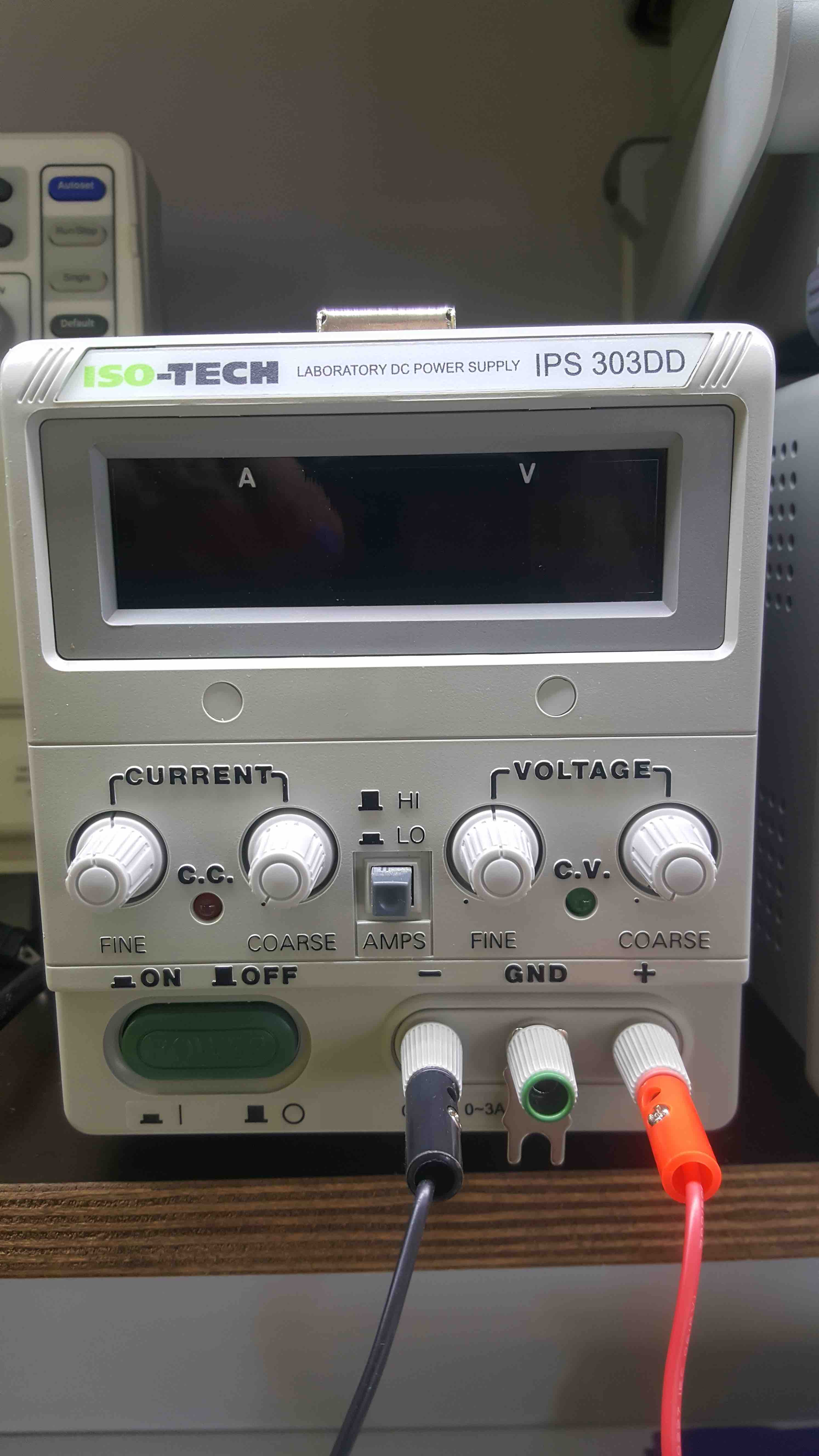
Connected the GND and VCC
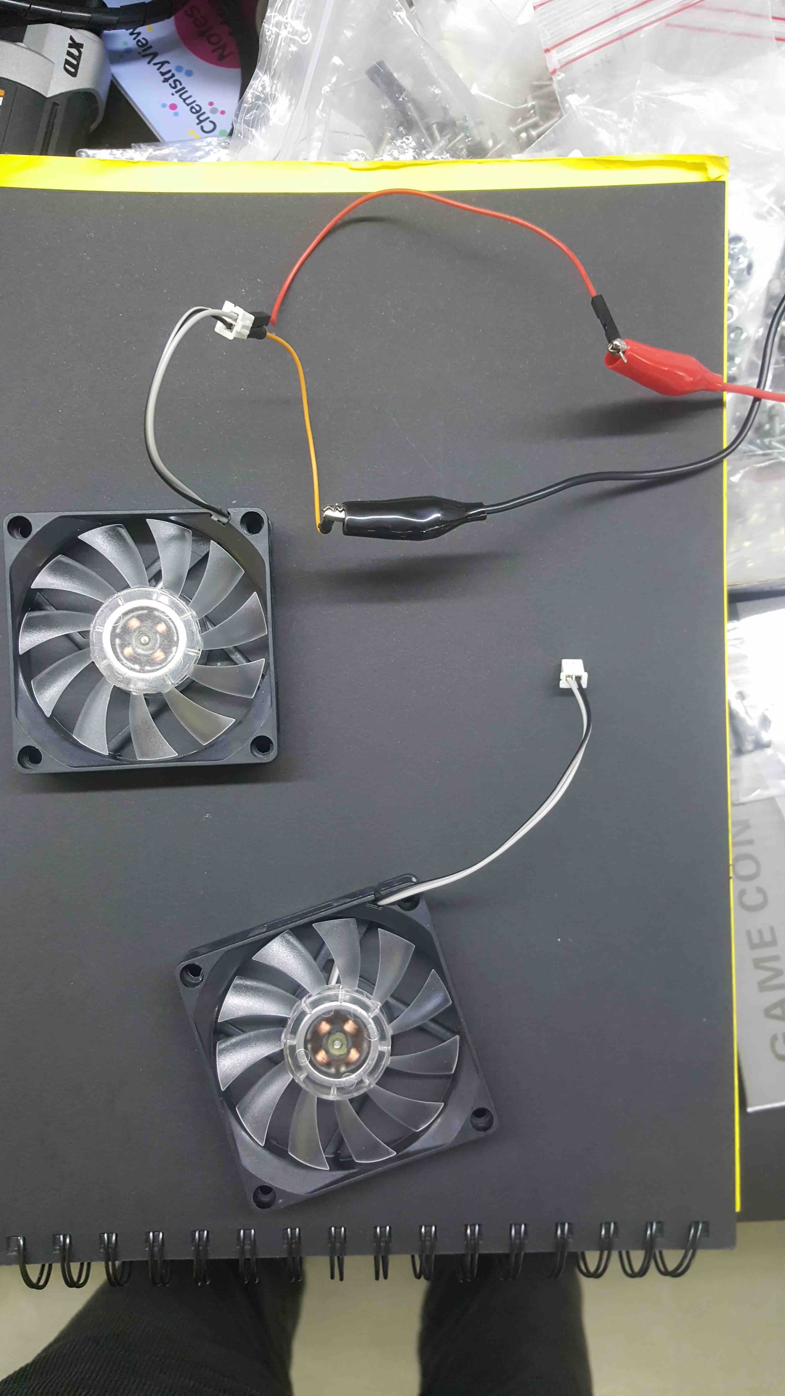
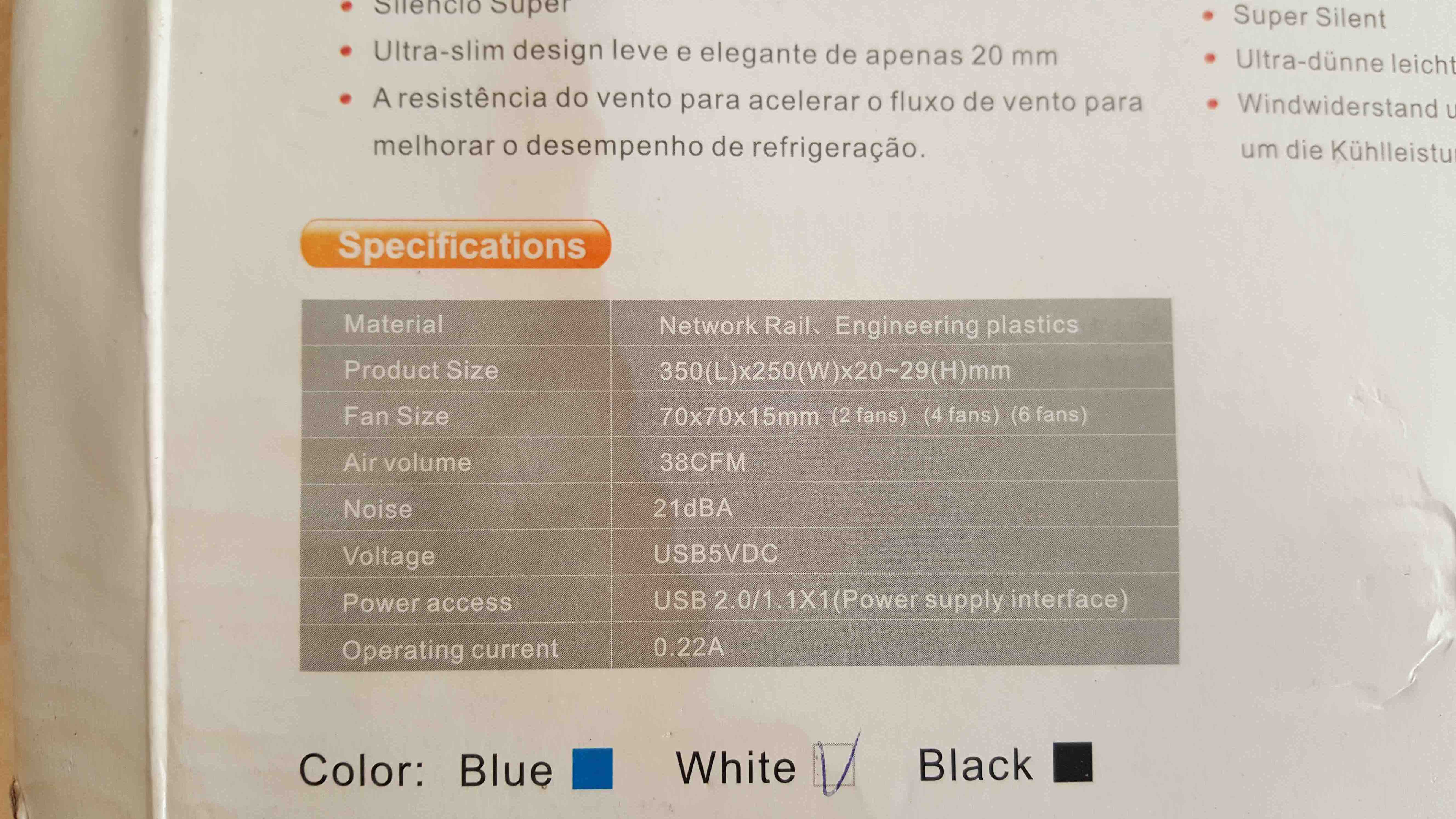
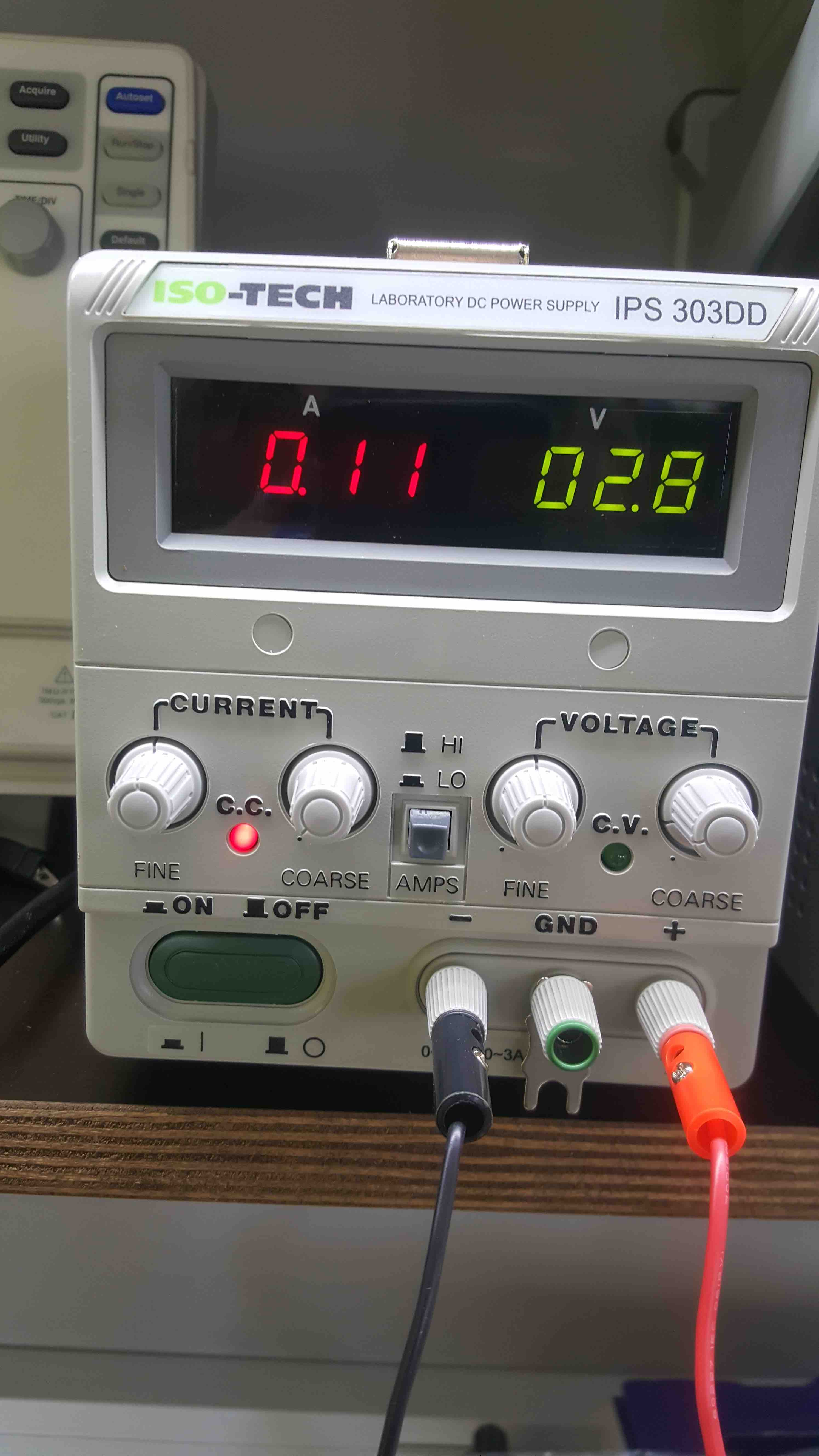
V=3 and A=0,11.. made it work...
I would need to create a mean to use them in the Fungarium to make air circulate... so
I found some students output assigments with fan
One of the main issues is the Microcontroller speed and acuracy needed to control the outputs
found inspiring page About Circuits, which I'll quote:
By default Atmega328P will work at 1 Mhz, because Fuse Bit Low default value is 0, so the value presented in Table 8-10, note 2, of 8 Mhz will be devied by 8, resulting in 1 Mhz.
Need to work on the Hardware and Software.
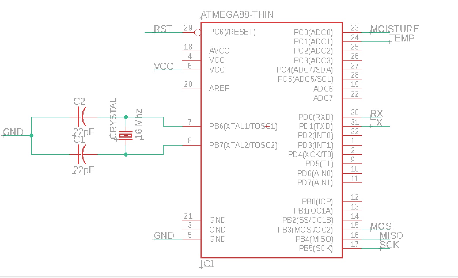
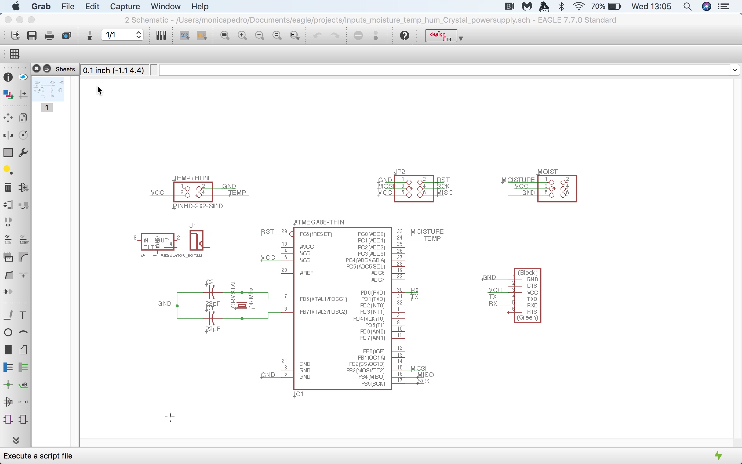
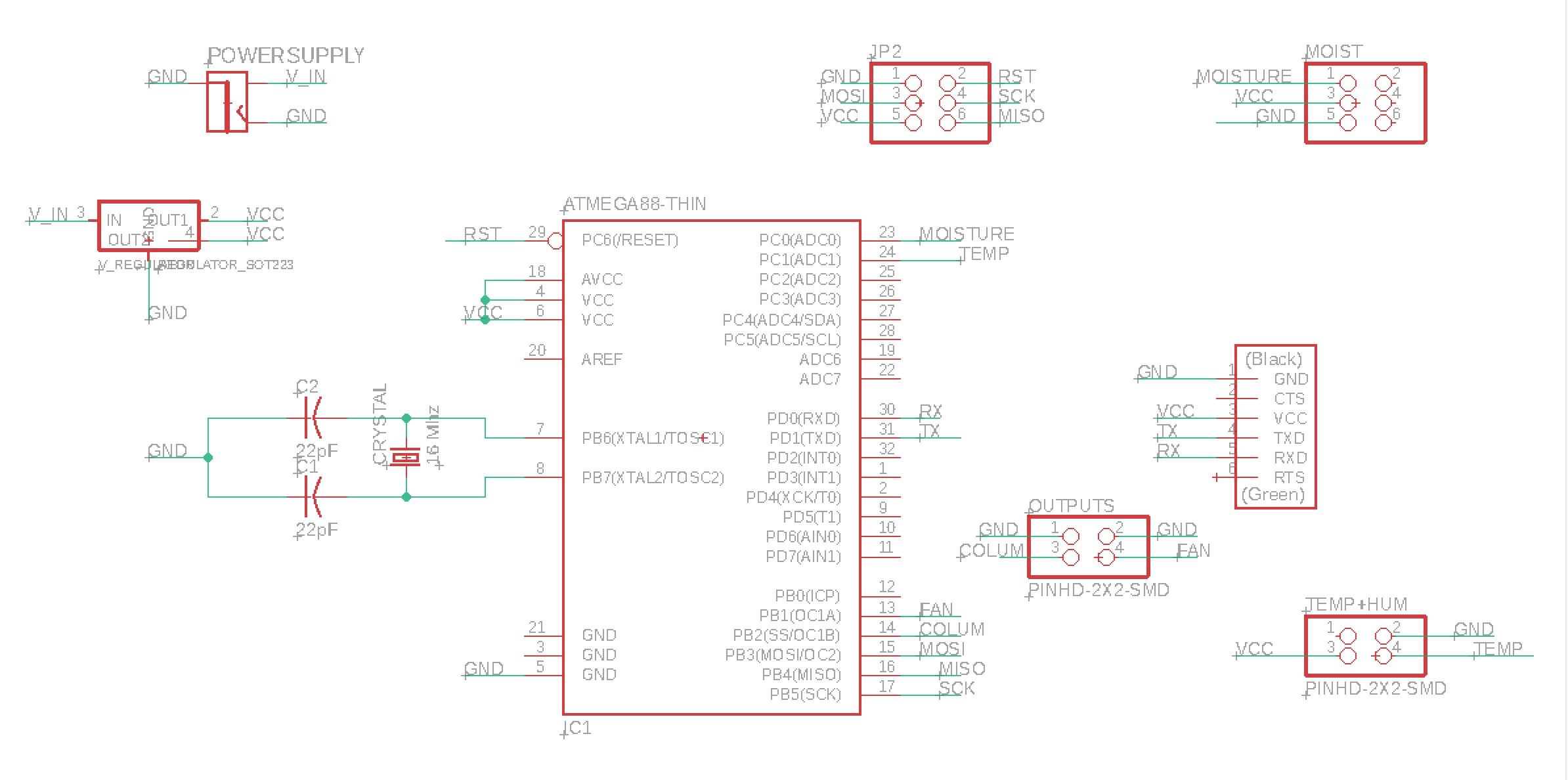
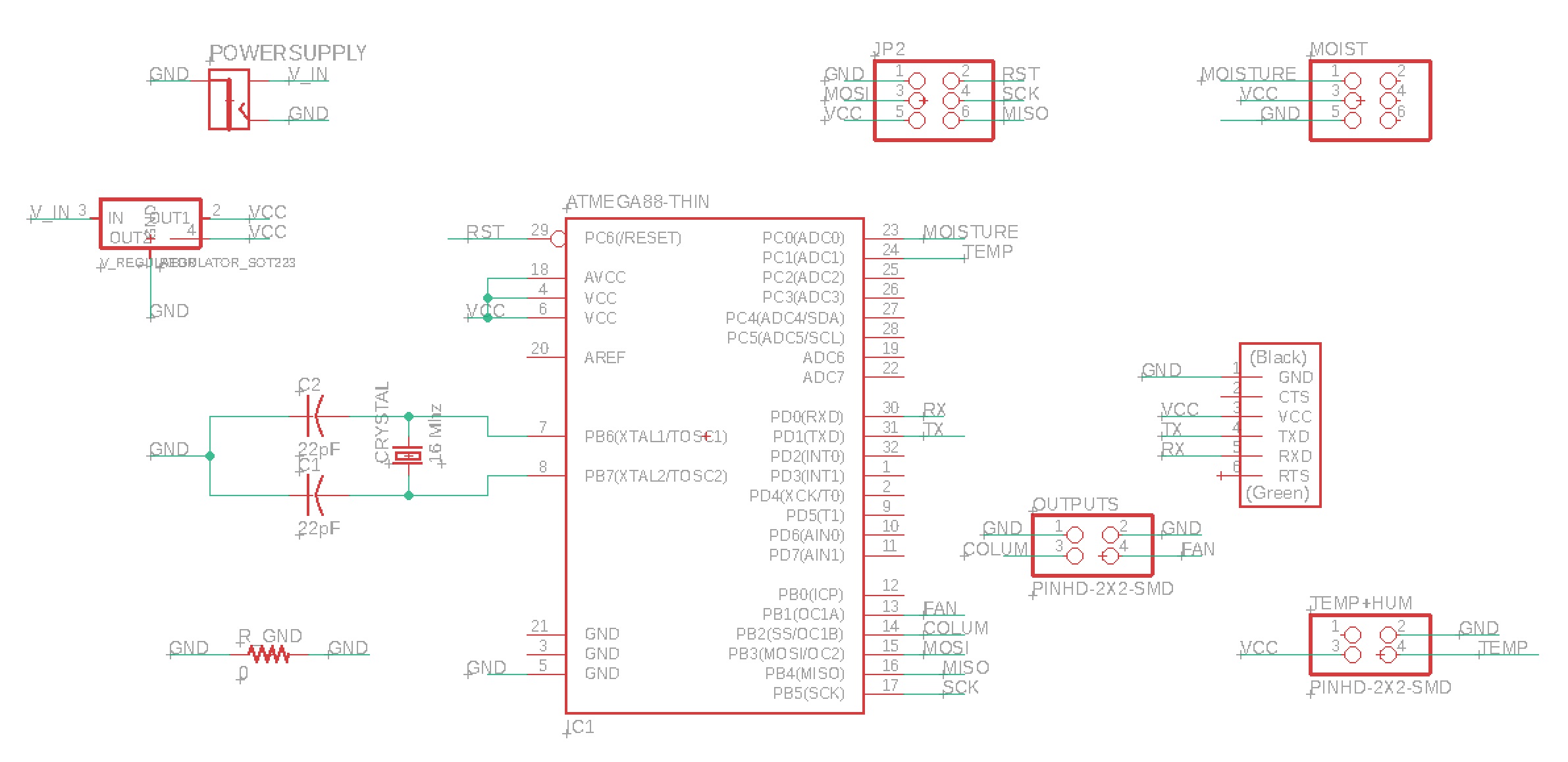
Hardware: Add a Crystal Oscillator:
            16 Mhz crystal
            two 22pF ceramic capacitors
            connected to XTAL1 as input pin
                    and XTAL2 as output pin
Here it's
Eagle 9.3.0 does not recognize FAB.LBR...
so I installed an oler version, Eagle 7.7. for MAC 64bts just to add the components, if you need here is the Zip file to install the EAGLE 7.7 MAC 64bits
Software: Change the Fuse Low Byte settings
            - only the Fuse Low Byte needs to be changed
            Considerations around the Fuse Low Byte:
                - bit 7 needs to be changed from 0 to 1
                - bit 6 can be left set to 1
                - Bits 5 and 4 control the startup time - set to 1 1
                - Bits 3-0 control the oscillator choice - 1 1 1
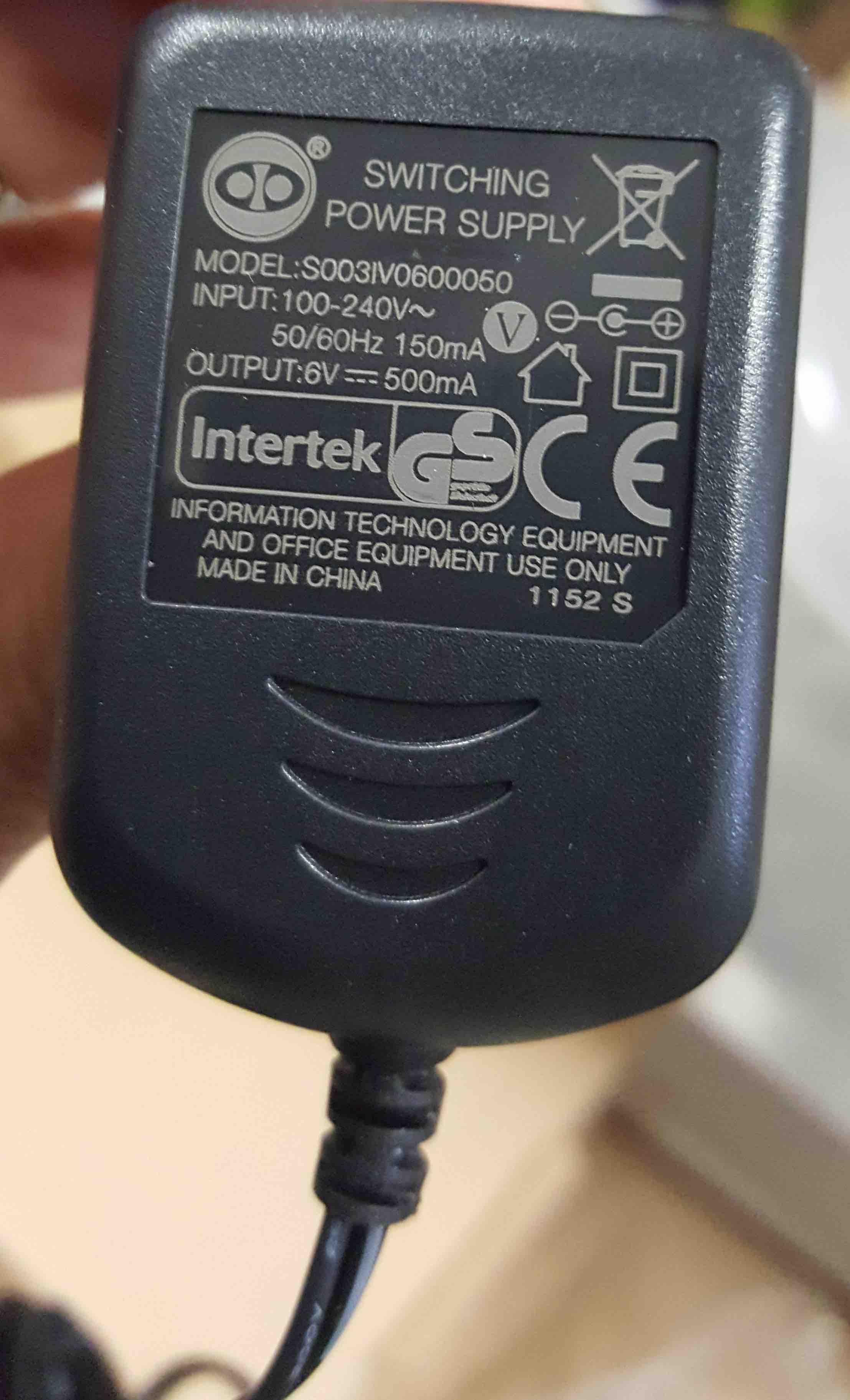
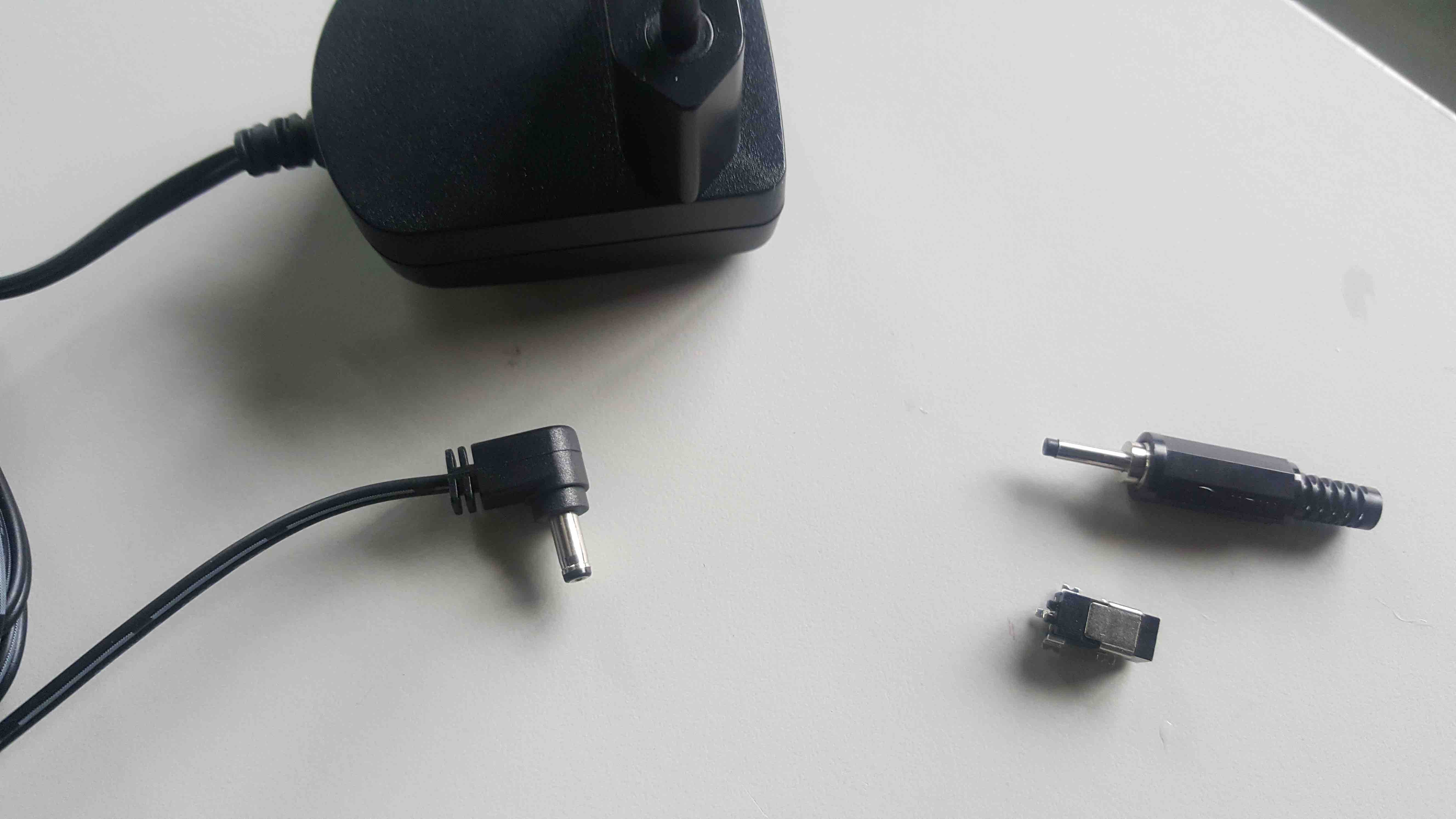
I will need to conect a external power supply, so found this one on my stuff:
adding the components in eagle 77
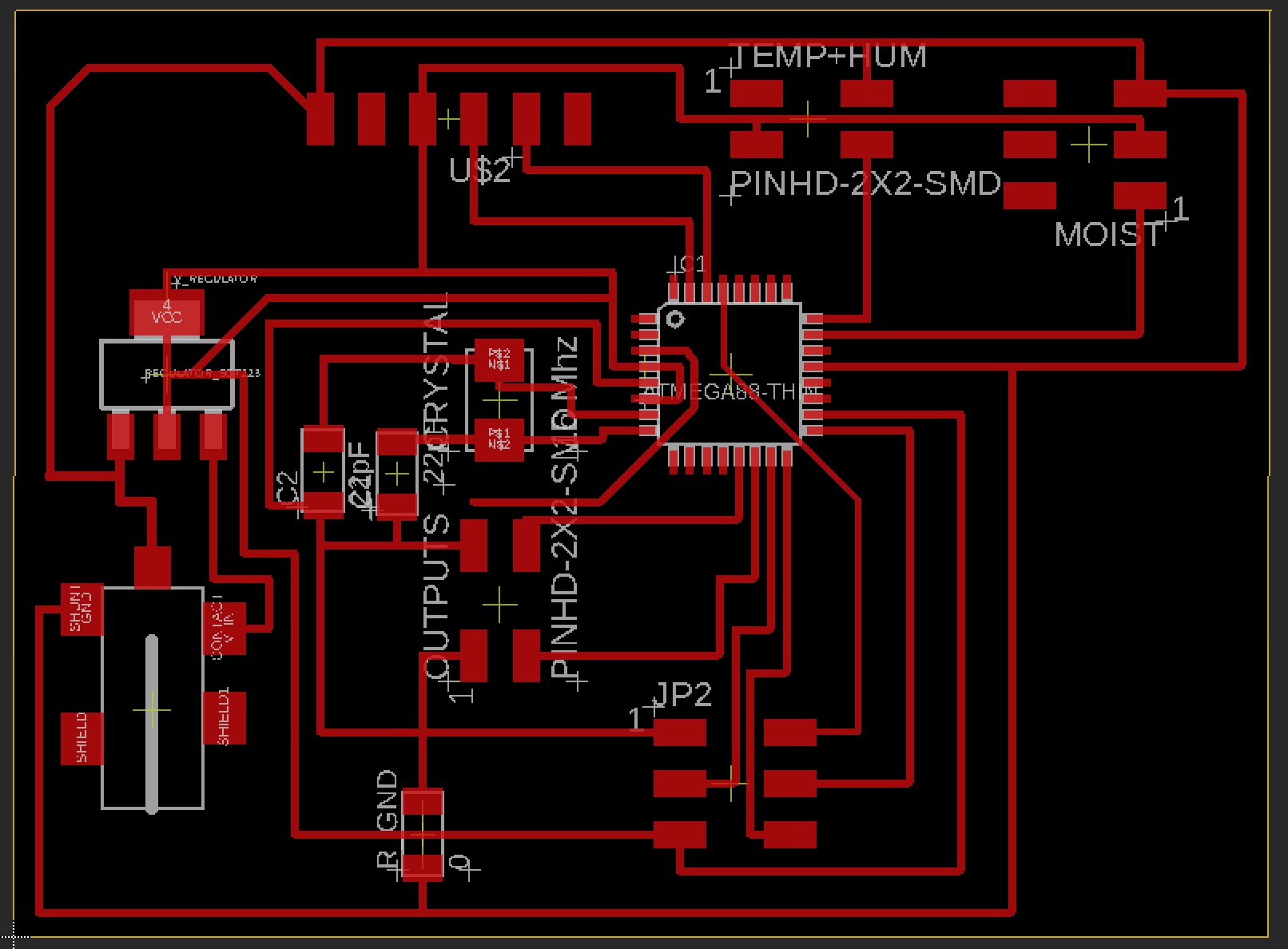
wiring in EAGLE 9.3.0
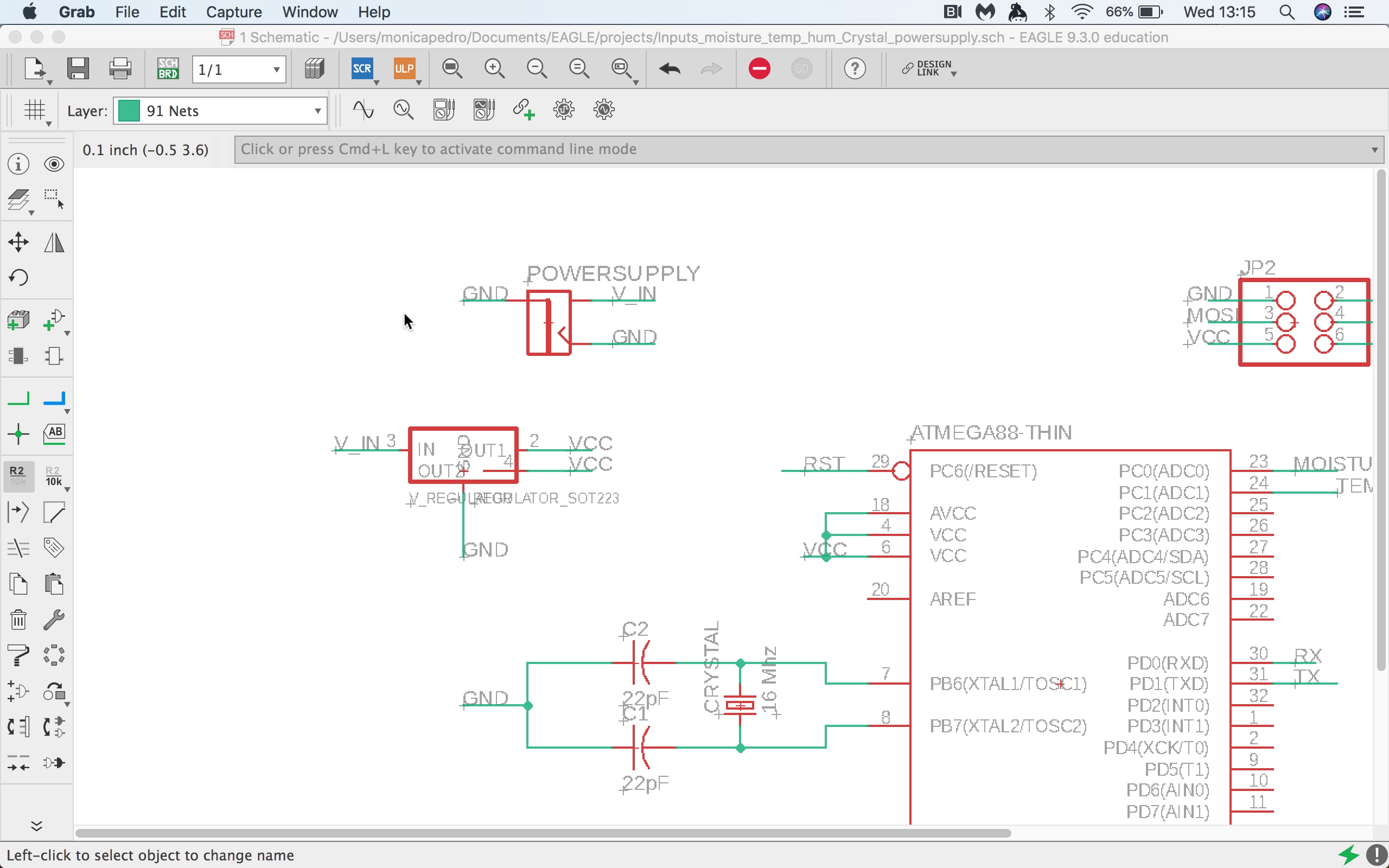
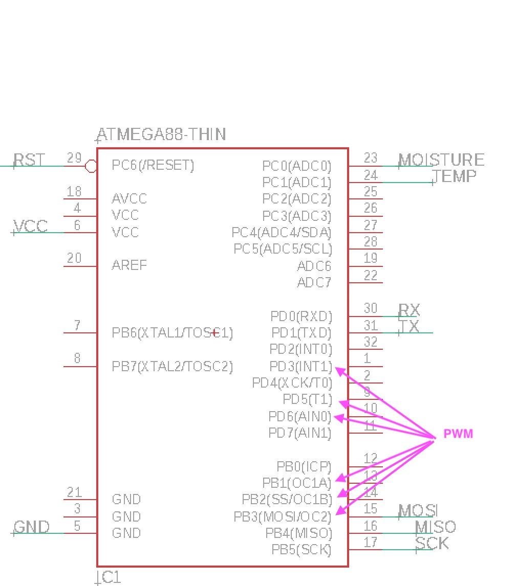
I'll connect a Pair of Colums and a pair os fans, each using 2 pin-headers
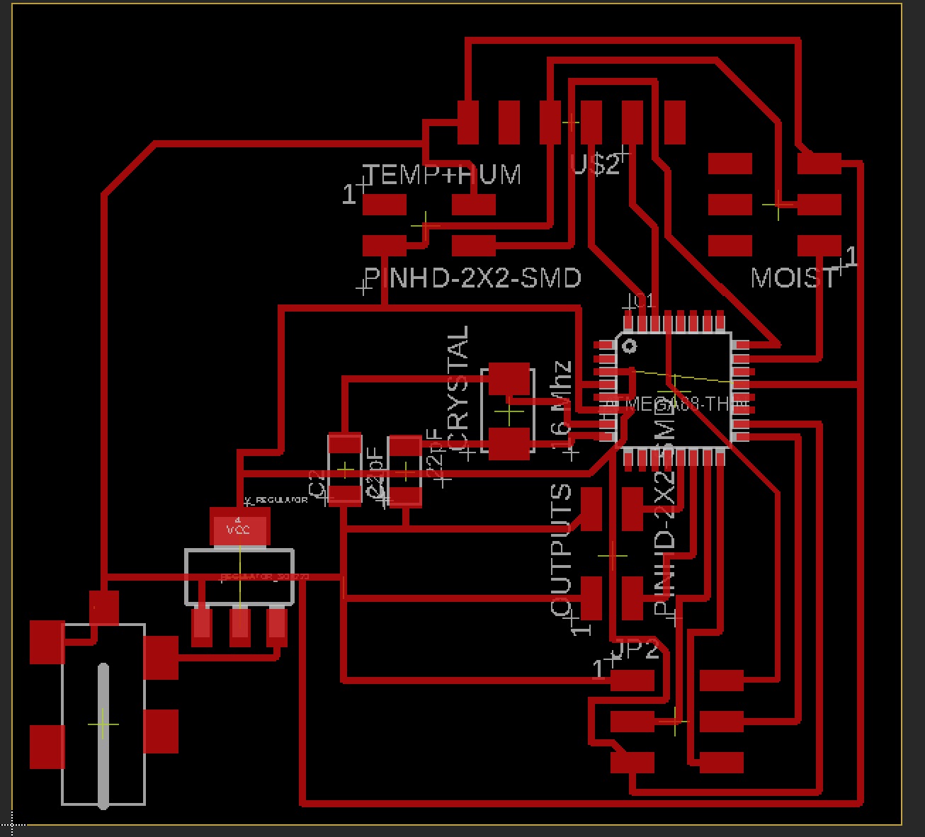
Even knowing that there's a missing link between all the GND's I'd cutted it on Milling Machine
I'm assuming a risk....that not all the Atmega328P GND pins are collectively connected.... But a read online that this could work even so....
Correction: my Fab Guro advised me to use a 0ohm resitor to connect the grounds lefting in last design... and here is the new Eagle Board Design, you can Download Schematic and Board
There was no 22pF capacitor on the lab, so I'd to join 4 to have this capacity: 10pF + 10pF + 1pF +1pF
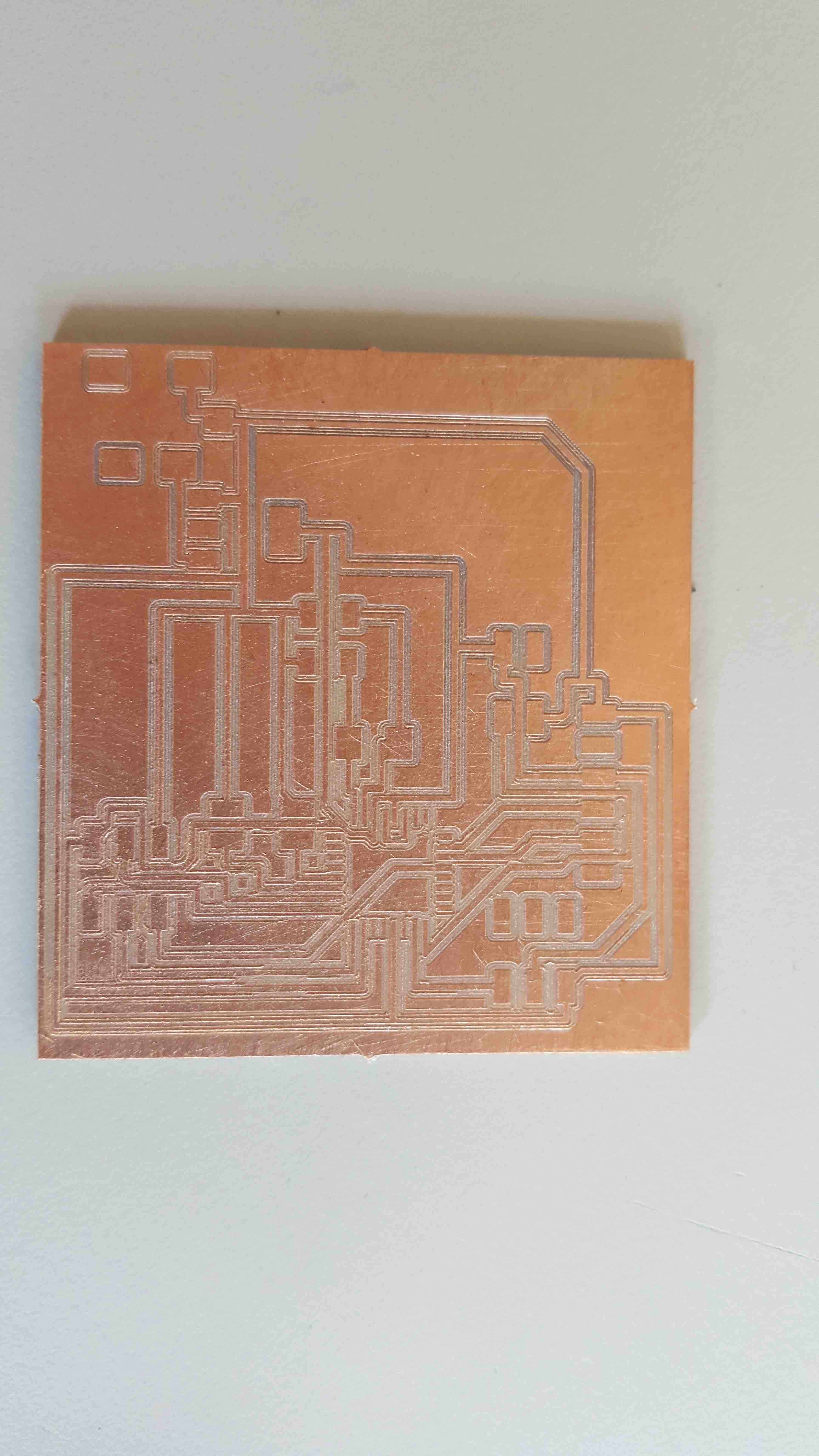
and after soldering here it is...
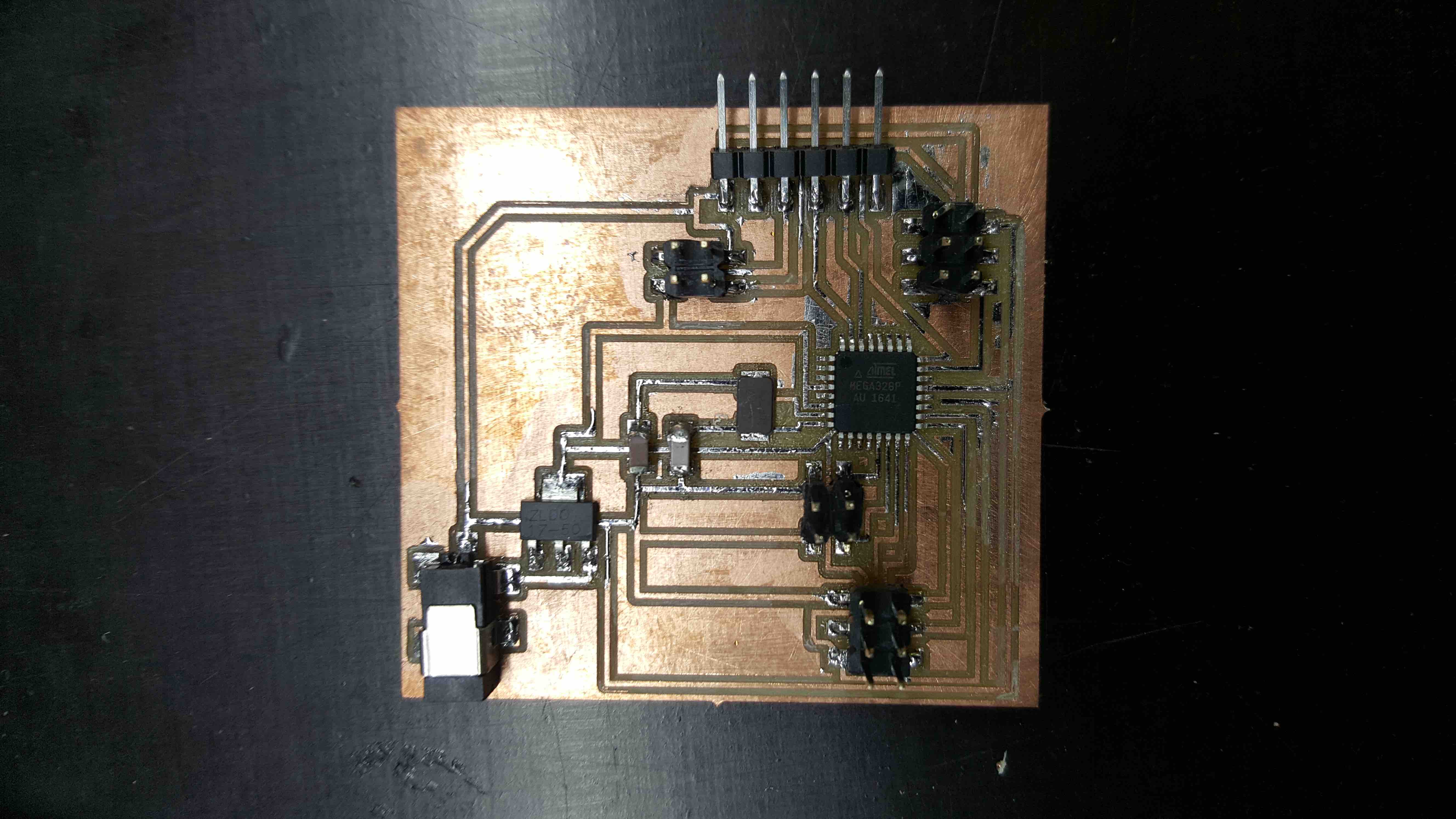
There was no 22pF capacitor on the lab, so I'd to join 4 to have this capacity: 10pF + 10pF + 1pF +1pF