Back to Mónica Pedro ←main page ←Assigments
individual assignment:
    design,
    build, and
        connect wired or wireless node(s)
            with network or bus addresses
group assignment:
    send a message between two projects
for my projet I would like to have a modular system, preferable with each sensor and actuator as a module of the whole system so that We can configure differents sets of digital monitoring for the Fungi
So I will use the previous boards designed in eagle and connect them using the I2C wire protocol
But to start working on something while I'm not able to program the two board buitl I'll play with i2C between Arduino and raspberry Pi
to try-it out onse I'll follow this tutorial from Hackers.io
But the link to the I2C.Py file was broken so I'd to find another, does one: Raspberry-Pi-sample-code/i2c.py
But the link to the I2C.Py file was broken so I'd not beem able to finishe this tutotial...
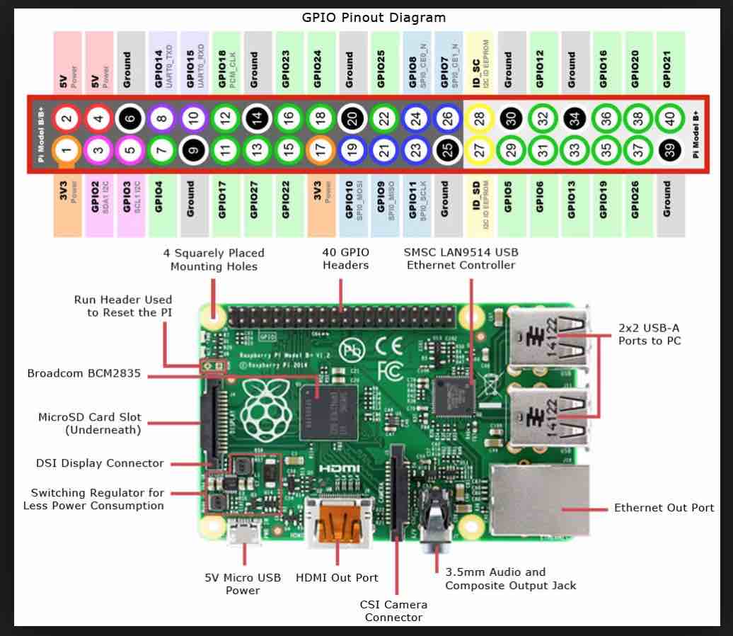
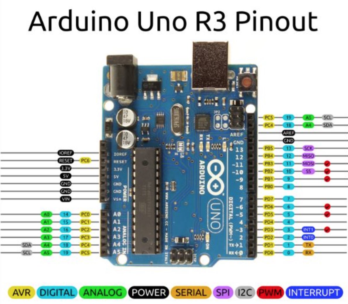
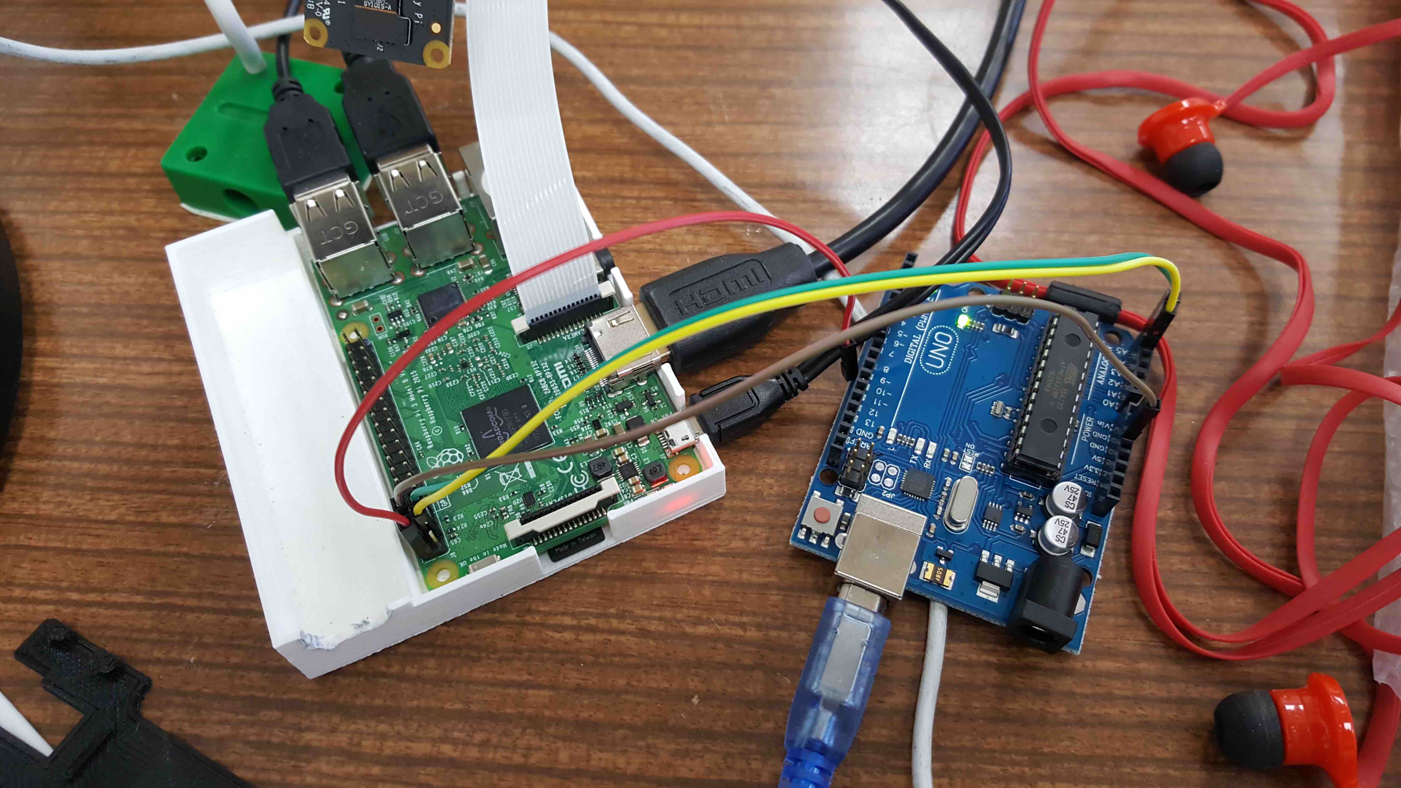
lets try another... raspberry pi and Arduino connected using i2c
Pins:
new concepts learned here:
blacklist: or blockslist is a basic access control mechanism that allows through all elements (email addresses, users, passwords, URLs, IP Addresses, domanin names, files hashes, etc), except those explicitly mentioned. Those itens on the list are denied access. The opposite is a whitelist which means only items on the list are let through whatever gate is being used....
        sudo apt-get install -y python-smbus
        sudo apt-get install -y i2c-tools
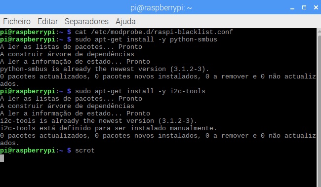
to check if the i2c is installed:
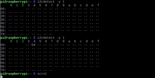
sudo i2cdetect -y 1
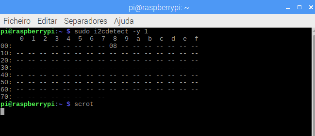
what means this i2cdected output?
        It outputs a table with the list of detected devices on the specified bus.
        Each cell in the output table will contain one of the following symbols:
        "__" the address was probed but no chip answered
        "UU" Probing was skiped, because this address is currently in use by a driver.
        "08" an addresss number in hexadecimal, e.g. "2d". A chip was found at this address...
The Arduino IDE library needed to comunicacte through i2C is the Wire.h
This library allows you to communicate with I2C / TWI devices.
There are both 7- and 8-bit versions of I2C addresses.
            7 bits identify the device, and the eighth bit determines if it's being written to or read from.
            The Wire library uses 7 bit addresses throughout.
            If you have a datasheet or sample code that uses 8 bit address, you'll want to drop the low bit (i.e. shift the value one bit to the right), yielding an address between 0 and 127.
The Wire library implementation uses a 32 byte buffer, therefore any communication should be within this limit. Exceeding bytes in a single transmission will just be dropped.
But the Microcontroller we'll use has 7-bit I2C addresses
We'll also need to communicate with the RaspberryPi via I2C
Functions:
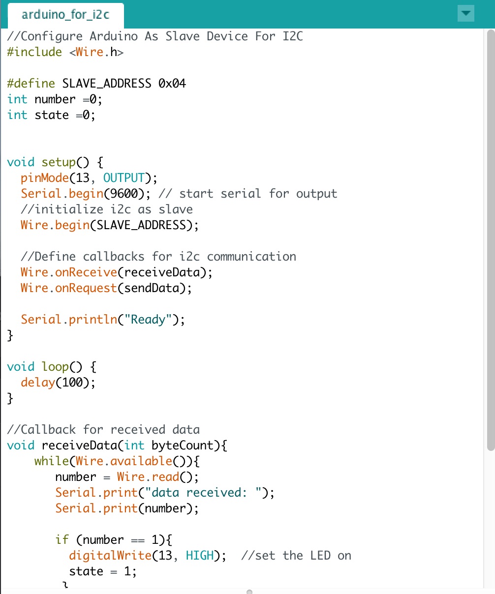 Arduino code DOWNLOAD
Uploaded the scketch and on the Raspberry looked for the IC2....
was working on this code Pyhton code not working... need to look into the provided links...
        sudo apt-get update
        sudo apt-get upgrade
        sudo apt-get dist-upgrade
        sudo apt-get install python-smbus python3-smbus python-dev python3-dev
        sudo apt-get install i2c-tools
I'd looked into many examples and had been hable to receive and divide the String comming from Arduino in RaspberryPi3
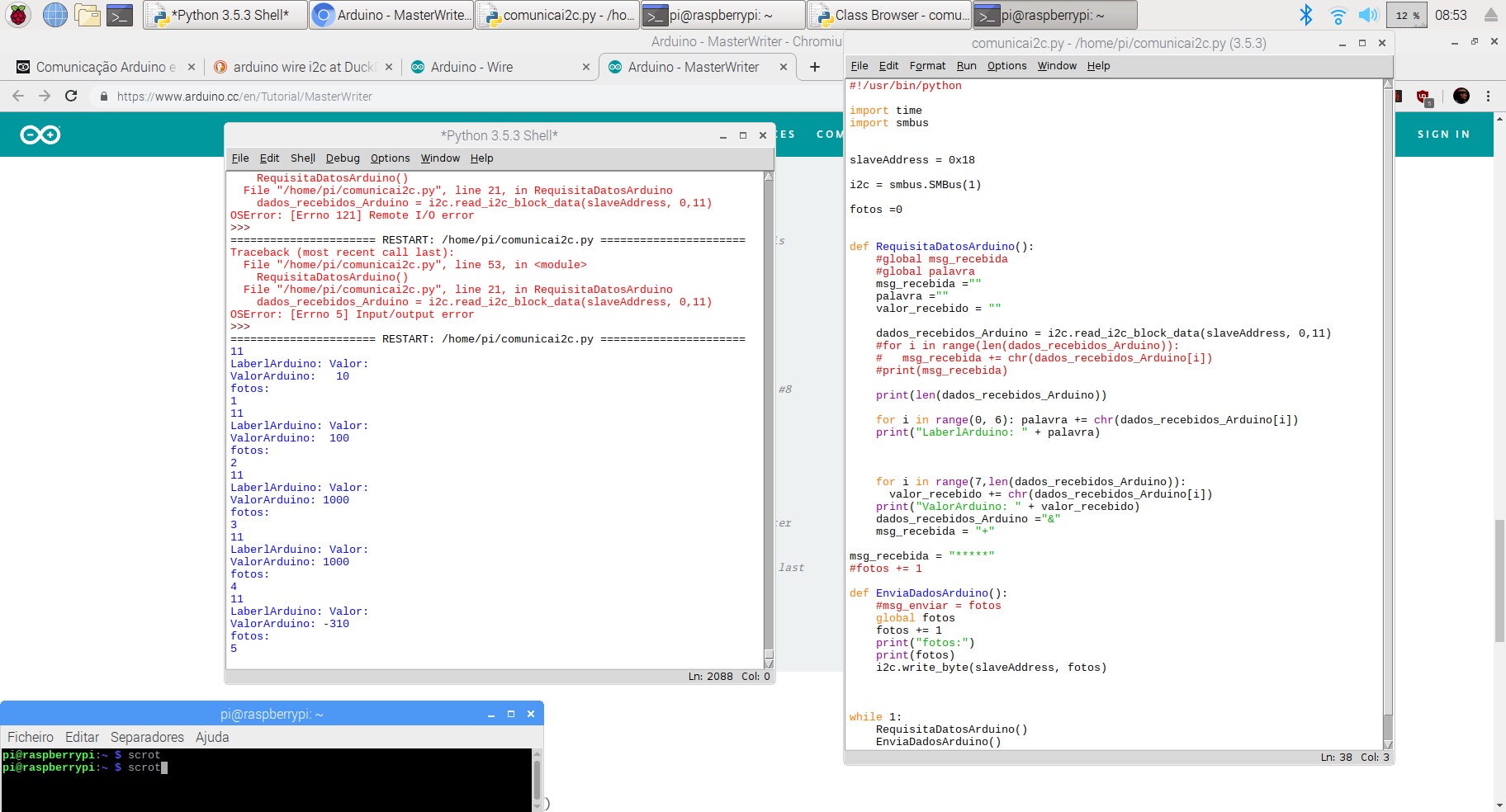
With this code the string sent by Arduino UNO is decomposed into two separate parts, namelly DataLabel and Value
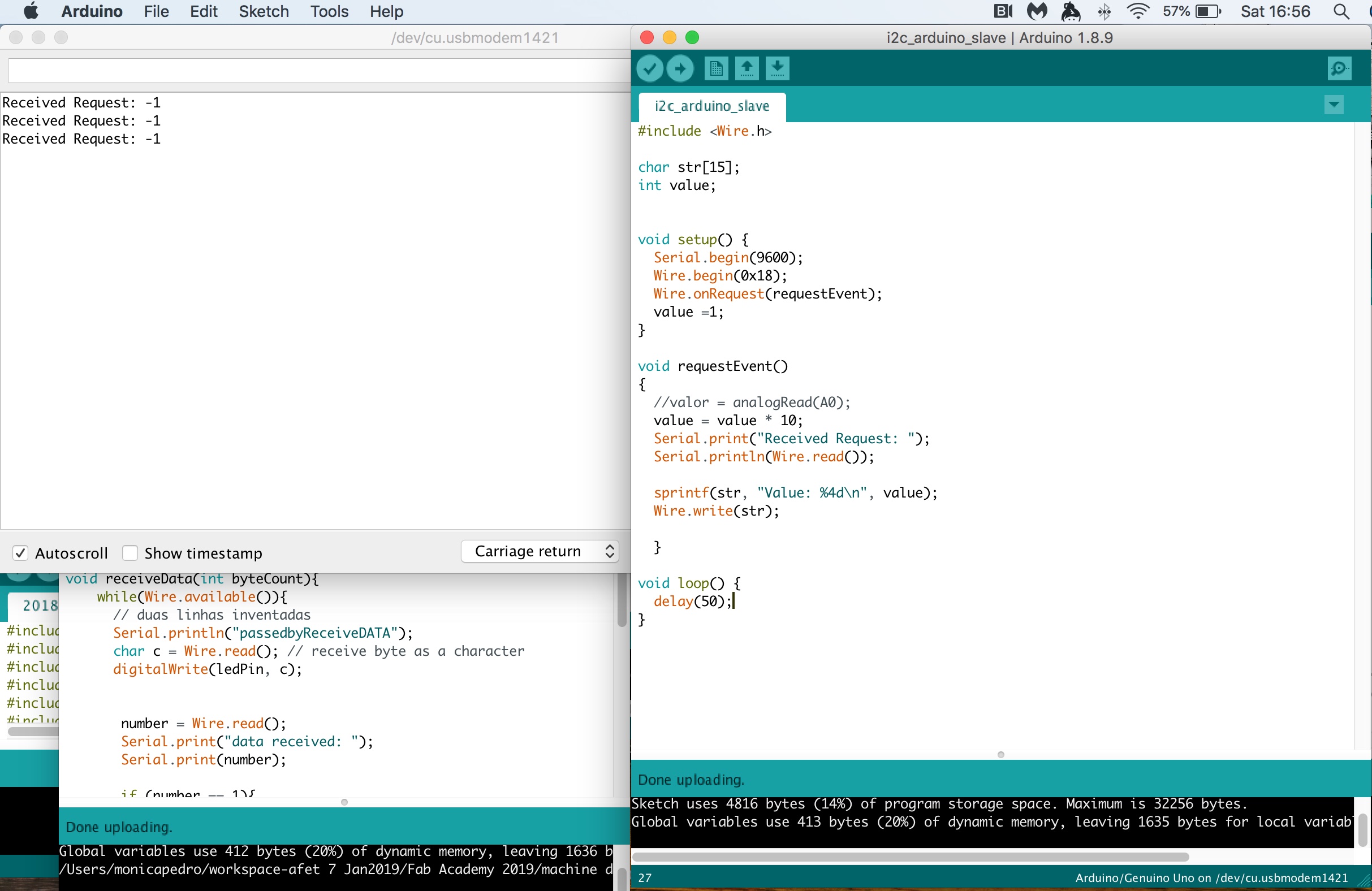
Here I'm receiving the Request, but not able to identify the value, it's not yet a meanfull value...
now the next step is to be able to send meaningful messages between the two using the byte stream
I found a quite detailed explanation of I2C with a few server's in BlueDot Tutorial
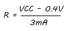
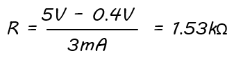
which took me to the i2C-bus specification and user manual, where it explains why we need a pull-up resistor:
        sink current accross the resistor must be less than 3mA
        maximum of 0.4V for the low-level output voltage
            so when we measure the SDA or SCL signals and voltage at logic LOW is higher than 0.4V, we know that the sink current is too high!!!!!
        The two wires, or lines are called Serial Clock (or SCL) and Serial Data (or SDA).
                The SCL line is the clock signal which synchronize the data transfer between the devices on the I2C bus and it’s generated by the master device.
                    The other line is the SDA line which carries the data.
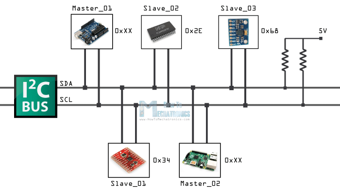
    The two lines are “open-drain” which means that pull up resistors needs to be attached to them so that the lines are high because the devices on the I2C bus are active low.
            Commonly used values for the resistors are from 2K for higher speeds at about 400 kbps, to 10K for lower speed at about 100 kbps.
We need to connect the ATmega328P Serial Clock Pin and Serial Data to corresponding SC and SD on connected parts and add the necessary pull-up resistors...
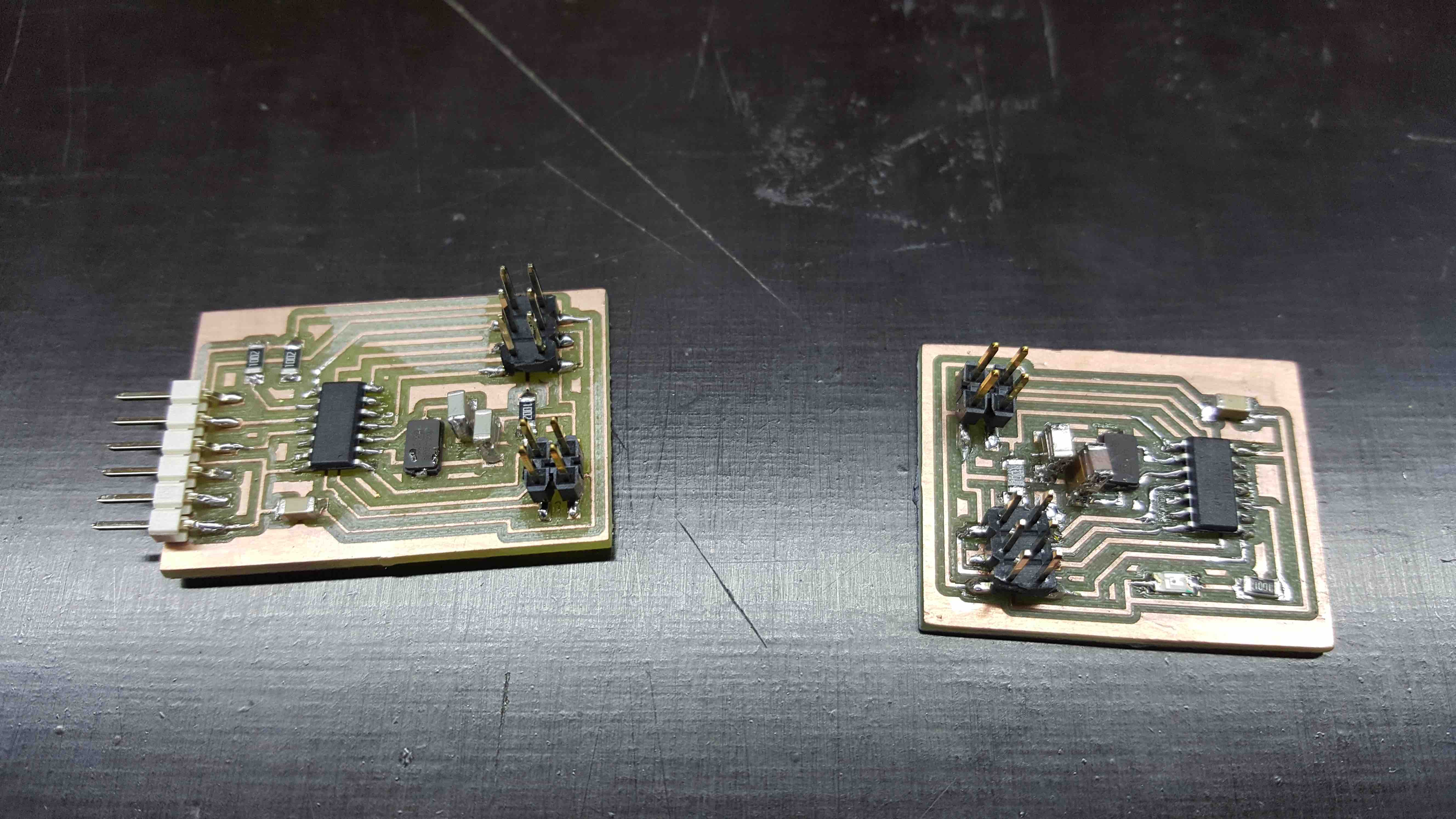
In order to learn how to deal with I2C at more accurate times, I decided to change the initial boards:
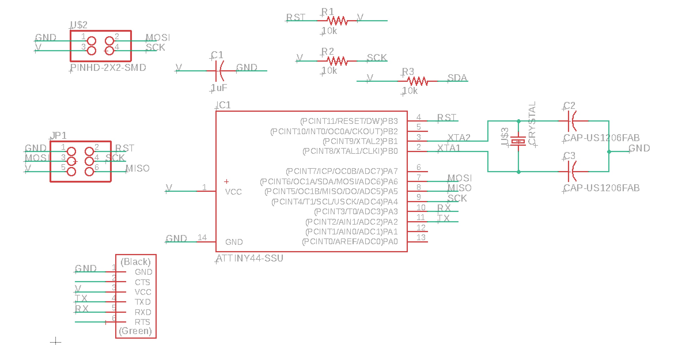
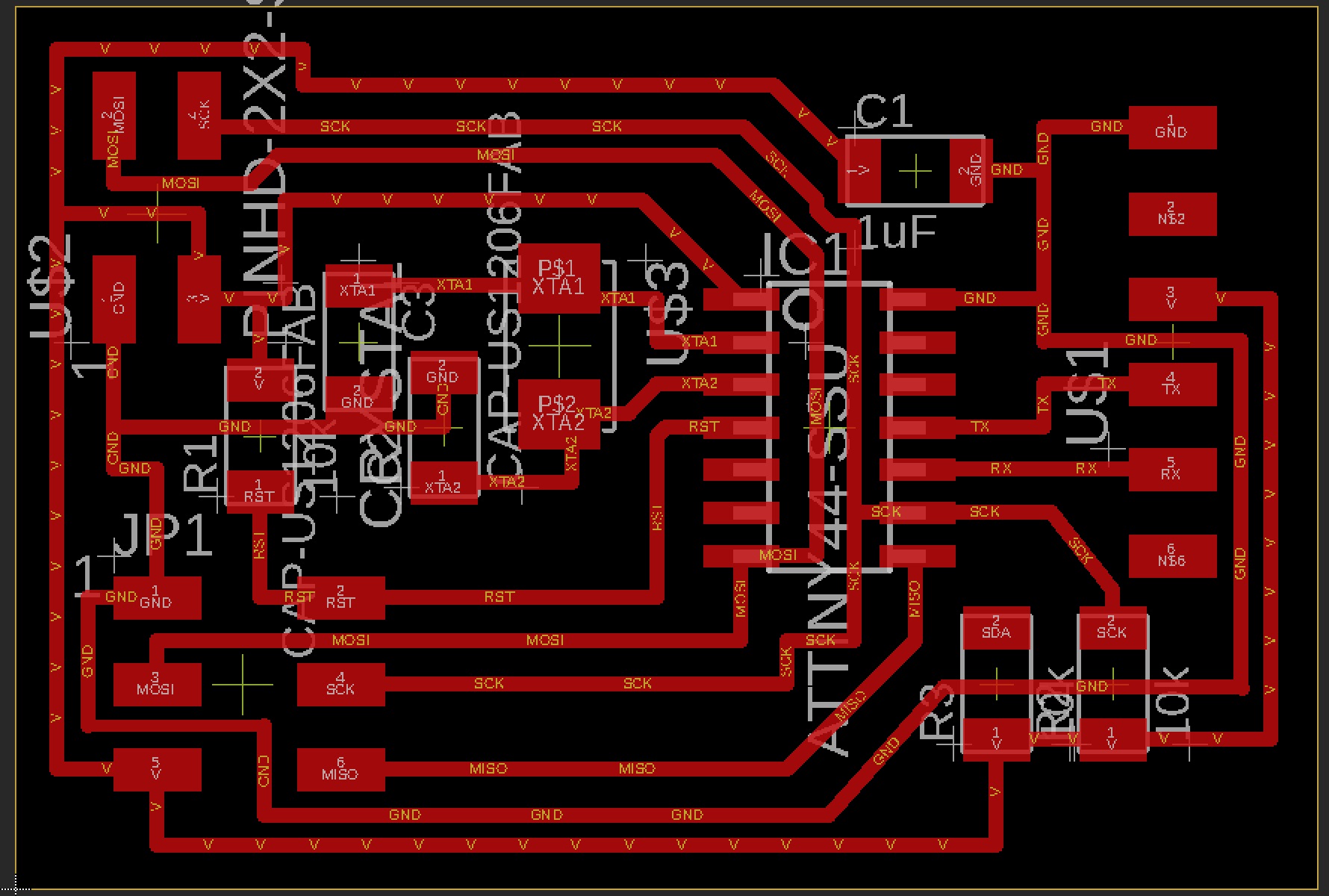
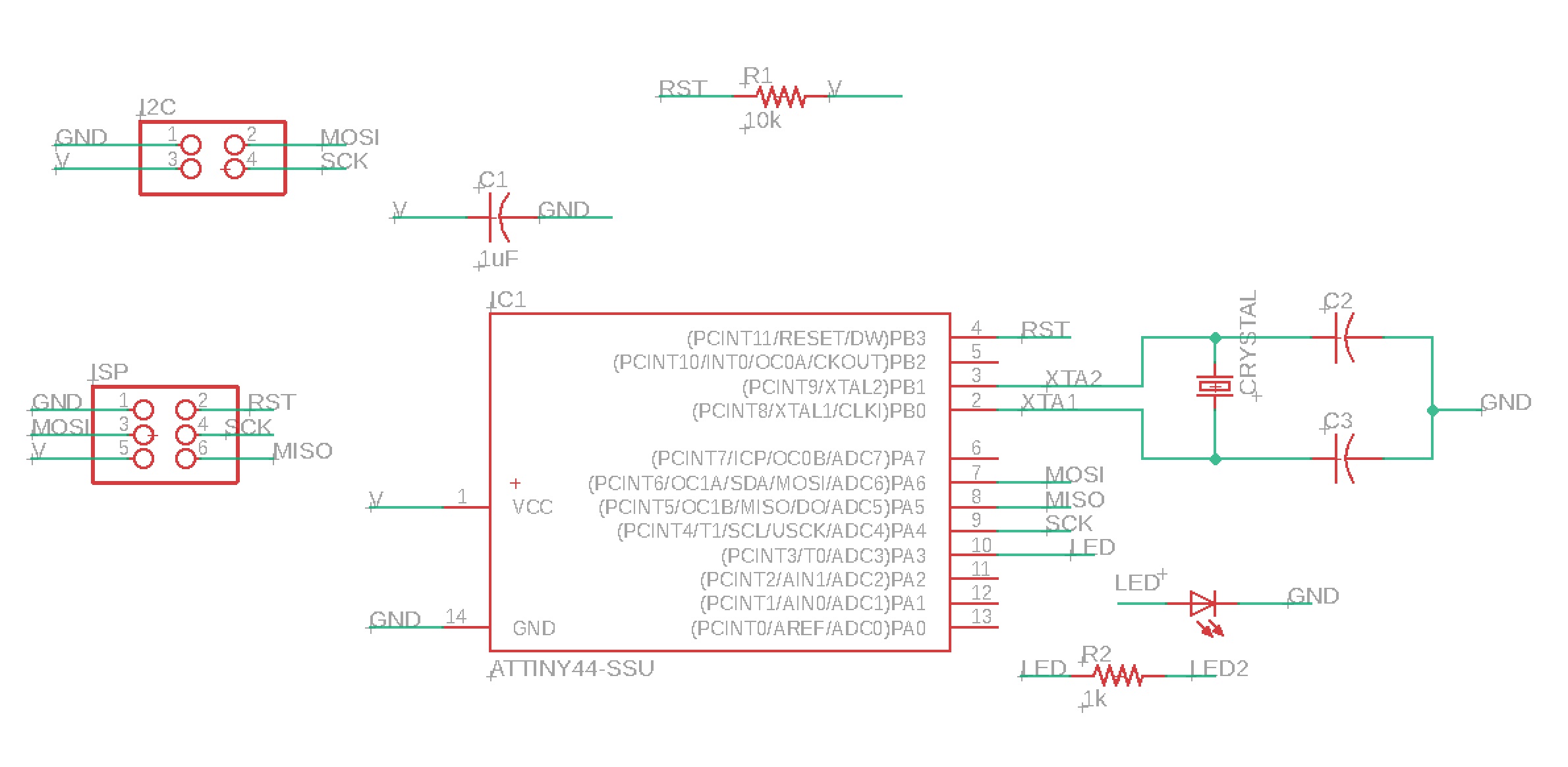

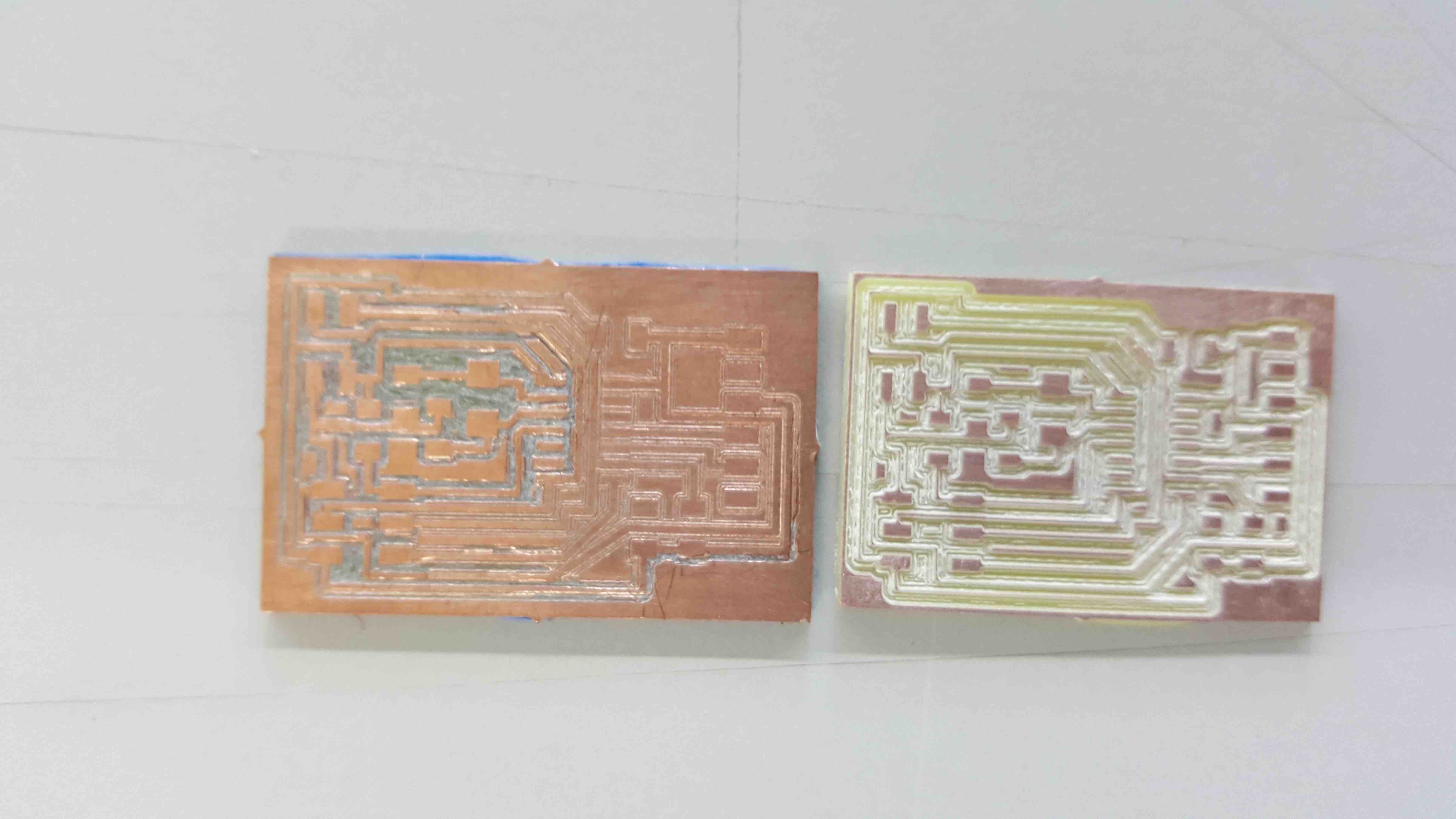
but after some fine tunning... here they are :)
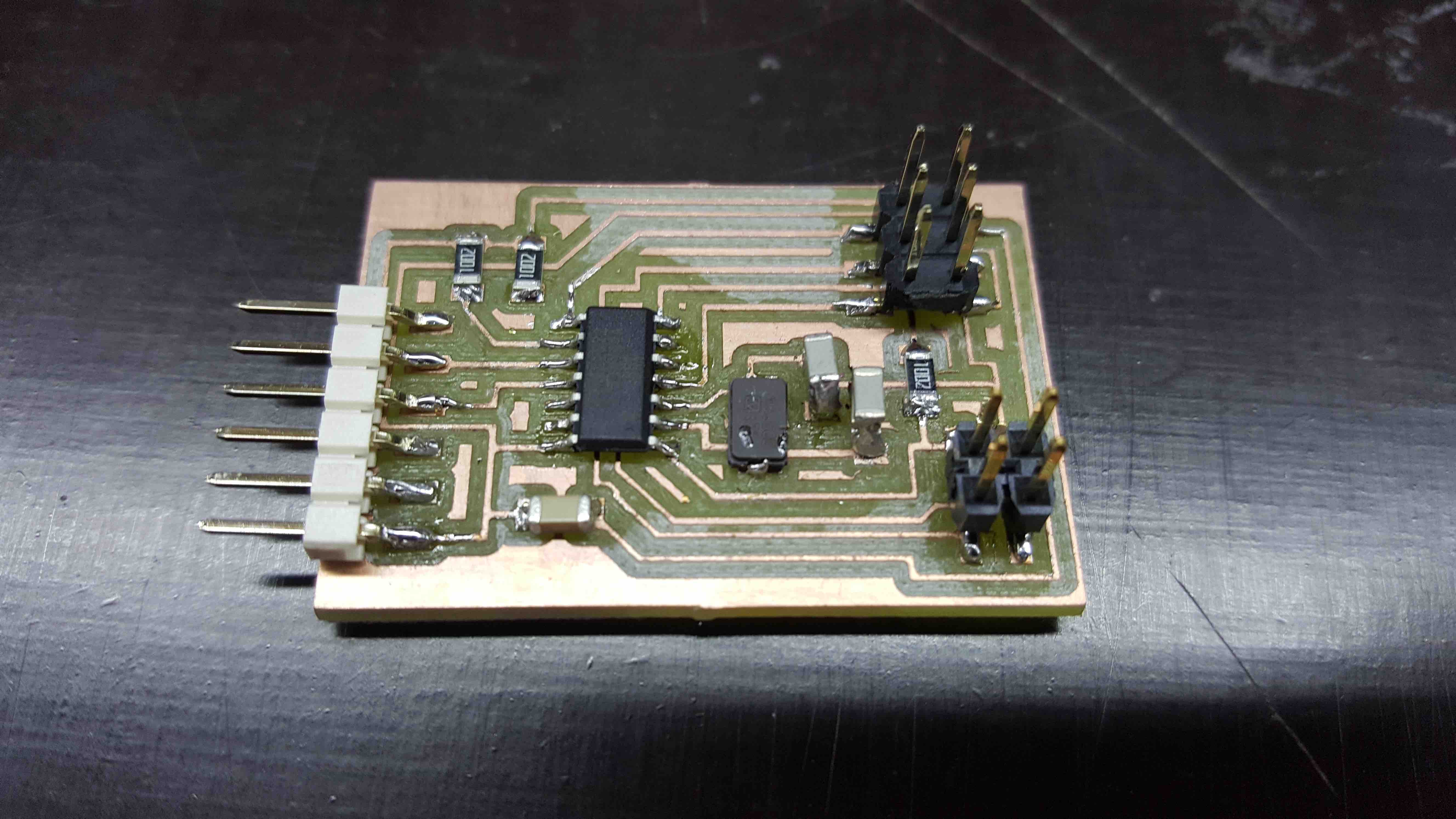
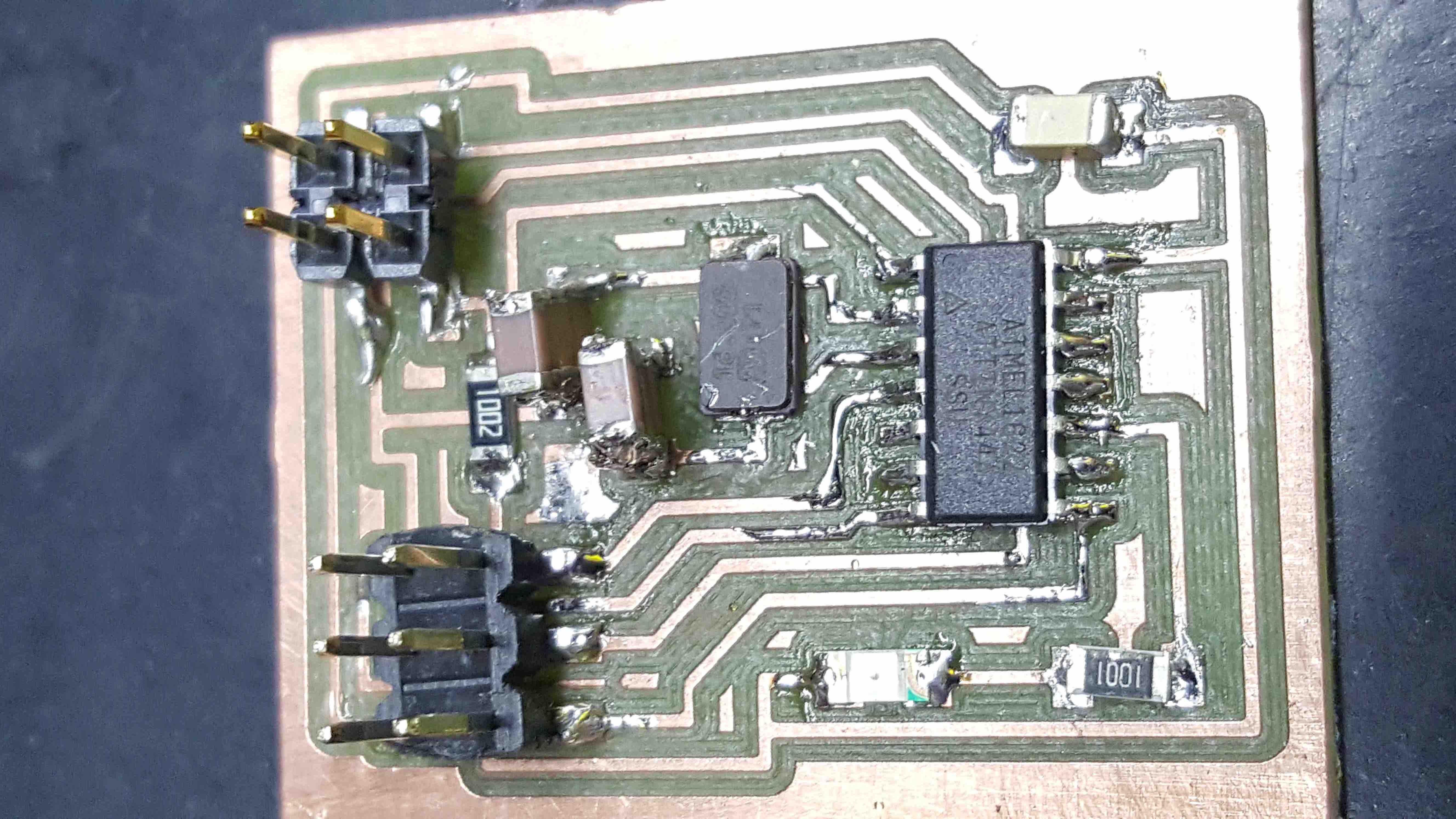
ready to be programmed....
The data signal is transfered in sequences of
     use their own 1-wire protocol for communication.
        As this protocol is based on the MASTER - SLAVE structure,
            the sensor will answer only when master requests for the data.
                Otherwise, sensor keeps quiet (remains in sleep mode).
    To access the sensor, master must follow the sequence of single bus,
        if there is a sequence of confusion,
            the sensor will not respond to the master.
        Once the sensor is powered up,
            it takes 2s to become stable.
        In this period, the sensor tests the environment temperature and humidity, and records relative data.
        When finished, it enters sleep mode automatically.
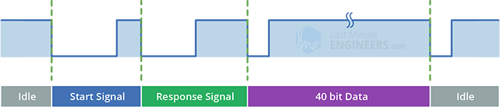
    The communication starts when the master (MCU)
            sends out a start signal.
    With this, the sensor wakes up from the sleep mode,
            switches to the High-speed mode, and
                sends a response signal.
    Following that it outputs string of 40 bits
        data consisting of relative temperture and humidity values.
    Once finished, the sensor switches back to the sleep mode automatically, waiting for the next communication.
 ←
←