#Week 08 / Computer-Controlled Machining
Research
Machines
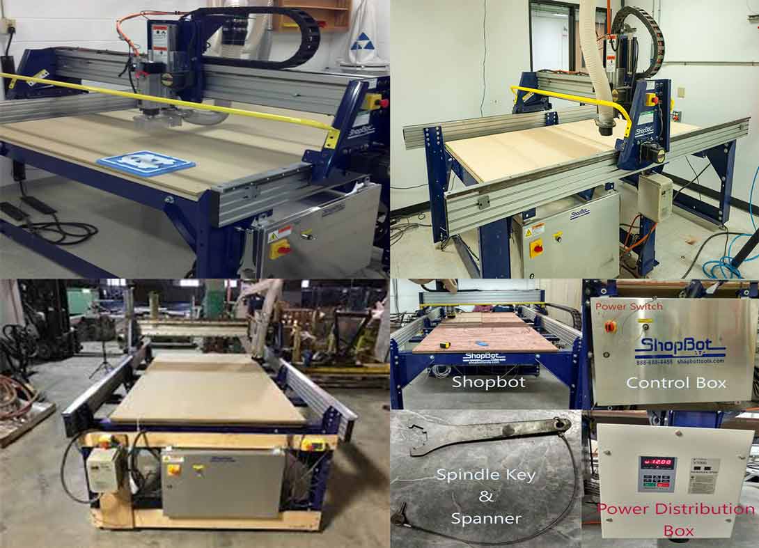
ShopBot
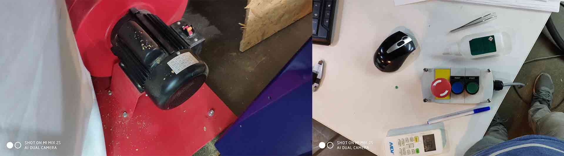
In our FabLab we use ShopBot PRSalpha 96-48 inches. Easy to configure and re-configure, learn and use, the PRSalpha CNC delivers affordable, full-production performance in digital fabrication of wood, plastic, aluminum, and other materials.
Fiatures
- Fast, closed-loop Vexta alphaStep motors fitted with low-backlash, tapered-hob gear heads on all three axes (two on the X axis) -- alphaStep system monitors motor shaft positions to maintain synchronicity between signal and motion.
- Tough precision linear bearings on the moving gantry and hardened steel rails for the x-axis.
- Reliable rack-and-pinion power transmission on each axis.
- Impressive cutting speeds of up to 600 inches per minute (depending on cutting bit and material) and rapid transit speeds of 1,800 inches per minute.
- Step resolution of .0004”.
- Positional accuracy of +/- .002”.
- Sealed Industrial UL Certified Control Box.
- Emergency Stop disconnect switch in the Control Box with integrated and cabled remote Emergency Stop Buttons.
- Z-zero Touch-Off Plate and XY Proximity Switches.
- ShopBot Control System software to run your CNC.
- Dust Skirt ready to connect to your dust collector.
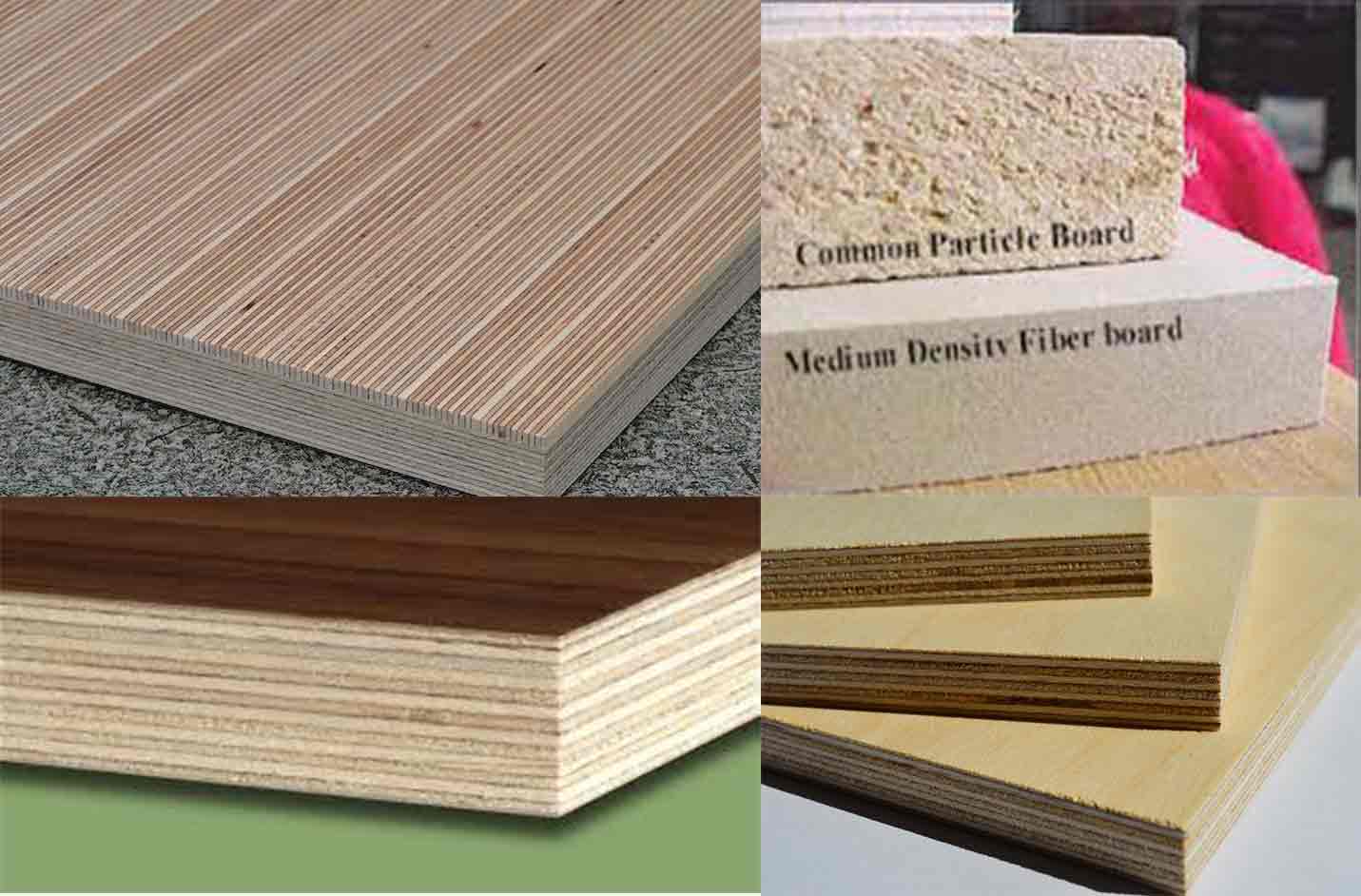
Materials
OBS
OSB may have a rough and variegated surface with the individual strips of around 2.5 cm × 15 cm (1.0 by 5.9 inches), lying unevenly across each other and comes in a variety of types and thicknesses.OSB is a material with favorable mechanical properties that make it particularly suitable for load-bearing applications in construction. It is now more popular than plywood, commanding 66% of the structural panel market.

The most common uses are as sheathing in walls, flooring, and roof decking. For exterior wall applications, panels are available with a radiant-barrier layer pre-laminated to one side; this eases installation and increases energy performance of the building envelope. OSB also sees some use in furniture production.
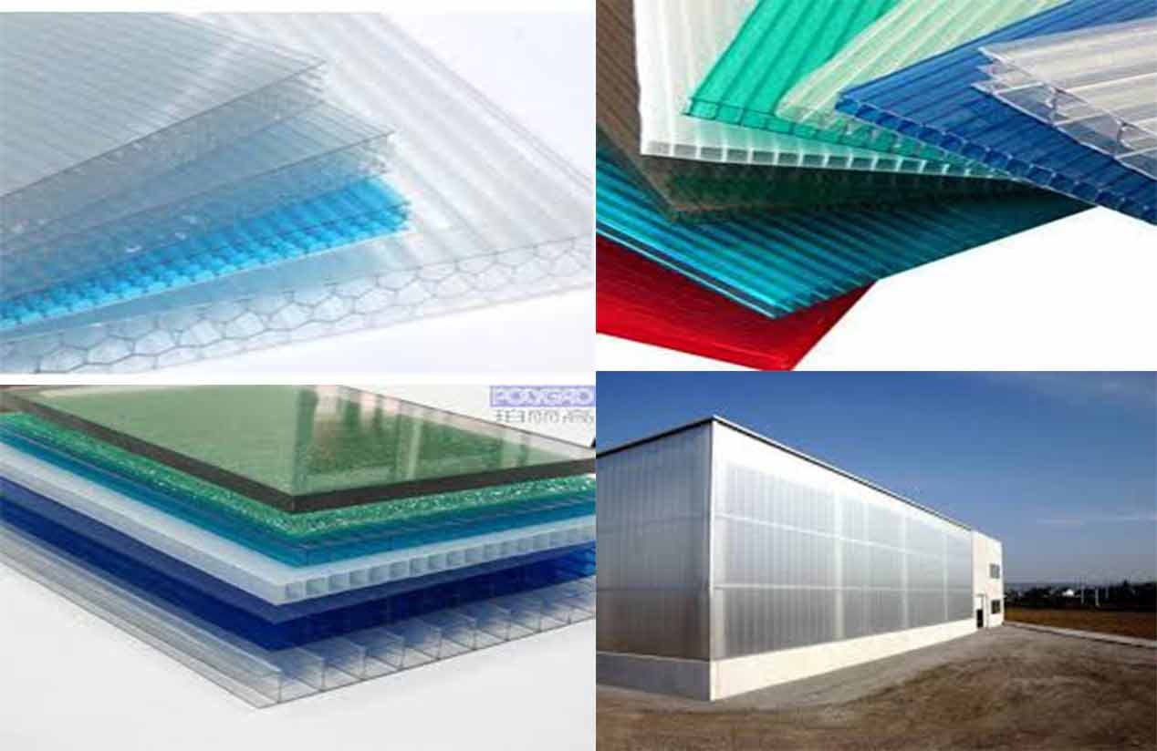
Lexan Polycarbonate
Polycarbonates (PC) are a group of thermoplastic polymers containing carbonate groups in their chemical structures. Polycarbonates used in engineering are strong, tough materials, and some grades are optically transparent. They are easily worked, molded, and thermoformed. Because of these properties, polycarbonates find many applications.
Applications
- Electronic components.
- Construction materials.
- Data storage.
- Automotive, aircraft, railway, and security components.
- Niche applications.
- Medical applications.
- Phones.
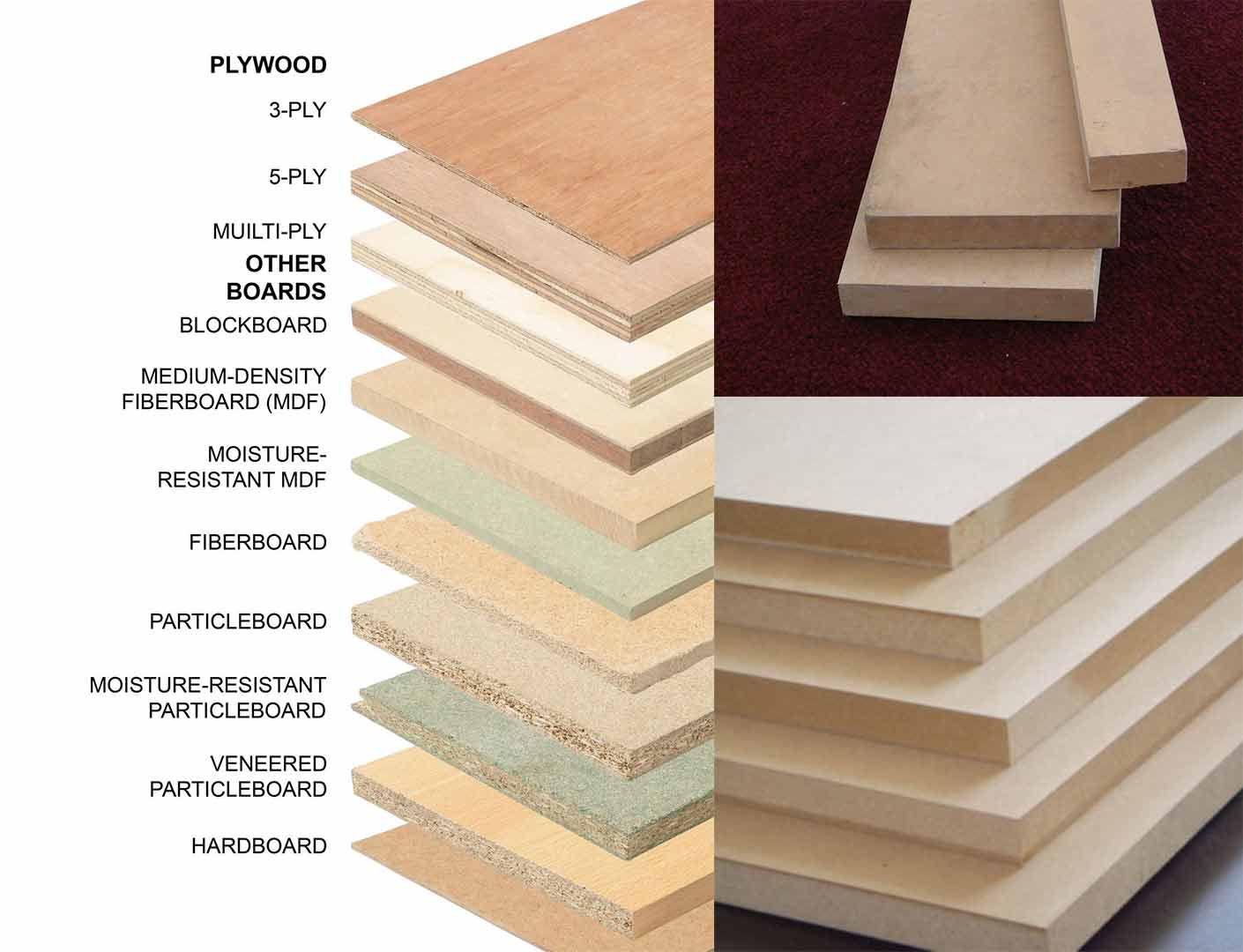
Medium-density fibreboard(MDF)
Medium-density fibreboard (MDF) is an engineered wood product made by breaking down hardwood or softwood residuals into wood fibres, often in a defibrator, combining it with wax and a resin binder, and forming panels by applying high temperature and pressure. MDF is generally denser than plywood. It is made up of separated fibres, but can be used as a building material similar in application to plywood. It is stronger and much denser than particle board.
Types
- Ultralight MDF plate (ULDF).
- Moisture resistant is typically green.
- Fire retardant MDF is typically red or blue .
Although similar manufacturing processes are used in making all types of fibreboard, MDF has a typical density of 600–800 kg/m³ or 0.022–0.029 lb/in3, in contrast to particle board (160–450 kg/m³) and to high-density fibreboard (600–1,450 kg/m³).
Veneer plywood
In woodworking, veneer refers to thin slices of wood, usually thinner than 3 mm (1/8 inch),hat typically are glued onto core panels (typically, wood, particle board or medium-density fiberboard) to produce flat panels such as doors, tops and panels for cabinets, parquet floors and parts of furniture. They are also used in marquetry. Plywood consists of three or more layers of veneer. Normally, each is glued with its grain at right angles to adjacent layers for strength.
Types
- Raw.
- Paper backed.
- Phenolic backed.
- Laid up.
- Reconstituted veneer.
Safety
When MDF or other wood sheed is cut, a large quantity of dust particles are released into the air. It's important a respirator is worn and that the material is cut in a controlled and ventilated environment. It's good practice to seal exposed edges to limit emissions from binders contained in this material.
Group assignment
Cut some part on ShopBot and test runout, alignment, speeds, feeds, and toolpaths for your machine.
Step 1)Create a sketch and cut the part.
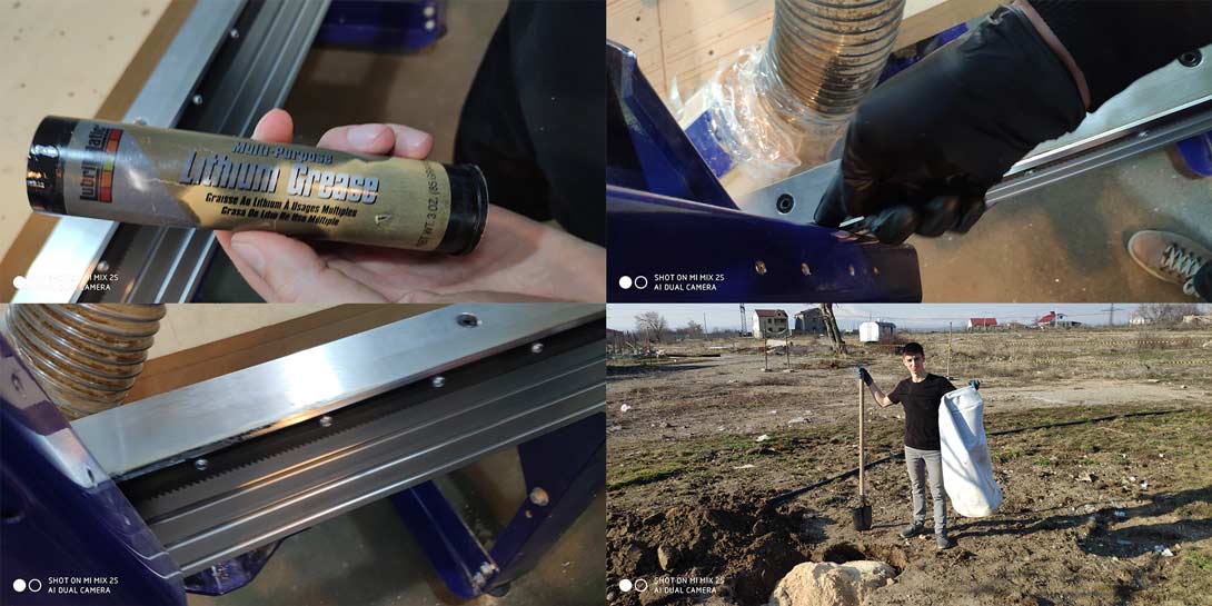
Step 1.1
Clean up and make sure you got everything to work.
Step 1.2
Sketch the part on VCarve Pro.
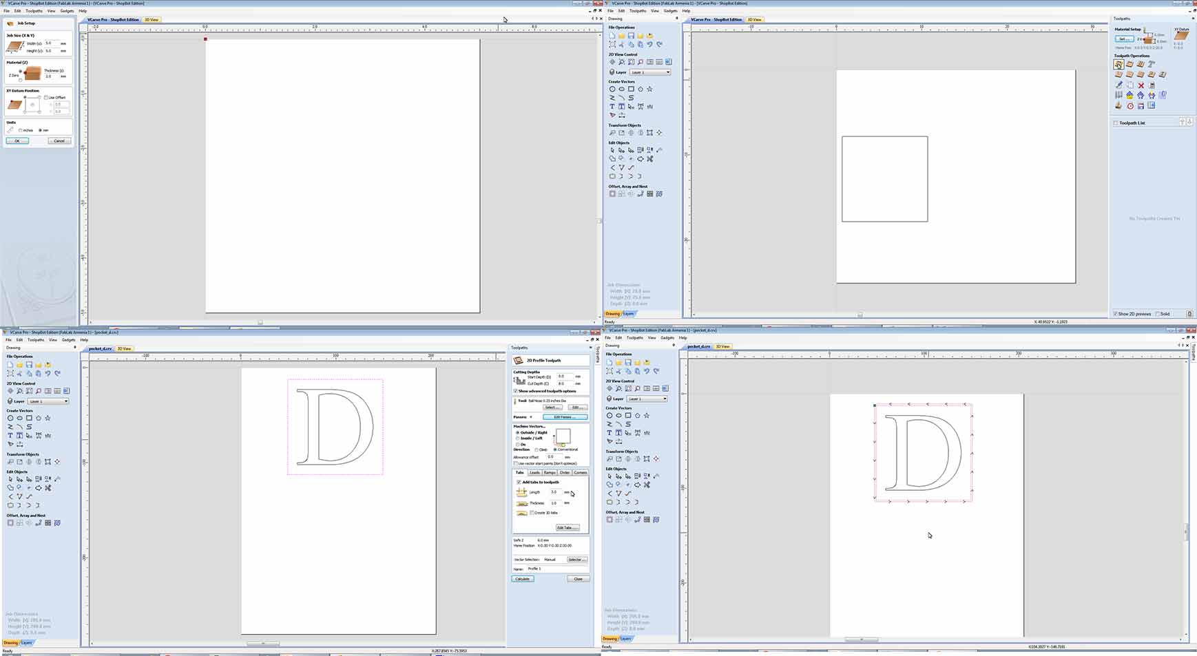
Step 1.3
Choose the tool for softwood cutting, and adjust the parameters.
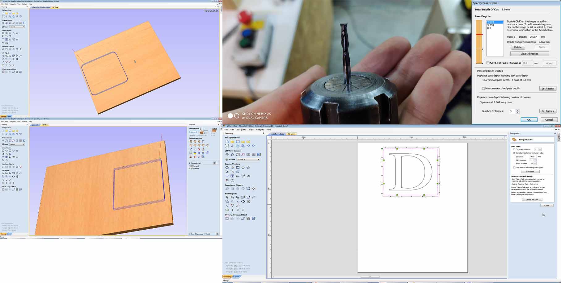
Step 1.4
After choosing toolpaths for raft and cutout Save it in ShopBot file format.
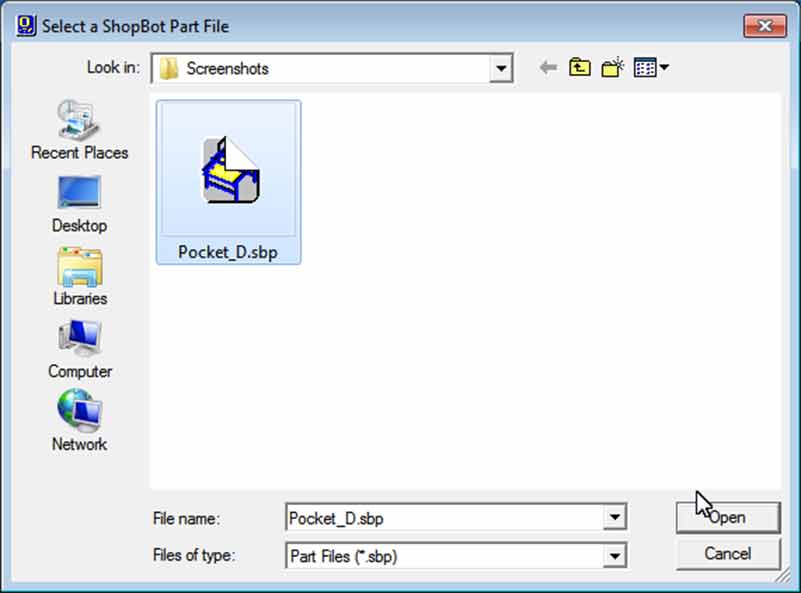
Step 1.5
After having all files you must fit the material on shopbot surface and 0 the axis(X ,Y ,Z) of ShopBot .Just Simply go to at the position where you what to 0 X, Y and 0 it, for the Z axis you can use z zero plate.
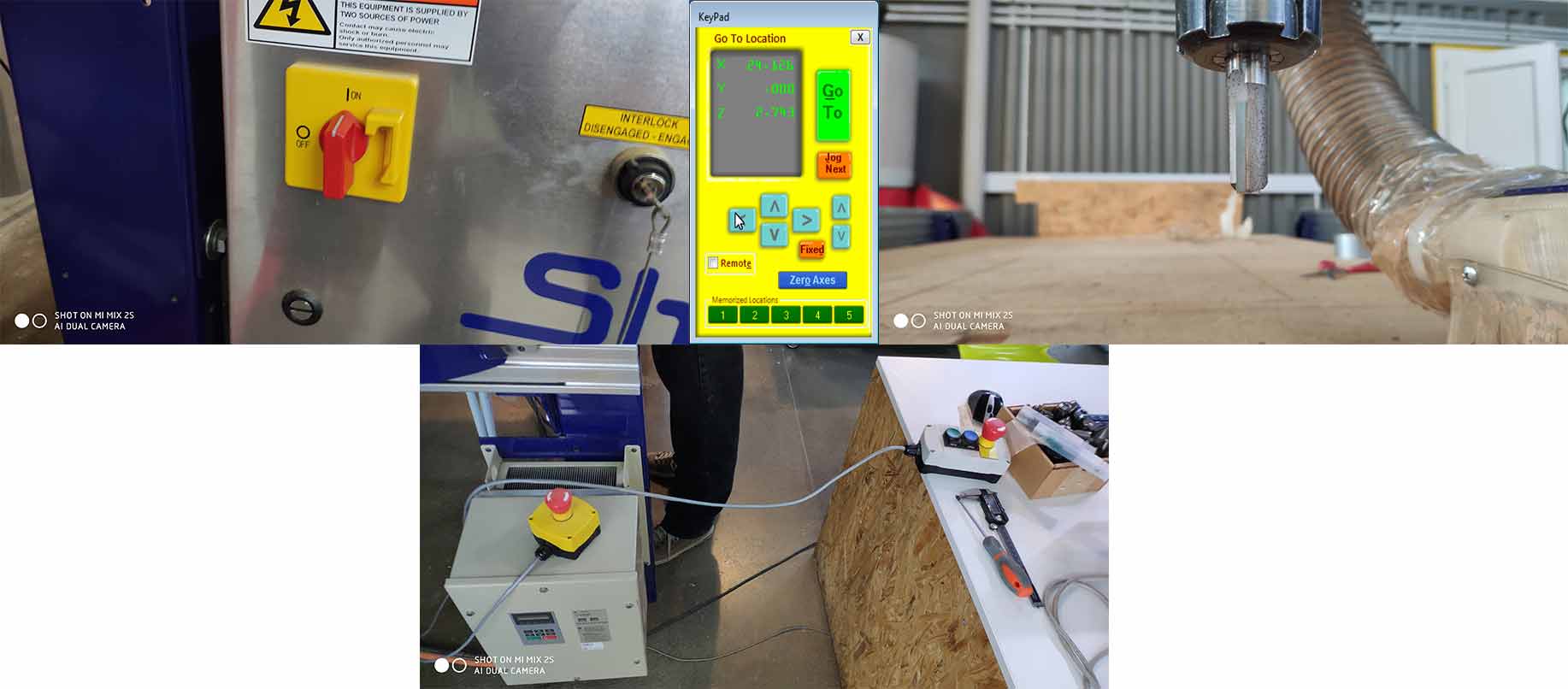
Step 1.6
After 0 all axis and having all files, you can cut by pressing Cut Part(make sure your tool is near to zeroed axis) Press Start button on the remote controller and it will start cutting (Make sure your dust collector is turned on before starting cutting).
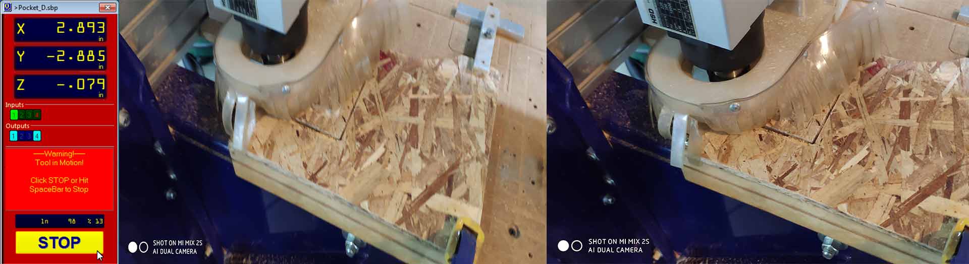
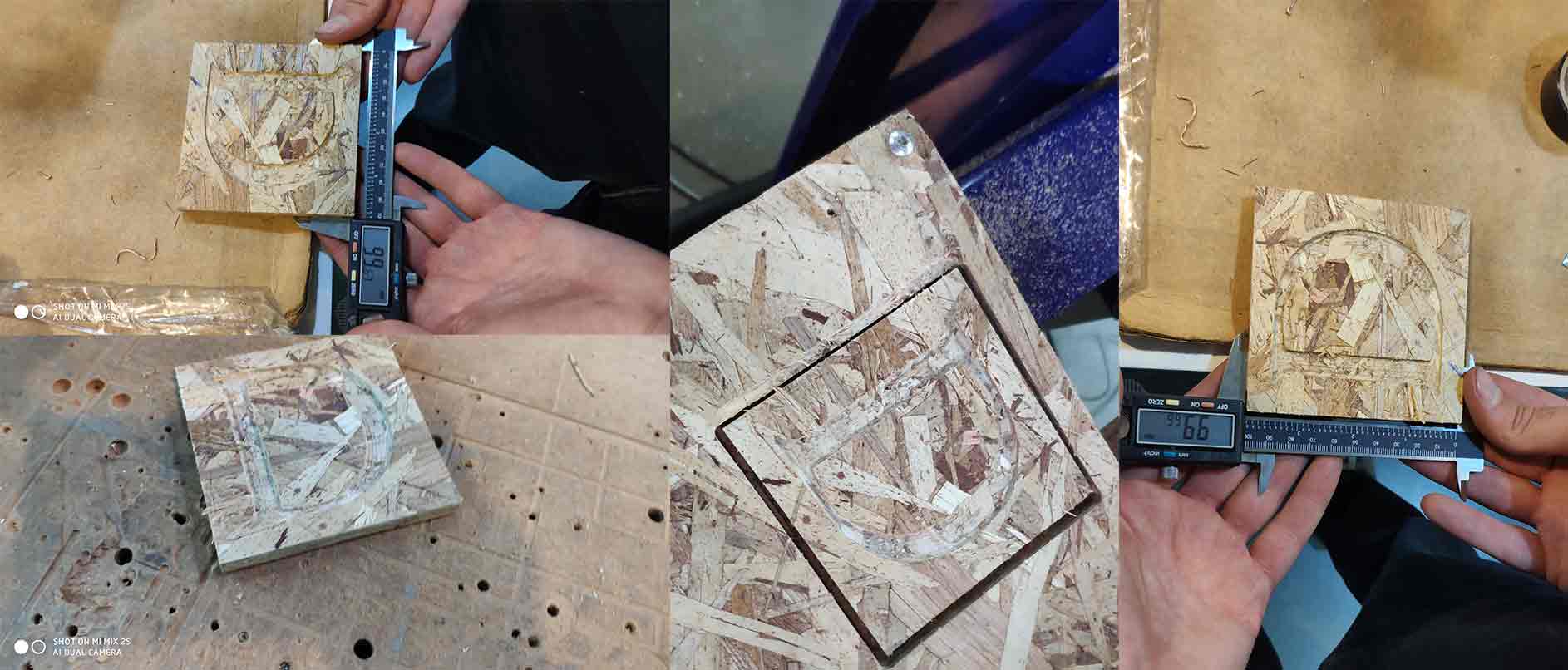
Step 1.7
After its finish remove the material (make sure that key is turned clockwise ), and measure it.
More About Dogbones
fusion 360 dogbone script, cnc box joints, dog bone joint, cnc joinery, cnc sharp inside corners, cnc router inside corners, cnc router box maker, undercut, mickey mouse ears, tbones, t-bones
When cutting materials with the CNC, a known problem is that while the CNC can make a perfect outer corner, the inner corners can never be more sharp than the diameter of the cutting tool. So if you are e.g. using a 6mm mill, all the inside corners will not be perfect right angles, but will instead have an inside diameter of 3 mm (half the cutting tool's diameter) Sometimes these small rounded corners don't matter, but they are almost always an issue with joints - where often another piece of plywood, which by nature is square, must fit precisely in a hole or slot. If the hole or slot has very rounded corners, the mating piece just isn't going to fit in.
Individual assignment
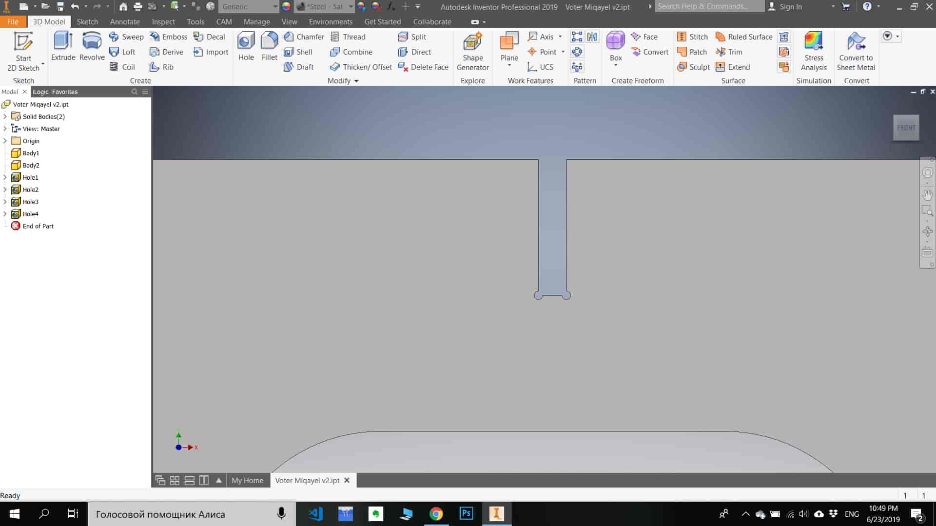
Step 1)Object modeling .
Step 1.1) Skech 3D model .
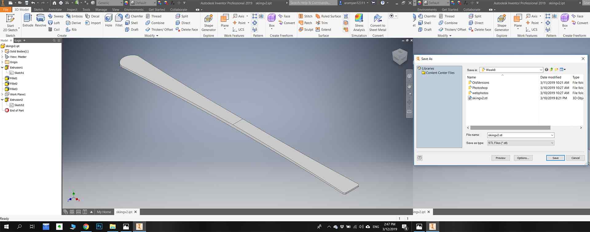
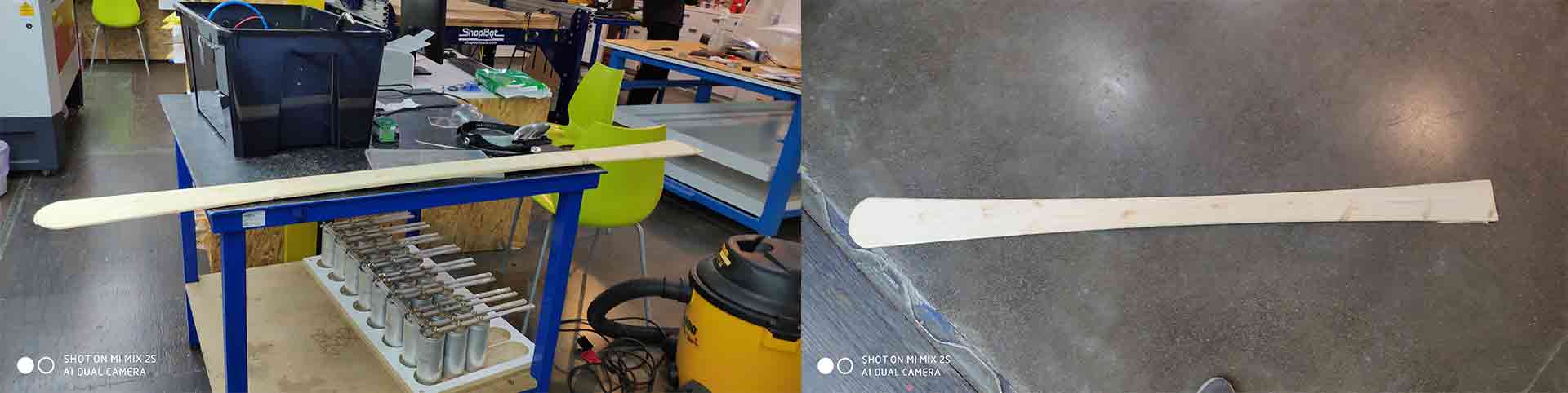
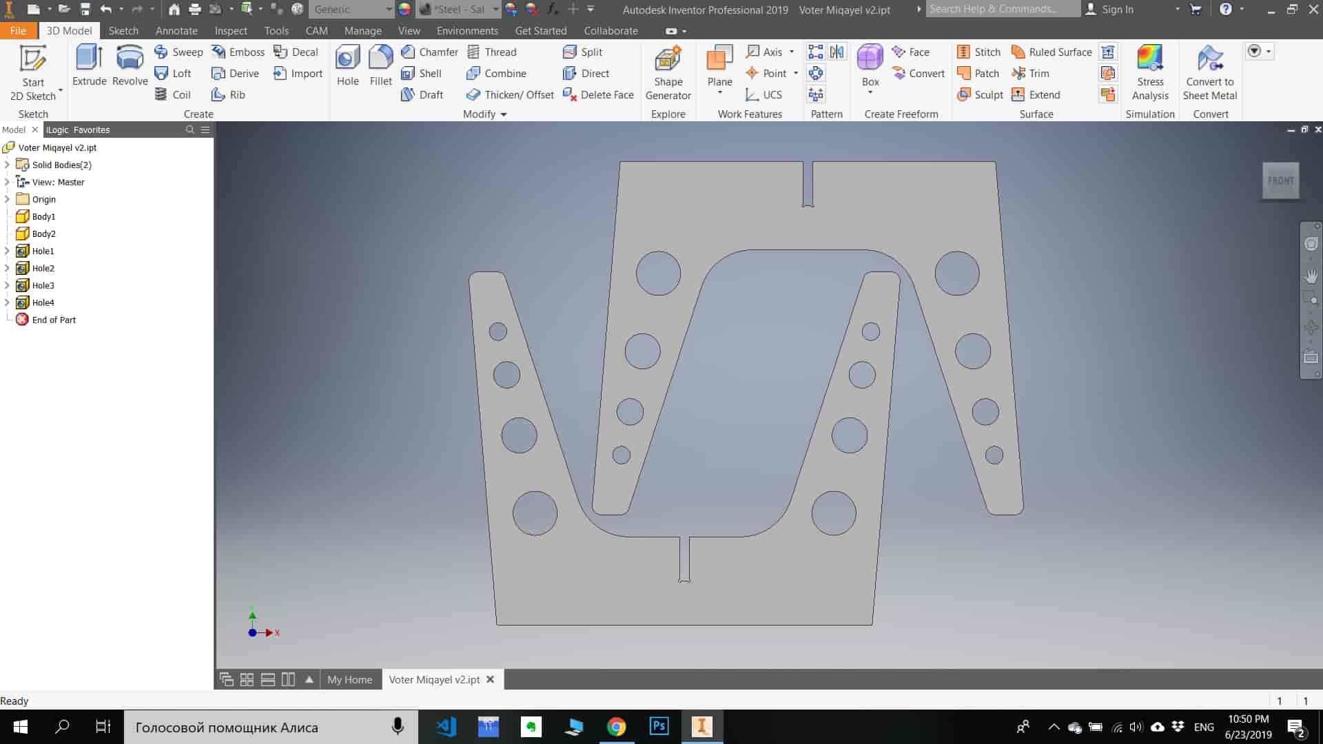
In my case, I sketched skiing by using Autodesk inventor pro. First I make measurements on my material, so I make sure that my 3D model will fit in the material. The center of skiing must be thicker than at the corners (16mm center, 8 mm corners ). After finalizing my model I exported it to a .stl file format.
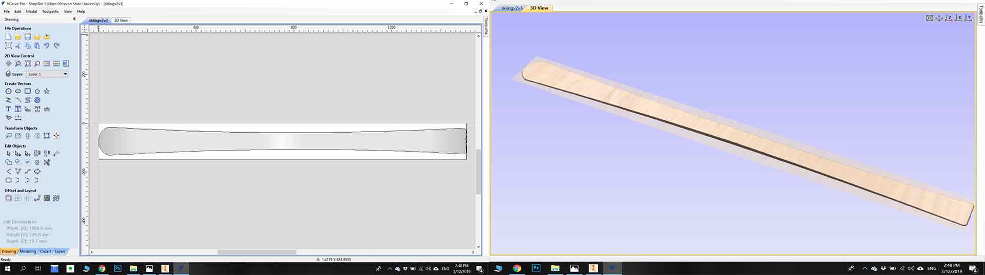
Step 1.2) Editing with VCarve Pro.
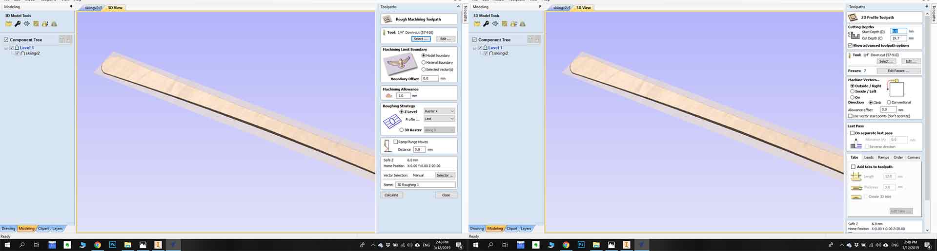
The First I set ” Job Dimensions and origins”. Second I import my 3D model by going to “Modeling > Import the component or 3D model” after I applied Smooth filters to selected components and Also “Create Vector Boundary ”.Next is “Toolpaths”, for Toolpathes first go to “3D Rounding Toolpath” and set “¼ inch Down Cut ” mill and calculate it, after go to “3D Finishing Toolpath” and set “⅛ inch Ball Nose” mill and calculate it , and finally for cut out “Profile Toolpath” by choosing outline vector and “¼ inch Down Cut ” mill I calculated it . After checking all Toolpaths with “Preview Toolpath” save all G codes files by going to “Save Toolpaths” and pressing “Save Toolpath(s) to File“.
Step 2)Cutting on ShopBot
Step 2.1)Read the instruction.
1. READ. Read this manual well to acquaint yourself with how to handle the tool safely and effectively before use. Read related manuals for the router and/or spindle that will be mounted on your ShopBot.
2. PRACTICE. Practice operating your ShopBot tool with your computer and the ShopBot Control Software BEFORE activating the router or spindle.
 Step 2.2)Fix your material on the surface Turn on ShopBot.
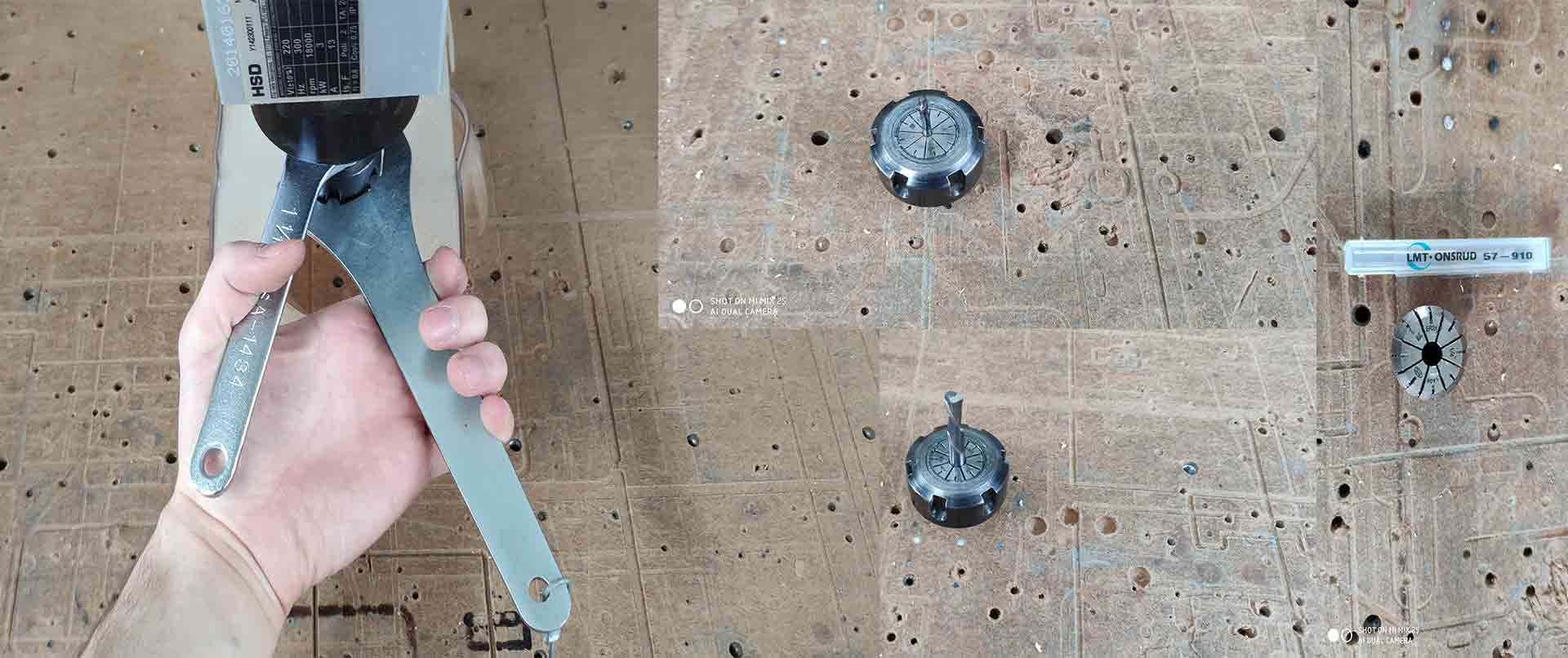
Step 2.3)Change the mill(if you need to another mill, in my case it’s “¼ inch Down Cut ”).
Step 2.4)Zero the axis.
Step 2.5)Turn on the Vacuum cleaner, plug key back and rotate.
Step 2.6)Press cut the part and “START” button.
Step 2.7)After It finishes first cut rotate the key and change the mill to “⅛ inch Ball Nose”.
Step 2.8)After It finishes the second cut rotate the key and change the mill to “¼ inch Down Cut".
Step 2.9)Finally you can take your part.
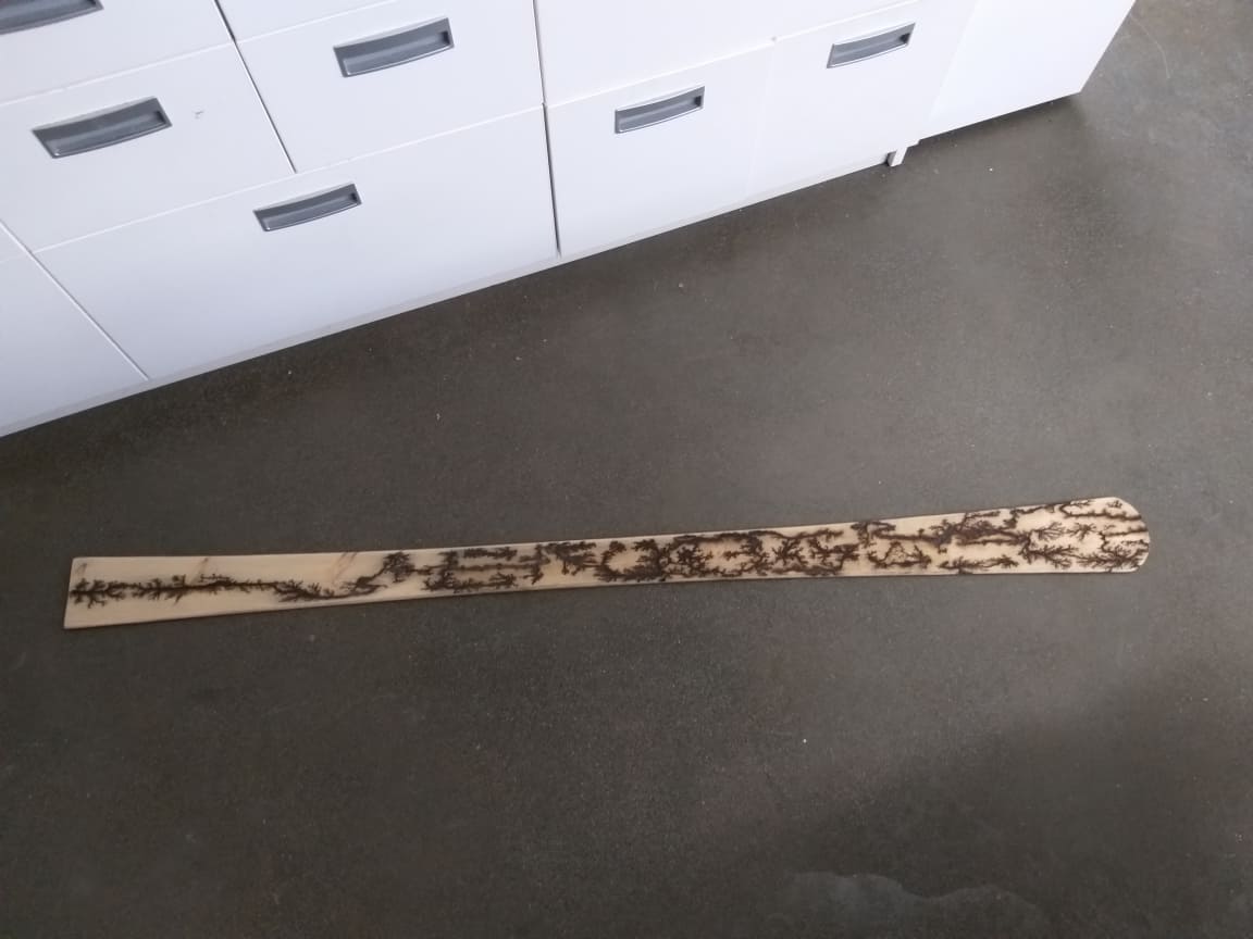
Step 3) Engraving with high voltage.
Step 3.1)For engraving on wood with high voltage you need, microwave transformation 2000V AC, water and soda mixture and two screws and wires.
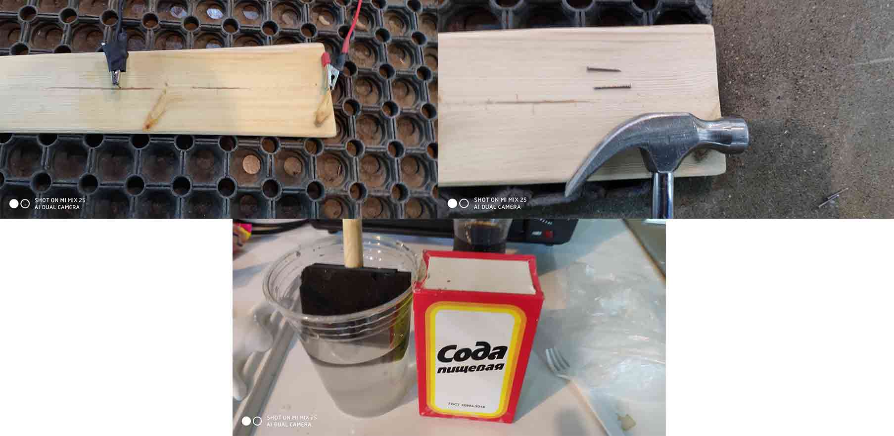
Step 3.2) put the mixture on the surface of the wood.
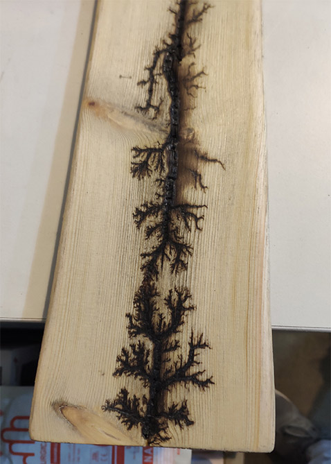
Step 3.3) Fix the screws(20cm from each other).
Step 3.4) Wire and turn Transformer on.
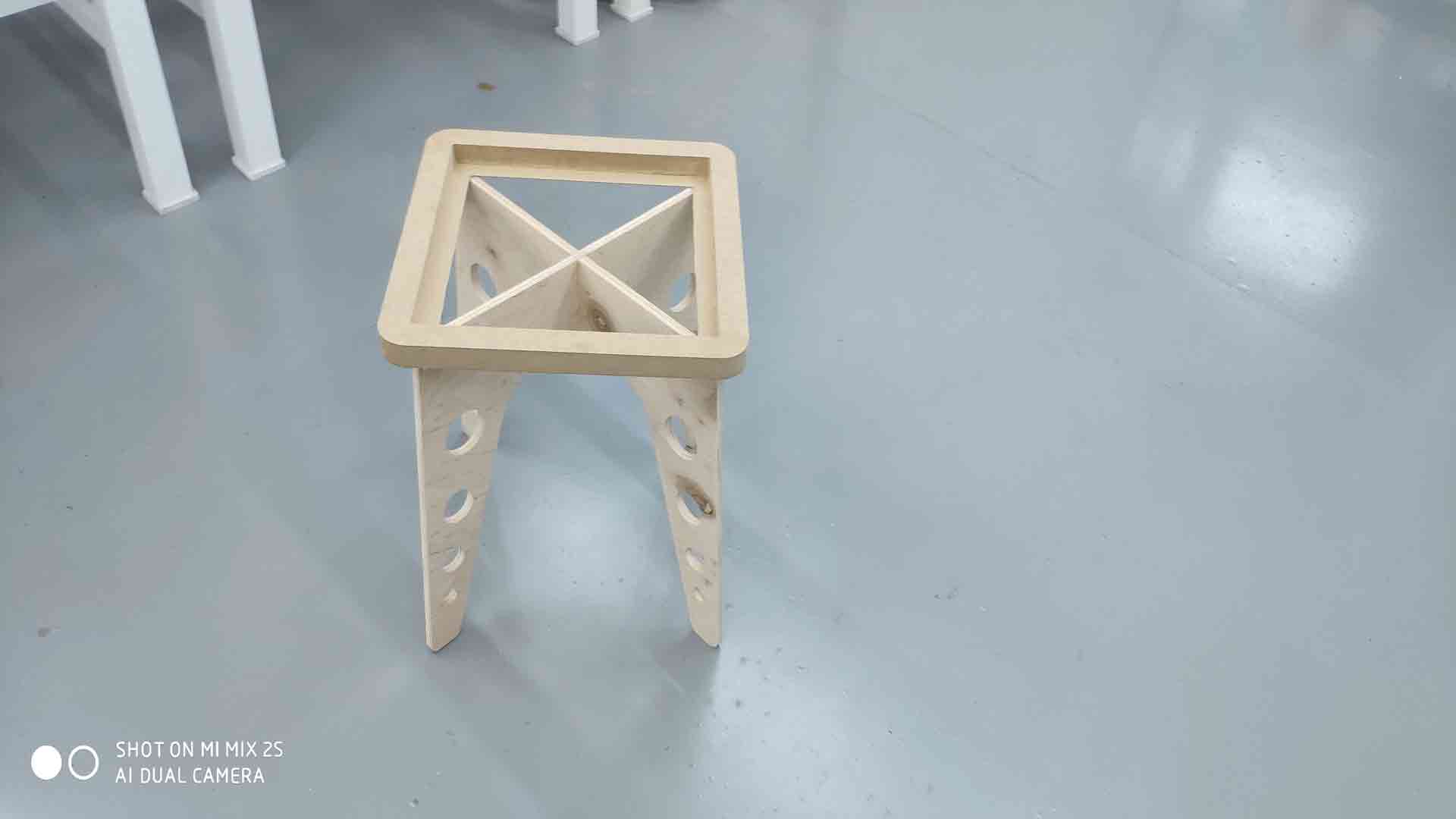
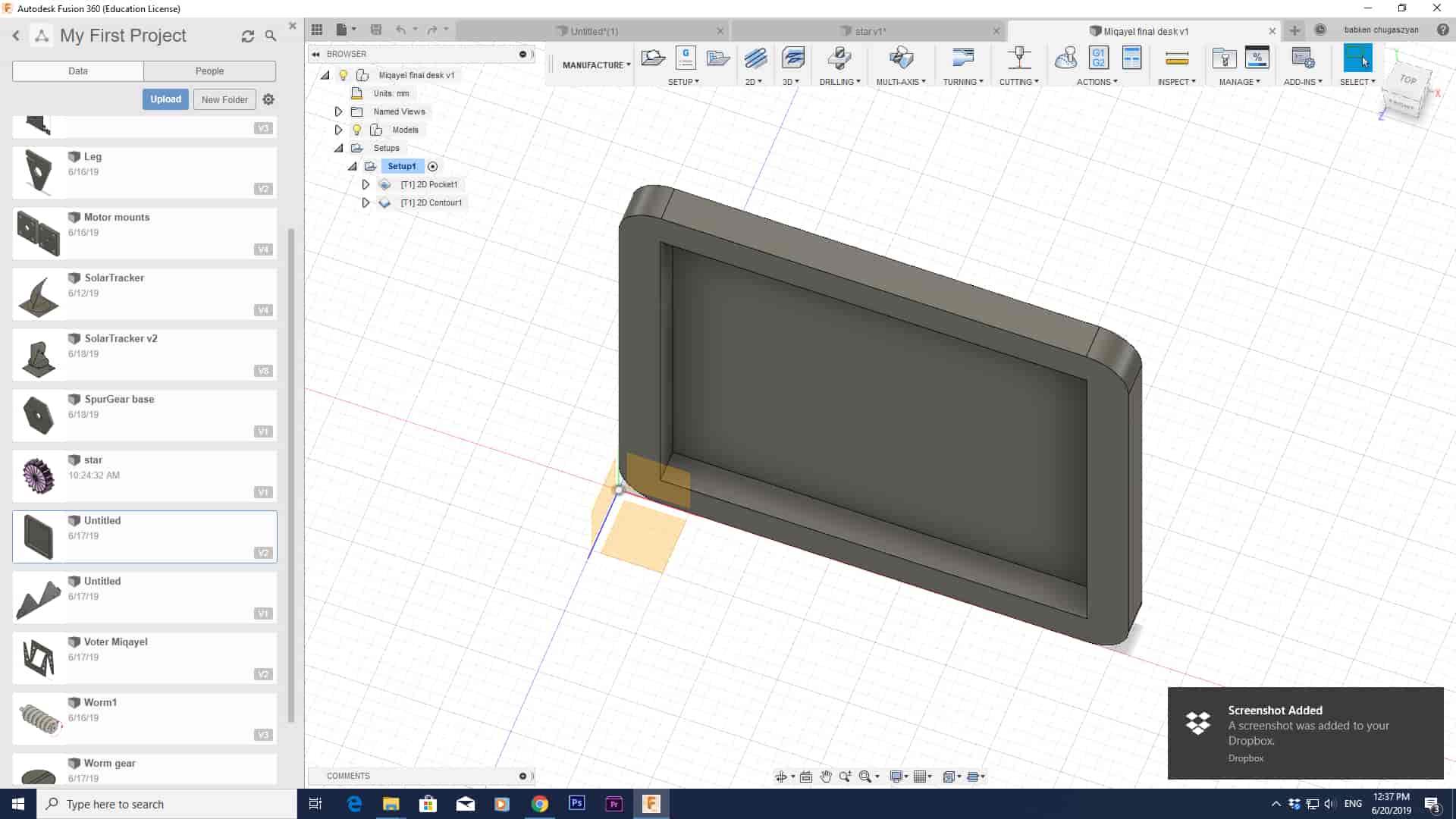
Computer-controlled machining processes
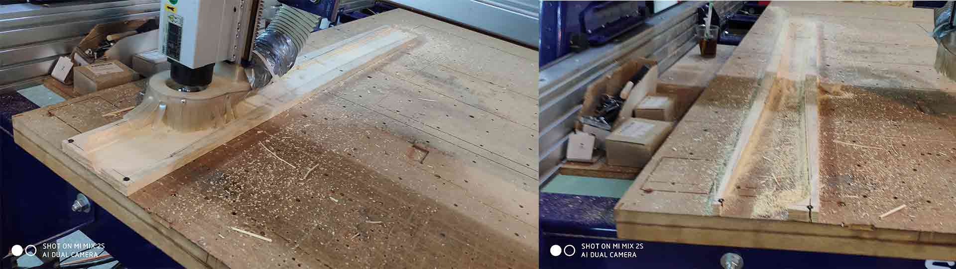
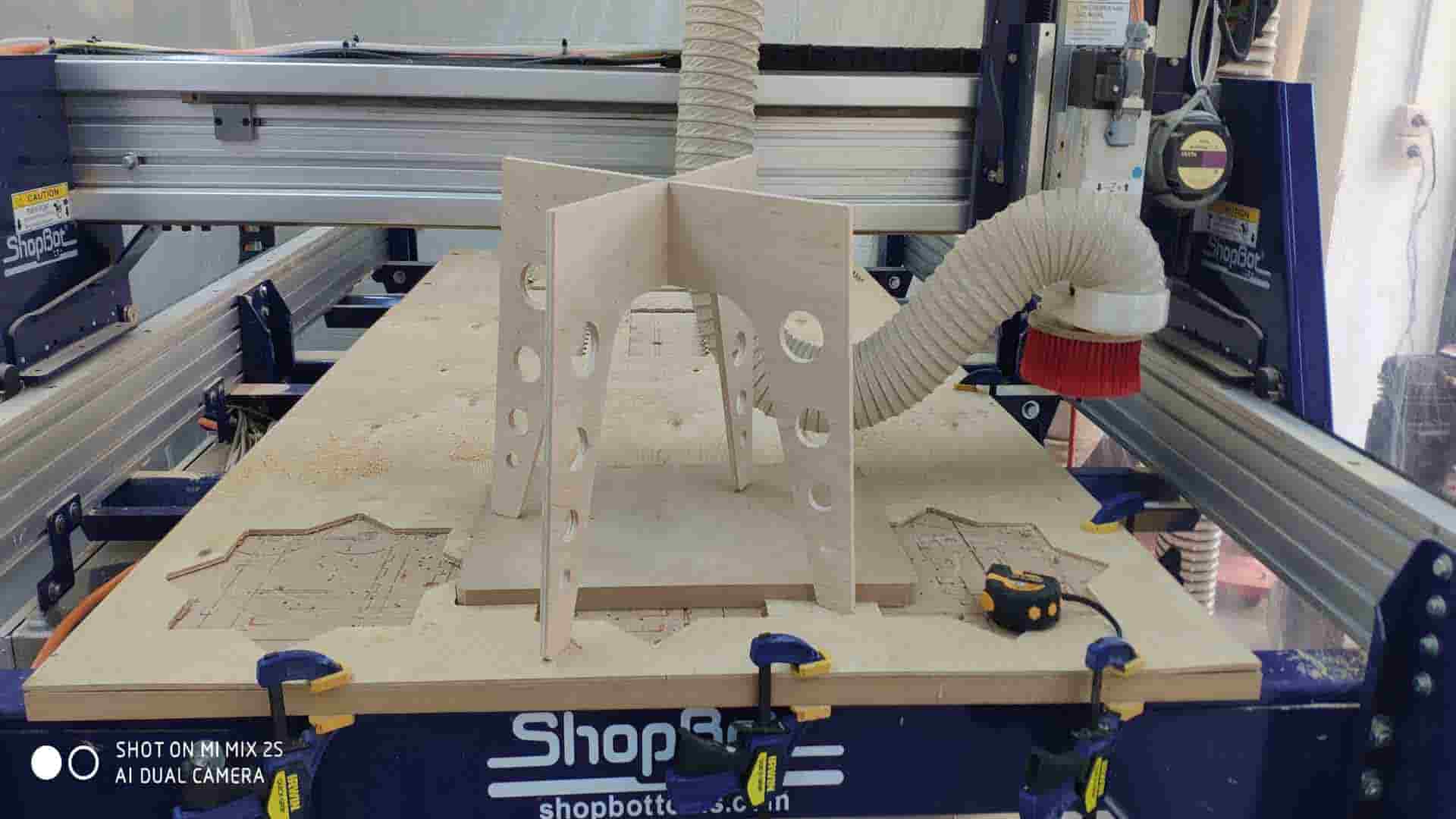
On Computer-controlled machining processes I need to cut the legs and surface of the desk using ShopBot. I have created 2 3D models one for Surface and one for legs using Fusion 360 and Audodesk Inventor Pro. I generated g code for ShopBot using Fusion manufacturing tools. For legs, I cut plywood 10mm thick using 1/8 inch tool(LMT ONSRUD 57-240 1/8”). For Surface cutting I used MDF 25mm think using 1/4 inch tool(ONSRUD 57-910 1/4“).
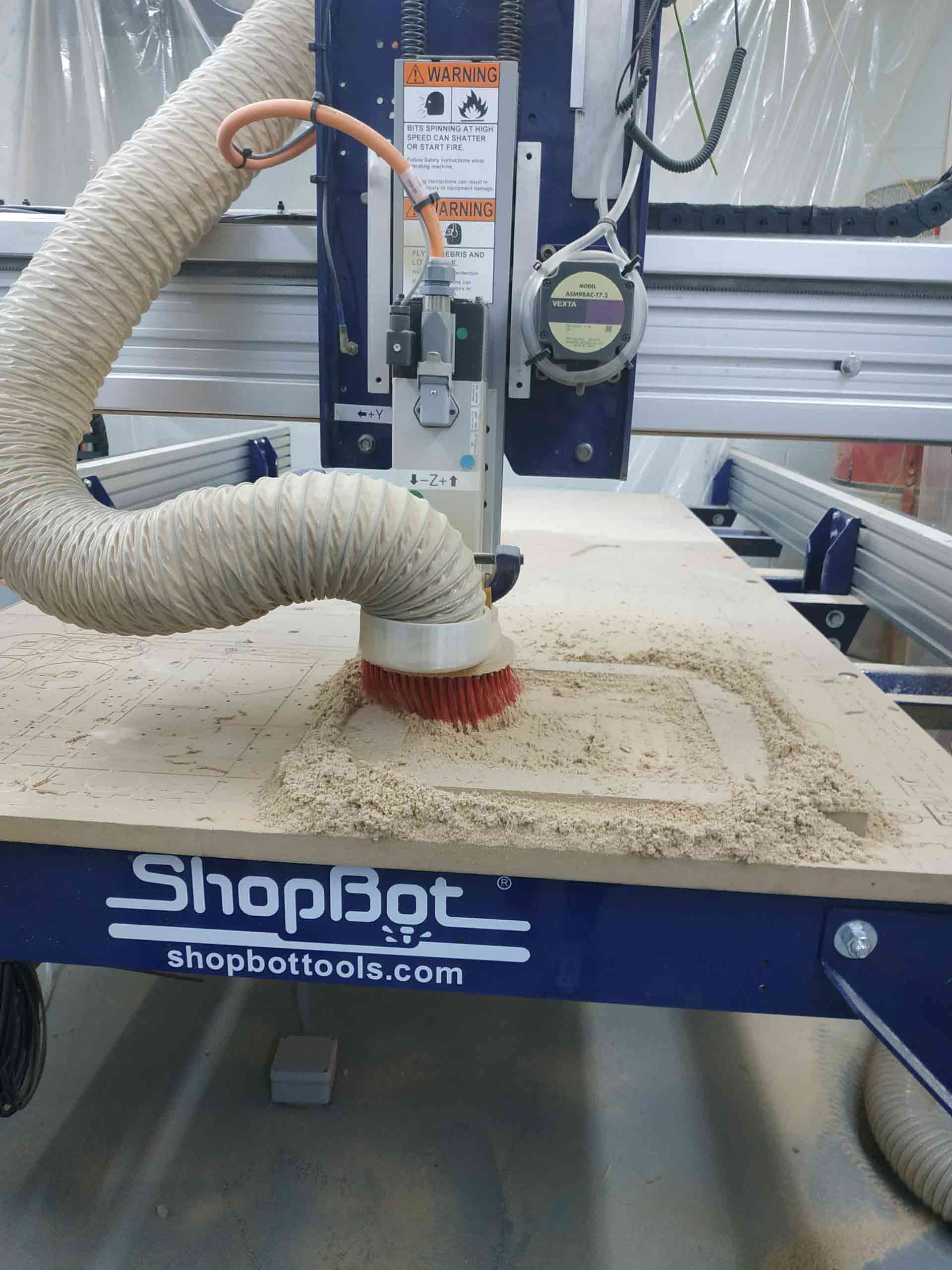
When MDF or other wood sheet is cut, a large number of dust particles are released into the air. It's important a respirator is worn and that the material is cut in a controlled and ventilated environment. It's good practice to seal exposed edges to limit emissions from binders contained in this material. So I turned on vacuum cleaner when I started to cut MDF.
When I cuted plywood (which is soft wood) I have given this parametrs for 1/8 inch end mill
And for MDF I have given this parametrs(for 1/4 inch end mill)
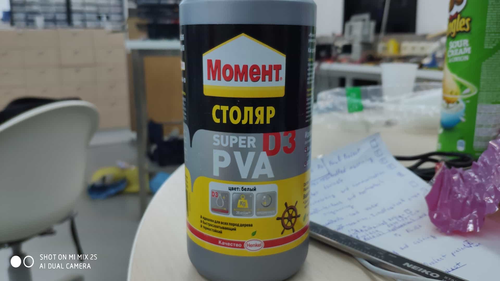
After successfully cutting all parts, I snap legs together and it was quite good (dog bonnes worked). I glue Srface and legs using Super D3 PVA glue for wood (30kg/cm^2) and leave for 40 min to dry.
Final Assembly is to try to fit 3D surface into the desk, and it was very successful, it fits perfectly.