#Week 14 / Embedded Networking and Communications
Assignment and learning outcomes.
What is this week assignment?
For this week as a group assignment we must send a message between two projects (assignments made by different students), it means we must send the messages by wire, Bluetooth, wifi or in another way. And as an individual assignment, we must design and build boards for wired or wireless node(s) with network or bus addresses.
What I gonna do this week?
This week, first of all, I want to make serial bus using RS-232 asynchronous serial bus . Also If I have time I will make a board which has Bluetooth module on it for wireless communication. I what to connect to the module by using my phone, and send messages and have communication.
RS-232, RS-422, and RS-485 Serial Data Standards
Three common serial data standards, RS-232, RS-422, and RS-485, are described by specification and electrical interface. Cable termination techniques, use of multiple loads, daisy-chaining of RS-232, conversion of RS-232 to RS-485, conversion of RS-485 to RS-232, and RS-232 port-powered RS-485 conversions are described.
RS-232 Electrical Specifications and a Typical Connection The RS-232 link was initially intended to support modem and printer applications on IBM PCs, however, it now enables a variety of peripherals to communicate with PCs. The RS-232 standard was defined as a single-ended standard for increasing serial-communication distances at low baud rates (20kbps). Over the years the standard changed to accommodate faster drivers like the MAX3225E, which offers 1Mbps data-rate capability. For RS-232 compliance, a transceiver such as the MAX3225E must meet the electrical specifications listed down bellow. A typical connection shows the use of hardware handshaking to control the flow of data.
RS-232 Summary of Major Electrical Specifications
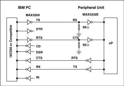
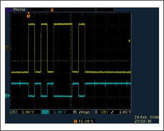
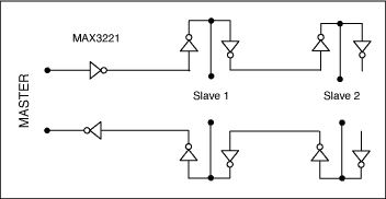
A typical RS-232 signal (CH1) swings positive and negative. Note the relative location of the 0V trace markers on the left axis. Although the RS-232 data is inverted, an overall translation from TTL/CMOS to RS-232 and back to TTL/CMOS restores the data's original polarity. Typical RS-232 transmissions seldom exceed 100 feet for two reasons. Firstly, the difference between transmitted levels (±5V) and receive levels (±3V) allows only 2V of common-mode rejection. Secondly, the distributed capacitance of a longer cable can degrade slew rates by exceeding the maximum specified load (2500pF). Because the RS-232 was designed as a point-to-point rather than multidrop interface, its drivers are specified for single loads from 3kΩ to 7kΩ. Therefore, a daisy-chain scheme is typically implemented for multidrop interface applications .
Boards design and manufacturing
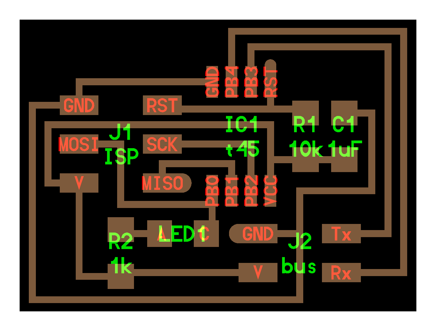
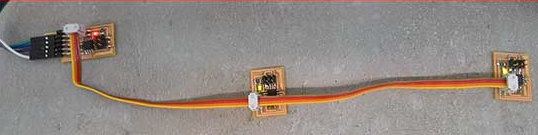
For this week assignment I desided to use Neils hello.bus.45 boards (Bridg and Nodes) to make communication between Nodes and bridge. Also I will use Neils code as base to program boards.
Generaing G code
I chose Fab modules which is perfect for exporting files for SRM-20 . Also there is desktop version which you can download on your computer but I used the web version which is very easy to use .
Step 1.1) Go to http://kokompe.cba.mit.edu/ .Step 1.2) Go to current: http://fabmodules.org/ .
Step 1.3) Choose the image format and import it on website .The available formats.
- .png
- .svg
- .stl
- .vol
 Step 1.4) Import the image of your PCB In .png or another format .
- I download FabISP layout and cutout images from here .
- Also you can design your own PCB and export it in .png format .
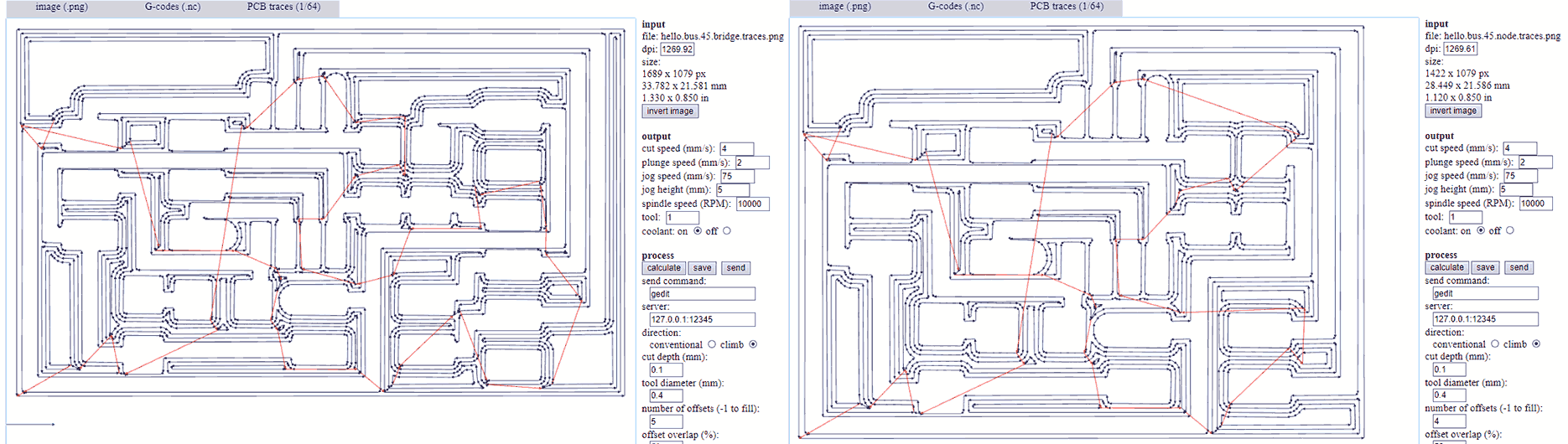
Step 1.6) Choose 1/64 inch tool for traces .
Step 1.7) Adjust the parameters .
- cut depth
- tool diameter
- number of offsets
- offset overlap
- path error
- image threshold
Step 1.8) Press “Save” and save somewhere .
Step 1.9) Restart the page choose outline image and choose 1/32 inch tool for it (the file format is the same .nc ) . You can change the parameters , but I prefer to save it by default . And after saving the you got 2 files one for layout and one for cutout .
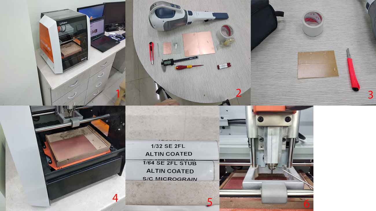
Milling
To cut our board we follow to this steps.First Clean up the area of machine , and board (make sure there is no oil on it).Make shure you got all tools
Stick Double-sided tape on the board tightly .mount board inside the machine .Choose tool (for layout 1/64 inch,for cutout and holes 1/34 inch).Tight the tool in the spindle (By holding with the finger). Before starting these steps you must read the manual. Open Vpanel for SRM-20, choose G54 in “Set Origin Point ” on the right side, choose G54 in the left side,go to Setup and choose “RML-1/NC Code ”, choose the tool , at first 1/64 inches . (If you have not done it yet ), tight the tool in the spindle.(If you have not done it yet ).)Move the tool wherever you what to zero it (You can move it by using buttons in the middle +Y , -Y , +X , -X , +Z, -Z(be carefully with Z), you can adjust the speed of movement in “Cursor Step ” section ).
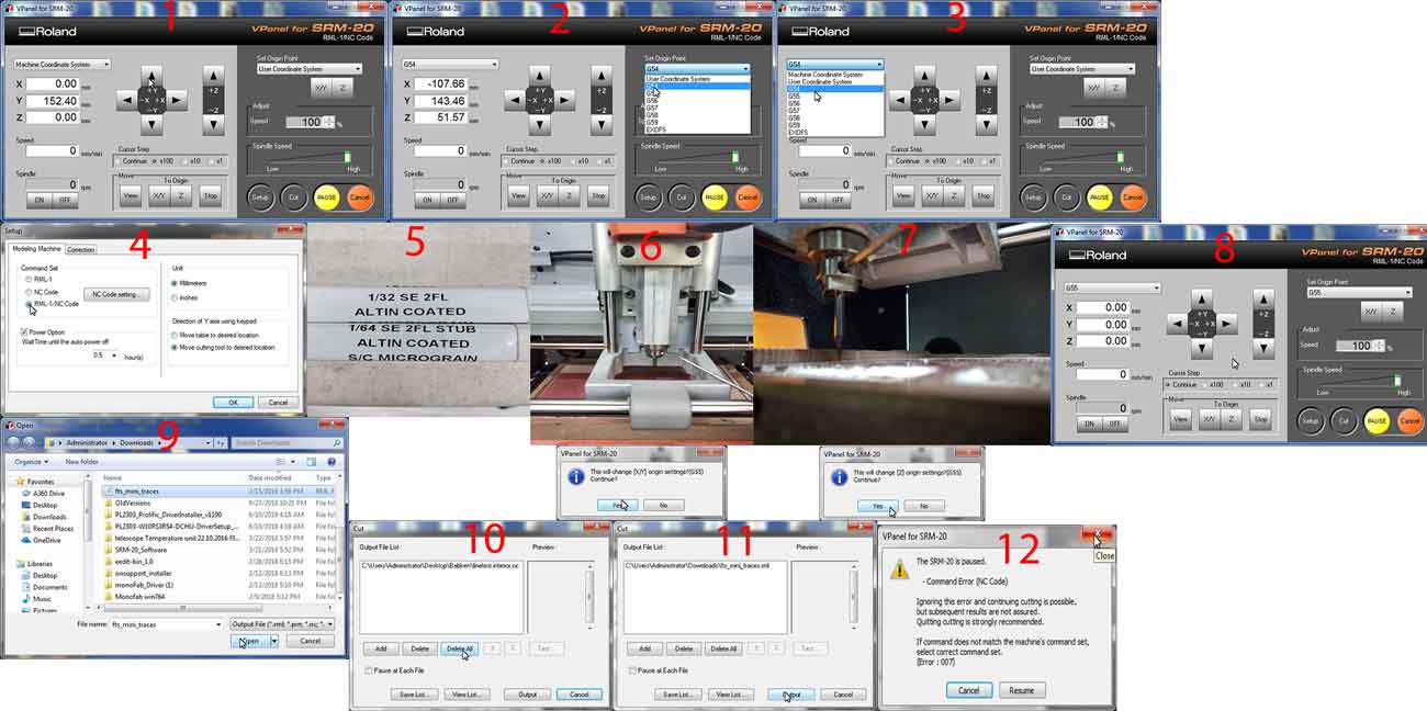
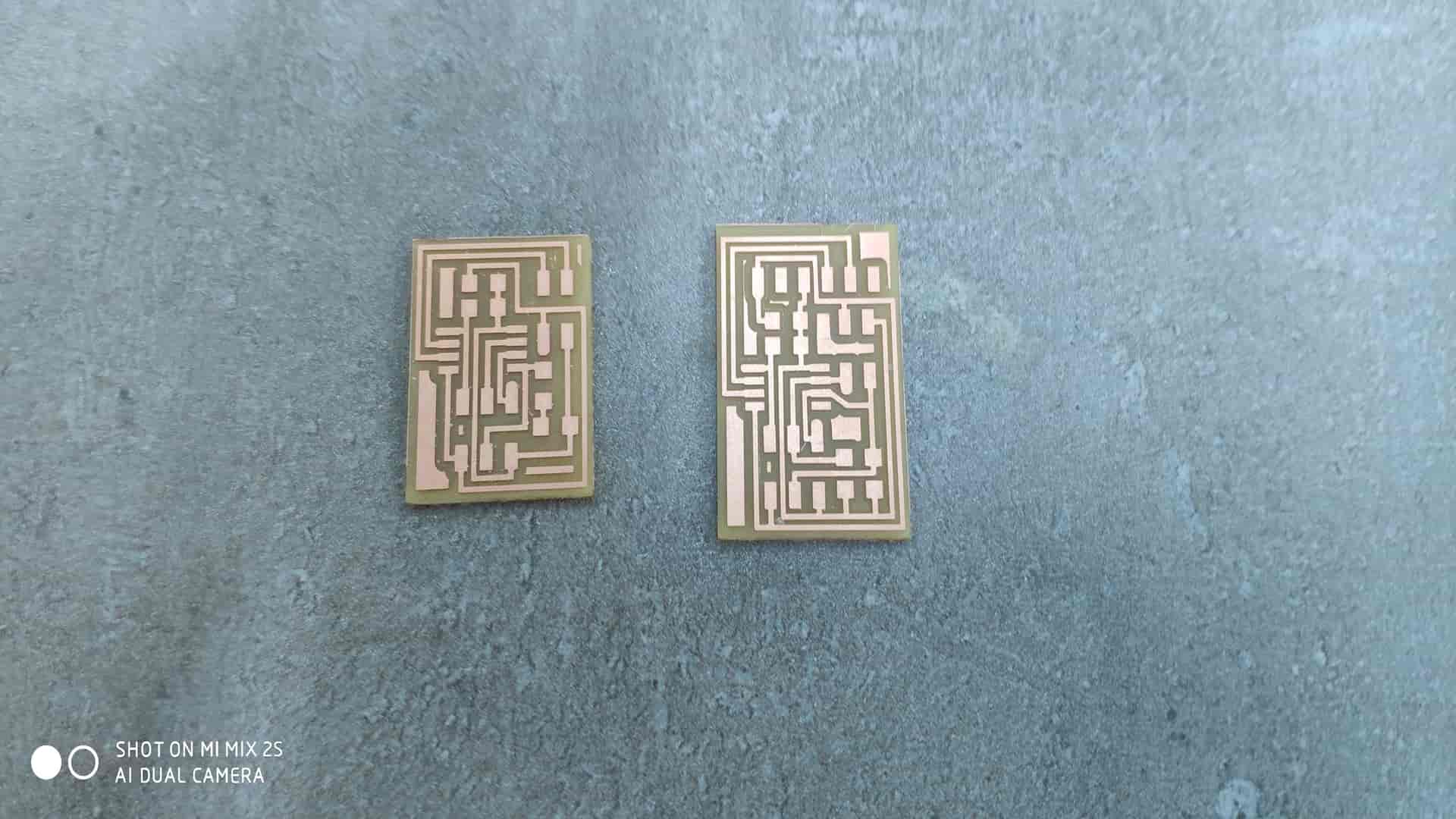
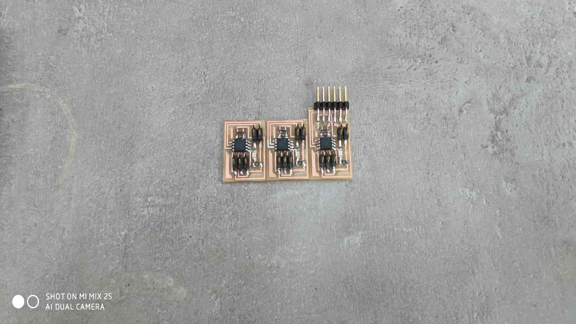
Press “X/Y” on the right side and click “Yes” , and press “Z” “Yes ” , it will change the origins by 0.)Make sure you have generated the files in Step 1 .Click “Cut” and press “Delete All”.Press add button and choose the g-code file . At first 1/64 inches file and press output .Press “Red X ” , and the machine will start the milling proces .)When it finish , press “View” button in the “Move” section .Change the tool to 1/32 inches .Zero the Z origin .Output the cut out file .And finaly will get the board .The same process we have done on group project , and got this .
Soldering
Before starting soldering clean up the space around and make sure you have all supplys.
also all components for hello.bus.45.bridge board needs
and hello.bus.45.node board needs
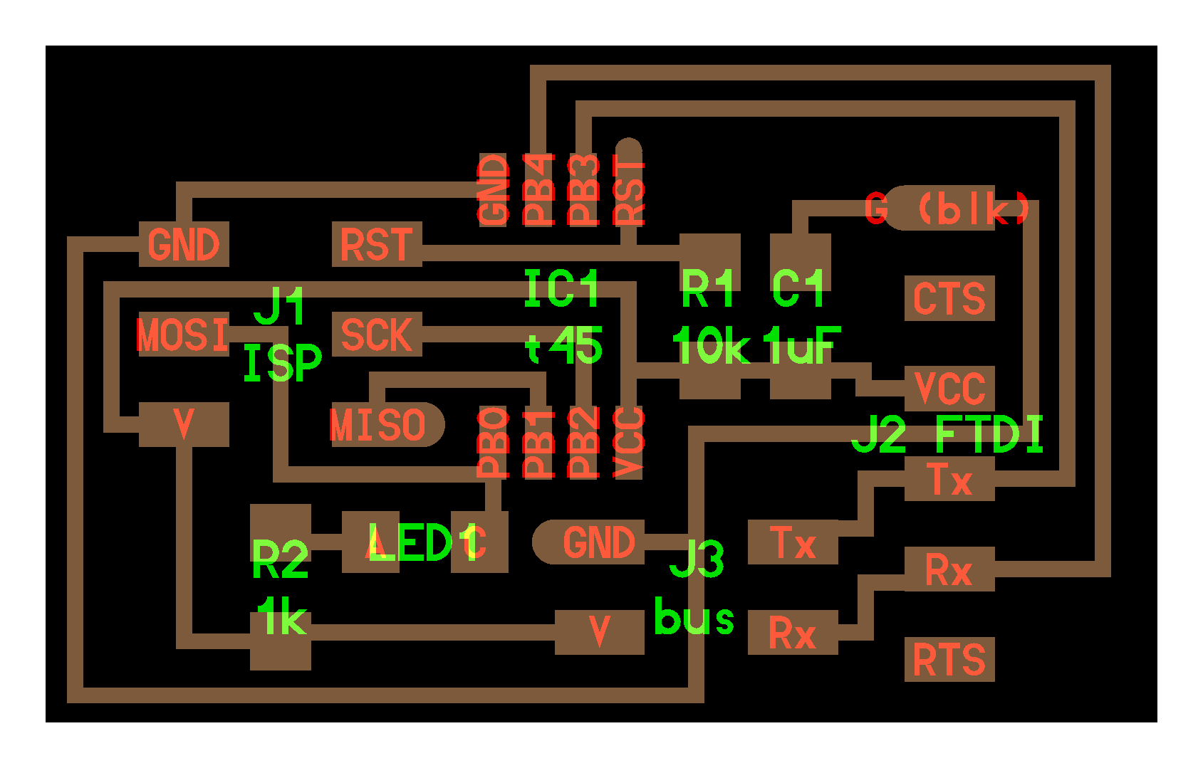
Remove unnecessary parts on the board with cutter .Clean up your PCB with water . Water the soldering iron sponge .Start Soldering(Solder by looking on schematics and layout .I added a jumper , after programming you can put it in one pin )
Programming
For programming board I used FabISP I made on week5 and FTDI cabel for serial communicate.Connect your usbtiny (FabISP) to the hello.bus.45.bridge board's ISP port using the ISP cable, connect FTDI cable to board's FTDI pins and connect FabISP to the USB port of the computer.
In order to program board I need
cd to network folder and enter make -f hello.bus.45.make program-usbtiny command. -f scecifies the makefile's name in this case it's "hello.bus.45.make"
program- specifies the programmer we're going to use in our case "usbtiny"
(!!! if you use other programmer change "usbtiny" to "avrisp2" or "dragon_isp" !!!).
Overall this command makes the .hex file based on the libraries and the C code.
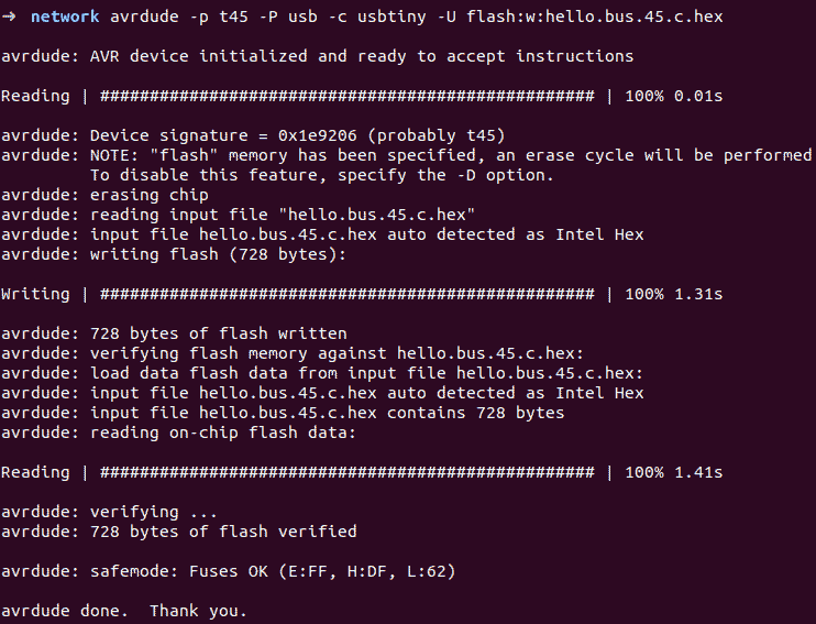
If everything goes right you should see this message. After type avrdude -p t45 -P usb -c usbtiny -U flash:w:hello.bus.45.c.hex -p scecifies the AVR device in our case t45 (ATtiny45)
-P specifies the connection port in our case USB port (FabISP)
-c specifies the programmer type in our case it's usbtiny
(!!! if you use other programmer change "usbtiny" to "avrisp2" or "dragon_isp" !!!).
-U specifies a memory operation (multiple options available)
in our case "flash" flashes the ROM, "w" reads the .hex file and writes it to the memory.
If everything goes right you should see this message. Congradulations you're done!. Close the terminal.
In order to make connection between briage and nodes we to make 4 wire ribbon cable about 30cm and 4 2x2 connectors.Now go ahead and find the #define node_id '0' line in the C code and change '0' to '1' in order to have unique id for each board. Save the file. Connect your usbtiny (FabISP) to the node board's ISP port using the ISP cable as shown in the image above.Agan open the "network" folder right click and select "Open in Terminal" option again type this command (or hit up arrow key and find this command) and hit enter:
-f hello.bus.45.make program-usbtiny. Next type this command (or hit up arrow key and find this command) and hit enter
avrdude -p t45 -P usb -c usbtiny -U flash:w:hello.bus.45.c.hex. Now find #define node_id '1' line in the C code and change '1' to '2' in order to have unique id for next board. Save the file. Connect your usbtiny (FabISP) to the next node board's ISP port using the ISP cable as shown in the image below. Agan open the "network" folder right click and select "Open in Terminal" option again type this command (or hit up arrow key and find this command) and hit enter:
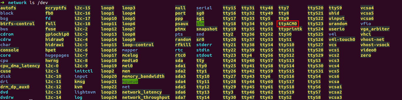
make -f hello.bus.45.make program-usbtiny. Next type this command (or hit up arrow key and find this command) and hit enter avrdude -p t45 -P usb -c usbtiny -U flash:w:hello.bus.45.c.hex.Remove the ISP cable. Download term.py to the same "network" folder. You need term.py to send and monitor serial data. Open the "network" folder right click and select "Open in Terminal". Type this command ls /dev ls /dev and hit enter. This command lists the devices connected.In our case our FabFTDI is listed as ttyACM0. In case of FTDI cable it should be ttyUSB0.
Now type this command sudo python term.py /dev/ttyACM0 4800 (if you use FTDI cable change 4800 to 9600 and ttyACM0 to ttyUSB0.) hit enter.
Code
		//
		//
		// hello.bus.45.c
		//
		// 9600 baud serial bus hello-world
		//
		// Neil Gershenfeld
		// 11/24/10
		//
		// (c) Massachusetts Institute of Technology 2010
		// Permission granted for experimental and personal use;
		// license for commercial sale available from MIT.
		//

		#include avr/io.h>
		#include util/delay.h>
		#include avr/pgmspace.h>
		#include string.h>

		#define output(directions,pin) (directions |= pin) // set port direction for output
		#define input(directions,pin) (directions &= (~pin)) // set port direction for input
		#define set(port,pin) (port |= pin) // set port pin
		#define clear(port,pin) (port &= (~pin)) // clear port pin
		#define pin_test(pins,pin) (pins & pin) // test for port pin
		#define bit_test(byte,bit) (byte & (1 << bit)) // test for bit set
		#define bit_delay_time 100 // bit delay for 9600 with overhead
		#define bit_delay() _delay_us(bit_delay_time) // RS232 bit delay
		#define half_bit_delay() _delay_us(bit_delay_time/2) // RS232 half bit delay
		#define led_delay() _delay_ms(100) // LED flash delay

		#define led_port PORTB
		#define led_direction DDRB
		#define led_pin (1 << PB0)

		#define serial_port PORTB
		#define serial_direction DDRB
		#define serial_pins PINB
		#define serial_pin_in (1 << PB3)
		#define serial_pin_out (1 << PB4)

		#define node_id '0'

		void get_char(volatile unsigned char *pins, unsigned char pin, char *rxbyte) {
		   //
		   // read character into rxbyte on pins pin
		   //    assumes line driver (inverts bits)
		   //
		   *rxbyte = 0;
		   while (pin_test(*pins,pin))
			  //
			  // wait for start bit
			  //
			  ;
		   //
		   // delay to middle of first data bit
		   //
		   half_bit_delay();
		   bit_delay();
		   //
		   // unrolled loop to read data bits
		   //
		   if pin_test(*pins,pin)
			  *rxbyte |= (1 << 0);
		   else
			  *rxbyte |= (0 << 0);
		   bit_delay();
		   if pin_test(*pins,pin)
			  *rxbyte |= (1 << 1);
		   else
			  *rxbyte |= (0 << 1);
		   bit_delay();
		   if pin_test(*pins,pin)
			  *rxbyte |= (1 << 2);
		   else
			  *rxbyte |= (0 << 2);
		   bit_delay();
		   if pin_test(*pins,pin)
			  *rxbyte |= (1 << 3);
		   else
			  *rxbyte |= (0 << 3);
		   bit_delay();
		   if pin_test(*pins,pin)
			  *rxbyte |= (1 << 4);
		   else
			  *rxbyte |= (0 << 4);
		   bit_delay();
		   if pin_test(*pins,pin)
			  *rxbyte |= (1 << 5);
		   else
			  *rxbyte |= (0 << 5);
		   bit_delay();
		   if pin_test(*pins,pin)
			  *rxbyte |= (1 << 6);
		   else
			  *rxbyte |= (0 << 6);
		   bit_delay();
		   if pin_test(*pins,pin)
			  *rxbyte |= (1 << 7);
		   else
			  *rxbyte |= (0 << 7);
		   //
		   // wait for stop bit
		   //
		   bit_delay();
		   half_bit_delay();
		   }

		void put_char(volatile unsigned char *port, unsigned char pin, char txchar) {
		   //
		   // send character in txchar on port pin
		   //    assumes line driver (inverts bits)
		   //
		   // start bit
		   //
		   clear(*port,pin);
		   bit_delay();
		   //
		   // unrolled loop to write data bits
		   //
		   if bit_test(txchar,0)
			  set(*port,pin);
		   else
			  clear(*port,pin);
		   bit_delay();
		   if bit_test(txchar,1)
			  set(*port,pin);
		   else
			  clear(*port,pin);
		   bit_delay();
		   if bit_test(txchar,2)
			  set(*port,pin);
		   else
			  clear(*port,pin);
		   bit_delay();
		   if bit_test(txchar,3)
			  set(*port,pin);
		   else
			  clear(*port,pin);
		   bit_delay();
		   if bit_test(txchar,4)
			  set(*port,pin);
		   else
			  clear(*port,pin);
		   bit_delay();
		   if bit_test(txchar,5)
			  set(*port,pin);
		   else
			  clear(*port,pin);
		   bit_delay();
		   if bit_test(txchar,6)
			  set(*port,pin);
		   else
			  clear(*port,pin);
		   bit_delay();
		   if bit_test(txchar,7)
			  set(*port,pin);
		   else
			  clear(*port,pin);
		   bit_delay();
		   //
		   // stop bit
		   //
		   set(*port,pin);
		   bit_delay();
		   //
		   // char delay
		   //
		   bit_delay();
		   }

		void put_string(volatile unsigned char *port, unsigned char pin, PGM_P str) {
		   //
		   // send character in txchar on port pin
		   //    assumes line driver (inverts bits)
		   //
		   static char chr;
		   static int index;
		   index = 0;
		   do {
			  chr = pgm_read_byte(&(str[index]));
			  put_char(&serial_port, serial_pin_out, chr);
			  ++index;
			  } while (chr != 0);
		   }

		void flash() {
		   //
		   // LED flash delay
		   //
		   clear(led_port, led_pin);
		   led_delay();
		   set(led_port, led_pin);
		   }

		int main(void) {
		   //
		   // main
		   //
		   static char chr;
		   //
		   // set clock divider to /1
		   //
		   CLKPR = (1 << CLKPCE);
		   CLKPR = (0 << CLKPS3) | (0 << CLKPS2) | (0 << CLKPS1) | (0 << CLKPS0);
		   //
		   // initialize output pins
		   //
		   set(serial_port, serial_pin_out);
		   input(serial_direction, serial_pin_out);
		   set(led_port, led_pin);
		   output(led_direction, led_pin);
		   //
		   // main loop
		   //
		   while (1) {
			  get_char(&serial_pins, serial_pin_in, &chr);
			  flash();
			  if (chr == node_id) {
				 output(serial_direction, serial_pin_out);
				 static const char message[] PROGMEM = "node ";
				 put_string(&serial_port, serial_pin_out, (PGM_P) message);
				 put_char(&serial_port, serial_pin_out, chr);
				 put_char(&serial_port, serial_pin_out, 10); // new line
				 led_delay();
				 flash();
				 input(serial_direction, serial_pin_out);
				 }
			  }
		   }