Embedded programming
Introduction
This week I am going to finish the board for my final project and program it. I will use atmega 328 on the board, switches, motor driver, light sensor. Embedded programming is new for me, I should learn a lot. I know about it theritically, participated in some project during university years."Some experts define embedded programming as the dominant methodology for microcontroller programming. Essentially, embedded programming involves programming small computers that drive devices. In terms of its practical implementation, embedded programming is useful in the design of software for automotive features, small facilities-handling devices like thermostats, handheld games or other small devices."
This week our assignment is to:
•Individual assignment: read a microcontroller data sheet program your board to do something, with as many different programming languages and programming environments as possible•group assignment: compare the performance and development workflow for other architectures
Microcontroller
A microcontroller (MCU for microcontroller unit, or UC for μ-controller) is a small computer on a single integrated circuit. In modern terminology, it is similar to, but less sophisticated than, a system on a chip (SoC); an SoC may include a microcontroller as one of its components. A microcontroller contains one or more CPUs (processor cores) along with memory and programmable input/output peripherals. Program memory in the form of ferroelectric RAM, NOR flash or OTP ROM is also often included on chip, as well as a small amount of RAM. Microcontrollers are designed for embedded applications, in contrast to the microprocessors used in personal computers or other general purpose applications consisting of various discrete chips. Microcontrollers are used in automatically controlled products and devices, such as automobile engine control systems, implantable medical devices, remote controls, office machines, appliances, power tools, toys and other embedded systems. By reducing the size and cost compared to a design that uses a separate microprocessor, memory, and input/output devices, microcontrollers make it economical to digitally control even more devices and processes. Mixed signal microcontrollers are common, integrating analog components needed to control non-digital electronic systems. In the context of the internet of things, microcontrollers are an economical and popular means of data collection, sensing and actuating the physical world as edge devices.
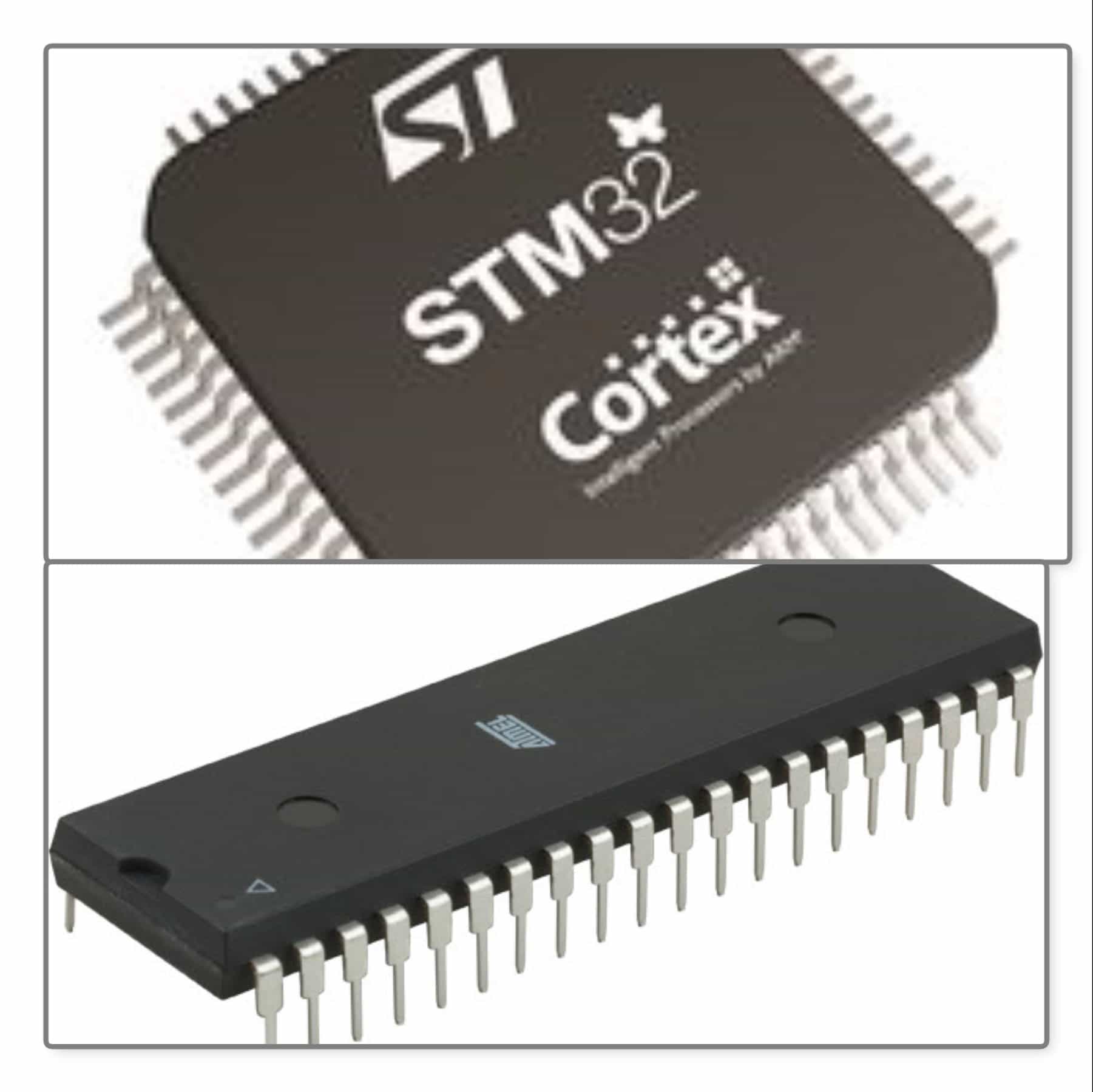
Step 1 - What is Atmega 328
I download the datasheet of Atmega 328.The ATmega 328P is a low-power CMOS 8-bit microcontroller based on the AVR enhanced RISC architecture. By executing powerful instructions in a single clock cycle, the ATmega48P/88P/168P/328P achieves throughputs approaching 1 MIPS per MHz allowing the system designer to optimize power consumption versus processing speed.
On this page you can see the features of Atmega328p microcontroler.
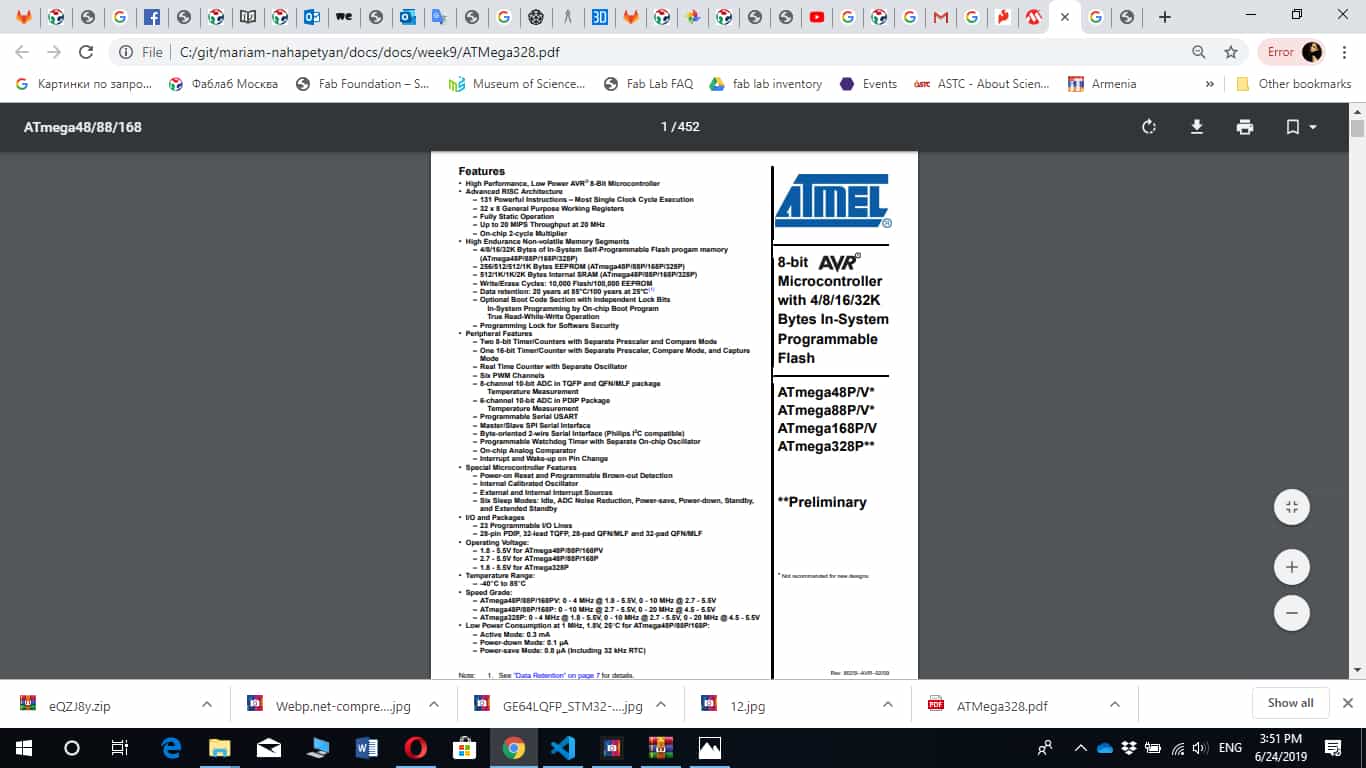 Features
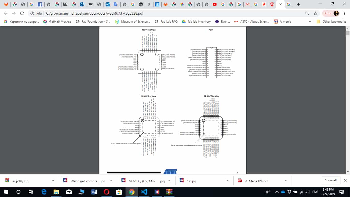
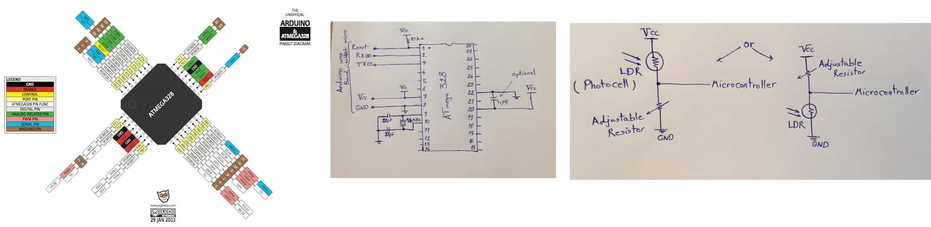
The most important in datasheet it is pin cnfiguration.
 pin
configuration
pin
configuration
Atmega328p has VCC and GND for digital voltage. In case of Internal Calibrated RC Oscillator is used as chip clock source, PB7..6 is used as TOSC2..1 input for the Asynchronous Timer/Counter2 if the AS2 bit in ASSR is set. Port C is a 7-bit bi-directional I/O port with internal pull-up resistors (selected for each bit). The PC5..0 output buffers have symmetrical drive characteristics with both high sink and source capability. As inputs, Port C pins that are externally pulled low will source current if the pull-up resistors are activated. The Port C pins are tri-stated when a reset condition becomes active, even if the clock is not running. PC6 is used as an I/O pin. Note that the electrical characteristics of PC6 differ from those of the other pins of Port C. If the RSTDISBL Fuse is unprogrammed, PC6 is used as a Reset input. A low level on this pin for longer than the minimum pulse length will generate a Reset, even if the clock is not running. The minimum pulse length is given in Table 26-3 on page 320. Shorter pulses are not guaranteed to generate a Reset. The various special features of Port C are elaborated in ”Alternate Functions of Port C” on page 85. Port D is an 8-bit bi-directional I/O port with internal pull-up resistors (selected for each bit). The Port D output buffers have symmetrical drive characteristics with both high sink and source capability. As inputs, Port D pins that are externally pulled low will source current if the pull-up resistors are activated. The Port D pins are tri-stated when a reset condition becomes active, even if the clock is not running. AVCC is the supply voltage pin for the A/D Converter, PC3:0, and ADC7:6. It should be externally connected to VCC, even if the ADC is not used. If the ADC is used, it should be connected to VCC through a low-pass filter. Note that PC6..4 use digital supply voltage, VCC. AREF is the analog reference pin for the A/D Converter. In the TQFP and QFN/MLF package, ADC7:6 serve as analog inputs to the A/D converter. These pins are powered from the analog supply and serve as 10-bit ADC channels.
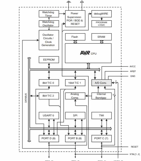
Here is the block diagram of the microcontroller
 Block
Diagram
Block
Diagram
The AVR core combines a rich instruction set with 32 general purpose working registers. All the 32 registers are directly connected to the Arithmetic Logic Unit (ALU), allowing two independent registers to be accessed in one single instruction executed in one clock cycle. The resulting architecture is more code efficient while achieving throughputs up to ten times faster than conventional CISC microcontrollers. The ATmega48P/88P/168P/328P provides the following features: 4K/8K/16K/32K bytes of InSystem Programmable Flash with Read-While-Write capabilities, 256/512/512/1K bytes EEPROM, 512/1K/1K/2K bytes SRAM, 23 general purpose I/O lines, 32 general purpose working registers, three flexible Timer/Counters with compare modes, internal and external interrupts, a serial programmable USART, a byte-oriented 2-wire Serial Interface, an SPI serial port, a 6-channel 10-bit ADC (8 channels in TQFP and QFN/MLF packages), a programmable Watchdog Timer with internal Oscillator, and five software selectable power saving modes. The Idle mode stops the CPU while allowing the SRAM, Timer/Counters, USART, 2-wire Serial Interface, SPI port, and interrupt system to continue functioning. The Power-down mode saves the register contents but freezes the Oscillator, disabling all other chip functions until the next interrupt or hardware reset. In Power-save mode, the asynchronous timer continues to run, allowing the user to maintain a timer base while the rest of the device is sleeping. The ADC Noise Reduction mode stops the CPU and all I/O modules except asynchronous timer and ADC, to minimize switching noise during ADC conversions. In Standby mode, the crystal/resonator Oscillator is running while the rest of the device is sleeping. This allows very fast start-up combined with low power consumption.
Step 2 - Figure out how to program
• Read tutorials about "C" programming language
"C is a general-purpose, high-level language that was originally developed by Dennis M. Ritchie to develop the UNIX operating system at Bell Labs. C was originally first implemented on the DEC PDP-11 computer in 1972. In 1978, Brian Kernighan and Dennis Ritchie produced the first publicly available description of C, now known as the K&R standard. The UNIX operating system, the C compiler, and essentially all UNIX application programs have been written in C."
• Start using online C compiler .• Go back to AVRs,
Setting up "C " to computer
• I need to have "text editor and C compiler" in my computer. As text editor I am using Windows notepad• I should install GCC on Windows for that I should install MinGW - download MinGW-
Made some scetches for my project
After reading datasheet and some topics about the microcontroller I uanderstood that I chose the right chip.
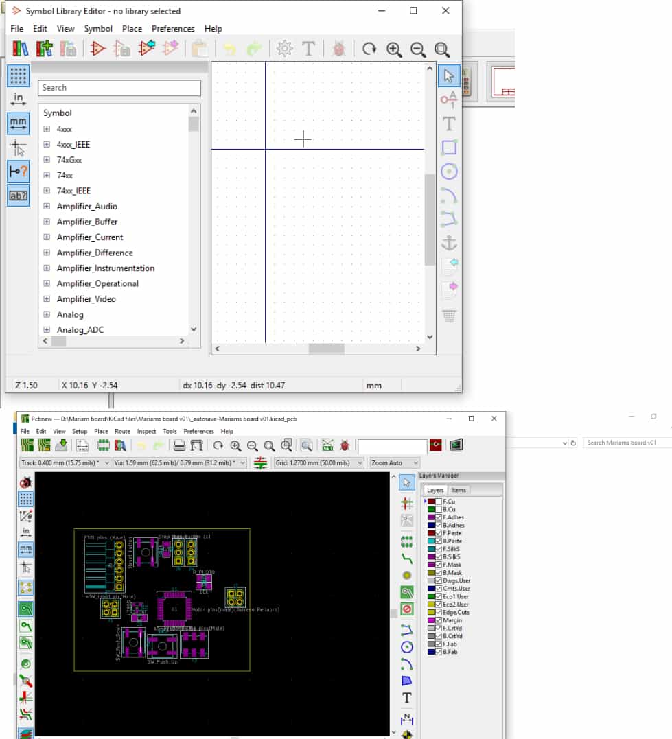
• I went back to my board finished the design of it and started cutting it. Again I used SRM-20 milling masiche, 1/64 and 1/32 endmills, fabmodules.
After the cutting I solsdered the components on the board.
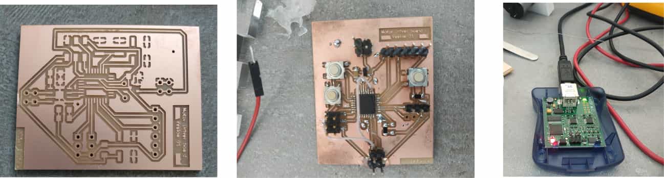
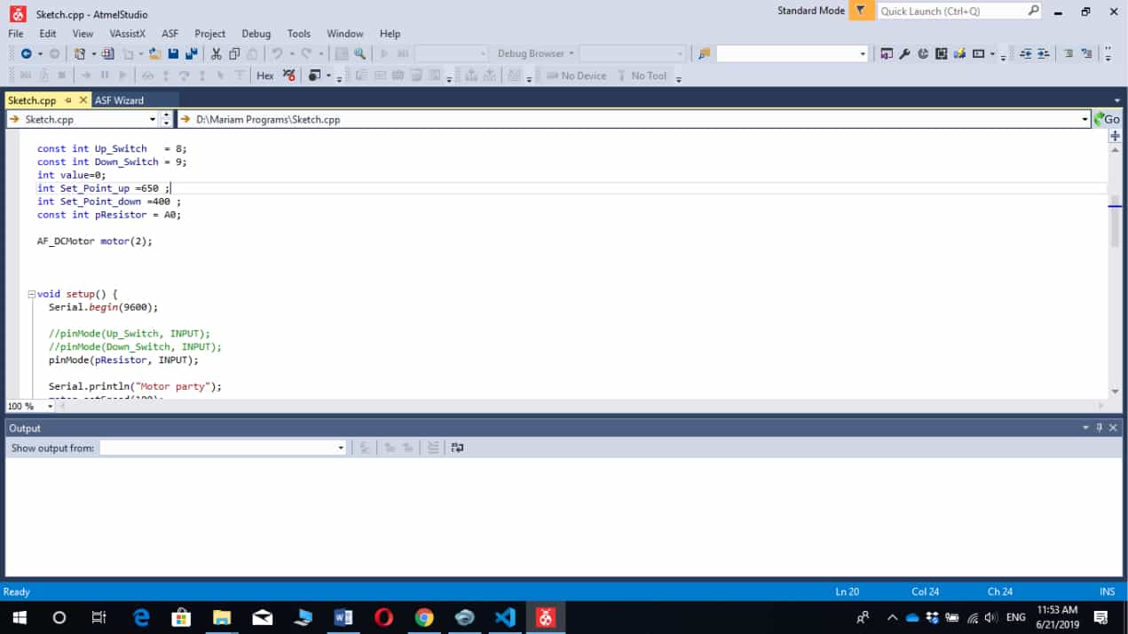
After I started writing my program, I installed Atmel Studio I used atmel-studio-7 for programming my microcontroller. I tried to write the program many times, when I finished I started trying program my board by AVR programmer. After it programmed from the first time, but had problems with programming. I reprogrammed the the board for many times untill got the necessary result. But the problem was in board the motor driver was demaged. If the light sensor send command " sunlight is strong" the motor started work and scroll down the shutter and stop by pressing the switch, shutter blind goes up, if it is dark and stop moving by getting the switch.
const int Up_Switch = 8;
const int Down_Switch = 9;
int value=0;
int Set_Point_up =650 ;
int Set_Point_down =400 ;
const int pResistor = A0;
Here you can download the programme and the board files
• Program 1• Board
• Project
• Schematic
The video from the first testing.