Introduction
This week our assignment was to:
• Group assignement:
Characterize our lasercutter's focus, power, speed, rate,
kerf, and joint clearance
• Individual assignment:
Cut something on the vinylcutter
design, lasercut, and document a parametric press-fit construction kit,
accounting for the lasercutter kerf,
which can be assembled in multiple ways,
and for extra credit include elements that aren't flat
Epilog Mini laser cutting machine
We are using 40W laser cutting machine in our lab.Techical specifications of the machine
• Engraving Area - 610*305mm.
• Maximum Material Thickness - 140 mm.
• Maximum Material Thickness with table removed - 203 mm with a 597 x 298 mm engraving area.
• Laser Source - State-of-the-art, digitally controlled, air-cooled CO2 laser tubes are fully modular, permanently aligned and field replaceable.
• Operating Modes - Optimized raster, vector or combined modes.
• Ventilation System - 350 - 400 CFM (595-680 m3/hr) external exhaust to the outside or internal filtration system is required. There is one output port, 4" in diameter.
The laser tube was damaged and we had to contact with regional representatives for replacing it. After the new laser tube installaion, we had to recalibrate the machine, clean the mirror and a lot of othe job.
• Realocate home - when engraving items that are not easily placed at the top corner of the laser, we set a new home position by hand with the convenient movable home position feature on the machine.
• Red dot pointer - as the laser beam is invisible, the red dot pointer on laser allows us to have a visual reference for locating where the laser will fire.
Roland GX-24 Desktop Vinyl Cutter
Here are some features of GX -24:• Accepts material from two to 698.5 mm wide.
• Mechanical resolution is 0.0127 mm.
• Cutting speeds up to 508 mm per second.
• Recognizes crop marks produced by a variety of print-only devices and automatically aligns media so that printed graphics can be accurately contour cut.
•
•
•
Step 1 AutoCad
I decided to use Autocad for this week assignement. I haven't heard about the parametric design before and decided to know, if I can do it by Autocad. Parametric design is a process based on algorithmic thinking that enables the expression of parameters and rules that, together, define, encode and clarify the relationship between design intent and design response. It is a paradigm in design where the relationship between elements is used to manipulate and inform the design of complex geometries and structures.I found some tutorials
• AutoCAD 2016 Parametric Geometric Commands
• A Practical Guide to Parametric Drawing in AutoCAD
• Introduction to Parametric Drawing in AutoCAD
Parametric models are built from a set of mathematical equations. For parametric models to have any legitimacy, they must be based on real project information. It is the modernity of the information examination techniques and the breadth of the hidden undertaking information which decides the viability of a modelling solution.
These are the advantages of 3D parametric modelling over traditional 2D drawings:
• Capability to produce flexible designs
• 3D solid models offer a vast range of ways to view the model
• Better product visualization, as you can begin with simple objects with minimal details
• Better integration with downstream applications and reduced engineering cycle time
• Existing design data can be reused to create new designs
• Quick design turn around, increasing efficiency.
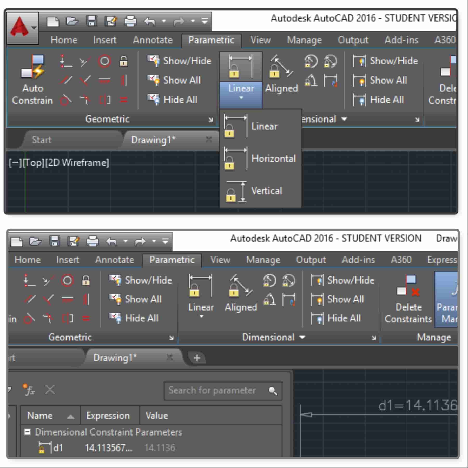
I opened new file in AutoCad software, draw rectangles, used trim, mirror and oter tools then used .
• "Parametic" command
• Chose "linear"
• Auto constain
• Parameters manager
• Created formula This means I can change one parameter and formula accordingly chnage all parametes. I used it to manipulate spaces among the rectangles.
I want to write about incorporate formulas and expressions, and how to manage them with the "Parameters Manager". Created and named user variables /box/. modified dimensional constraints and user variables either directly or with the "Parameters Manager". Double-click the dynamic constraint, "d1", and changed the "d1" to Length as the new name. Pressed "Enter or click" outside the edit box for accepting the change. On the Parametric tab- Manage panel- click "Parameters Manager". In the Name column, double-click "d2" and enter "Width". Pressed "Enter or click outside" the edit box for accepting the change How defined a user variable it is convenient to make a single change that affects multiple dynamic constraints. Double-click an empty row in the "Parameters Manager". Change the name of the new user variable from user1 to Tread. Press Enter or click outside the Parameters Manager palette to accept the new name. Change the value in the "Expression column" "Press Enter or click outside" the "Parameters Manager" to accept the new value. " In the Expression column" of d.., .. enter "Tread". These changes associated the value of each of these distances with the user variable, Tread. In the "Expression" column of the user variable, Tread, change the value The changes were updated automatically in the deck plan. How to create dimensional relationships between objects The Expression column in the Parameters Manager can contain constants, references to dynamic constraints, references to user variables, arithmetic operators, and functions. Consider the following example. Opened the drawing file. On the "Geometric panel", click show all and then hide all to confirm that geometric constraints have been applied. In the Parameters Manager, click the Length row. Clicked the Width row and observe the highlighted dynamic constraint. A full list of available functions is documented in the "AutoCAD User’s Guide Help" topic, "Constrain a Design with Formulas and Equations".
Step2
After learning about parametric design I started reading user manuals of Epilog mini laser cutting machine and vinylcutter. We should change our laser cutter tube as it had been broken. And the tech support came to change it was very interesting and informative process. I used Epilog mini 40W laser cutter and Roland vinyl cutter.
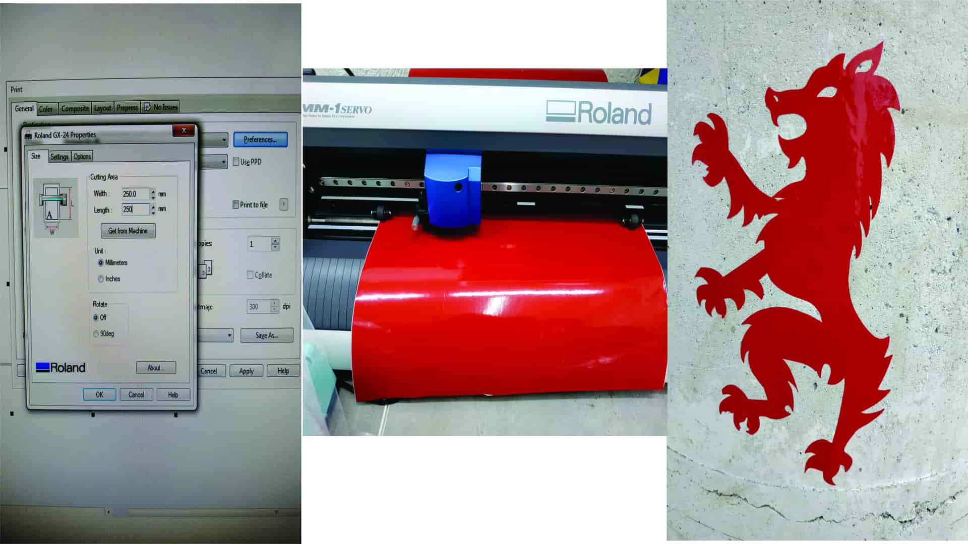
Step 3 Vinylcutting
We have a football club and it is need a logo and I decided to make a logo. Designed in Corel draw a lion and decided cut it by vinylcutter.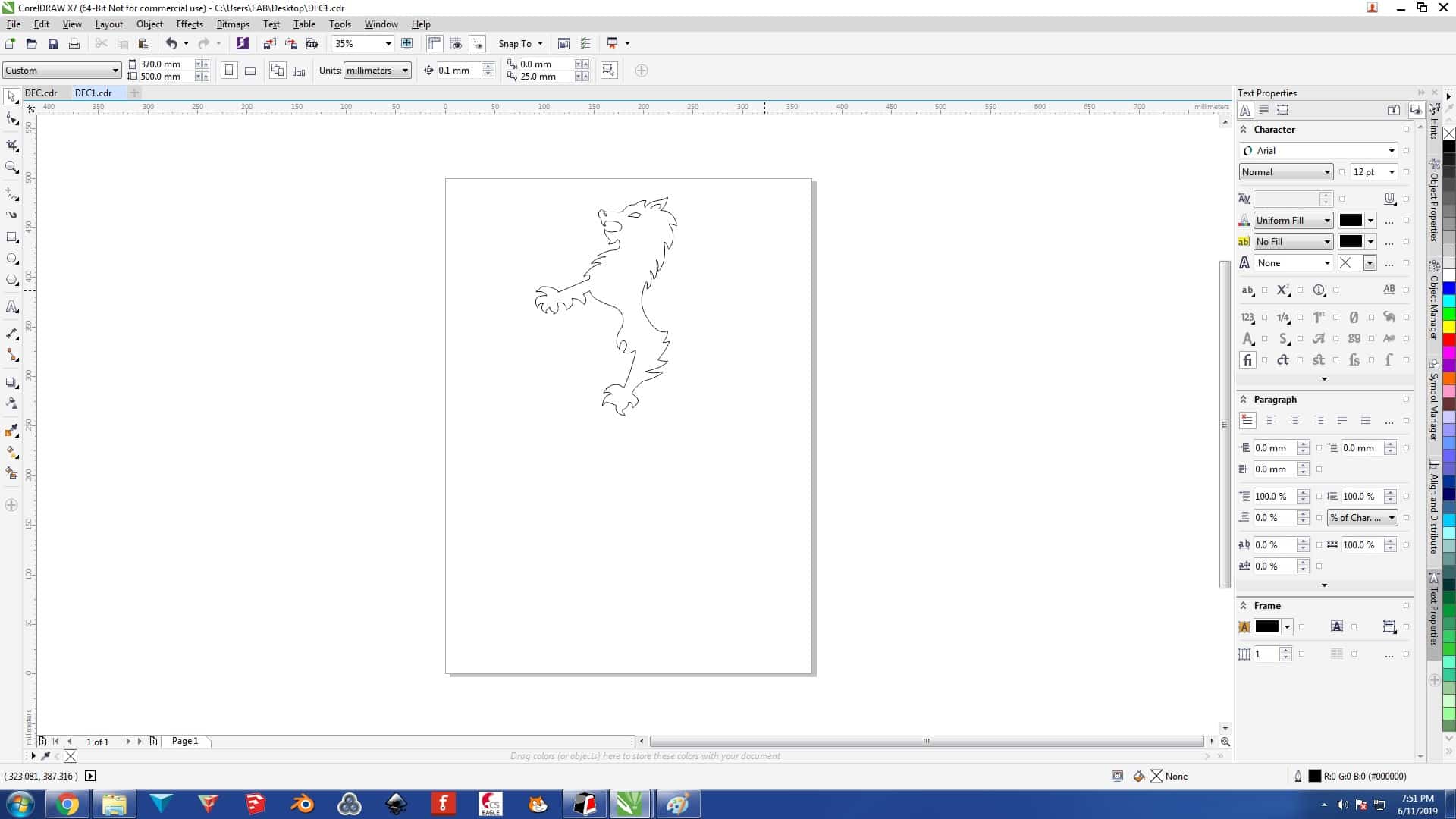
After finishing drawing process, I send the file to print and chose Roland GX20, then select the size I wanted to have, pushed apply -- ok and started cutting.
Step 4 cutting by laser cutter
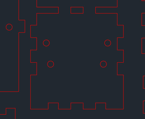
I decided to design a box for my final prject. I used AutoCad and Corel draw for this process.Design process
• opened AutoCad, created new file, draw rectangles• copied squeres different times for each part of my box
• then made spaces (10mm) between them Parametric part of this mentiond above.
Here you can see the design
 before I started the cutting I read user manual and identify list of actions I should do before starting
cutting process. We use Corel Draw as a software for the cutting machine, that's why I had to export my file.
There I met some problems, during the format changing process some parameters (sizes) had been changes.
I had to check all and changed the sizes manually.
before I started the cutting I read user manual and identify list of actions I should do before starting
cutting process. We use Corel Draw as a software for the cutting machine, that's why I had to export my file.
There I met some problems, during the format changing process some parameters (sizes) had been changes.
I had to check all and changed the sizes manually.
I did the following actions
• Switched on the laser cutter, compressor, and the filter
• Put plexiglass in the machine
• Opened Corel Draw software and the file. For cutting I had to change the color of outline, as the machiine understands RED color.
• After I clicked "print", chose laser cutting machine, "preferences" followed the user manual and gave the parameters to software of cutting machine " Vector cutting- for 6mm acrylic speed 8- power 100 - frequency 5000 " Unfortunatly there were an issue I found out, that I did not change the size of the paper in Corel draw. It was not match with the size of laser cutter's working table. After changing all that, I repeated the actions described above and sent the file to print. I cut my box parts.
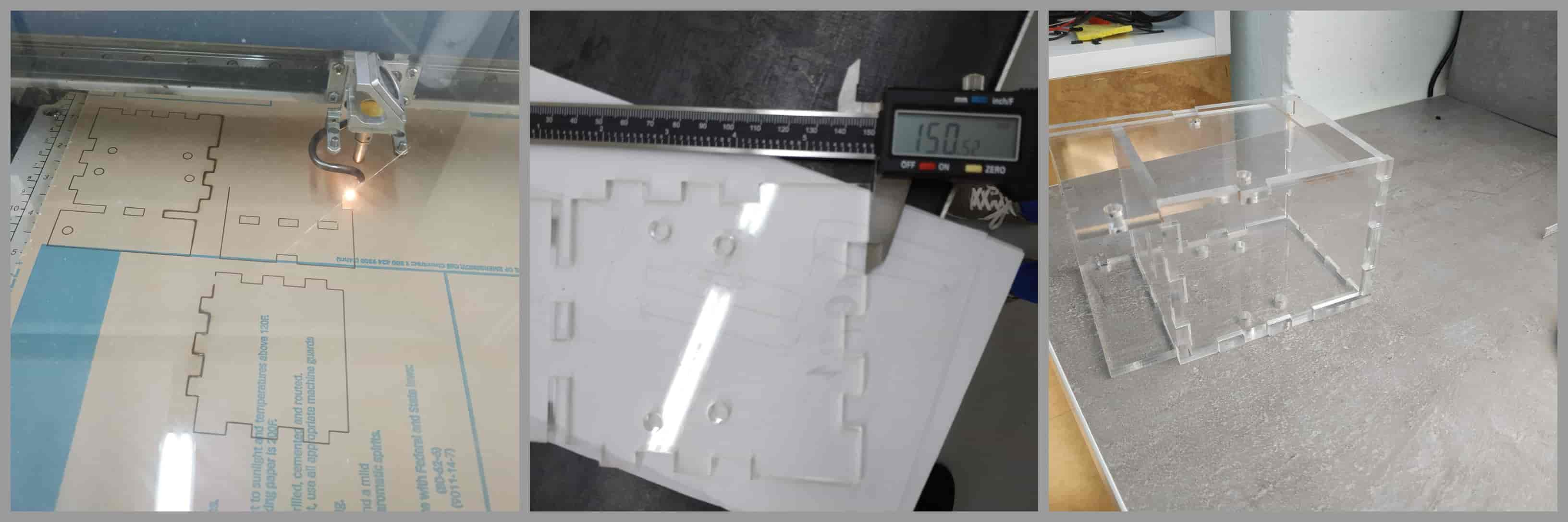
After cutting the box and making some measurments, I found out that I had to make one more box for electonics part of my final project. I decided to redrow it and finnaly use RhinoCeros 5 software, which I began learning before. As the walles and the furniture in the lab were yellow and white, I decided, that the second box would be yellow.
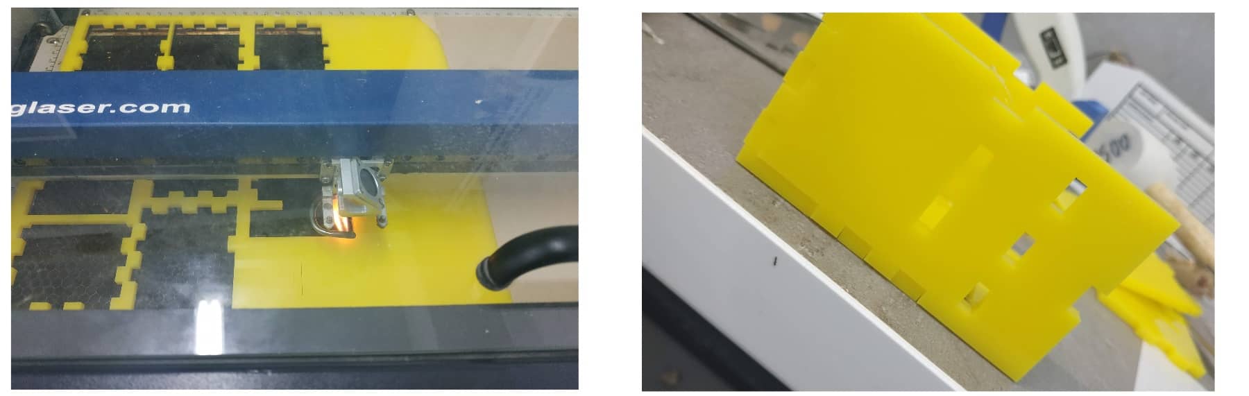
During the cutting process the coated paper of the plexiglass burned, I recommend remove it before cutting. After cutting the boxes I checked the sizes and started construct them, but for getting final result I still needed 3D printed parts of my boxes. During future weeks I will make the missing parts.
About laser cutter
• Engraving area - 610 x 305 mm• Maximum material thickness - 140mm
• Laser source - state-of-the-art, digitally controlled, air-cooled CO2 laser tubes are fully modular, permanently aligned and field replaceable.
• Air assist - attach an air compressor to our included Air Assist to remove heat and combustible gases from the cutting surface by directing a constant stream of compressed air across the cutting surface.
• Resolution - user controlled from 75 to 1200 DPI.
• Speed and power control - computer or manually control speed and power in 1% increments to 100%. Vector color mapping links speed, power and focus to any RGB color.
Conclusion
The parametric design is very useful and I will use it in future. I found out that I can use parametric design function in Fusion 365 and Rhinoceros, but for Rhino I need grasshopper plugin. I learned more professionally use vinylcutter and laser cutter machines.Parametric drawing has many applications for disciplines that require applying and maintaining design specifications. Geometric and dimensional constraints work together to include the design intent and requirements within a drawing. In the following lessons, you learn how to apply and work with constraint
Files
• Box v1• All parts
• Lion